1
MZ-IR12
SHARP
SERVICE MANUAL
COD E : 0 0 Z M Z 1 R 1 2 / / -E
S-RAM Board
MODEL
MZ-1R12
(For MZ-700)
~-----------------------CONTENTS------------------------~
1. OUTLINE "'"''''''''''''''''''''''''''''''''''''''''''''''''''''''''''''''''''''''''''''''''"""""""""""""""""""""'''''''''''''' 1
2. FUNCTIONS """''''''''''''''''''''''''''''''''''''''''''''''''''''''''''''''''''''''''''''''''''''............ " ....... """ ..... " .. """,,. 1
3. CONNECTION METHOO ..... " .. """ .... """ ..... " ..... ""." .. " .. ",, ............................ ,, ... "'''''''''''''''''''''''''' 1
4. SPECIFICATIONS '''''''''''''''''''''''''''''''''''''''''''''''''''''''''''''''''''''''''''''''''''''''''''''"'''''''''''''''''''''''''''''''' 1
5. BLOCK DIAGRAM ................................................. " ......................... " ............ '''''''''''''''''''''''''''''''''''' 1
6. DIP SWITCH SETIING '"''''''''''''''''''''''''''''''''''''''''''''''''''''''''''''''''''''''''''''''''''''''''""""'''''''''''''''''''' 1
7. TROUBLESHOOTING " ....... " ....... " ......................... " .............. "" ................ " ......................................... 2
8.
9.
10.
11.
CONNECTOR SIGNAL TABLE """"''''''''''''''''''''''''''''''''''''''''''''''''''''''''''''''''''''''''''''''''''......... " ......... 2
PART LOCATIONS DIAGRAM ''''''''''''''''''''''''''''''''''''''''''''''''''''''''''''''''''''''''''''''''''''''""""""'''''''''''' 3
CIRCUIT DIAGRAM """""""'"''''''''''''''''''''''''''''''''''''''''''''''''''''''''''''''''''''''''''''""""'''''''''''''''''''''' 4
PARTS LIST AND GUIDE ................................................ " ................ " ................ " ................ " " ............ 7
SHARP CORPORATION
MZ-IR12
1. OUTLINE
6. DIP SWITCH SETIING
The MZ-1R12 (S-RAM board) can be used with the MZ-700
Eight-bit port addresses are output from the ZSO·CPU.
either for a boot loader function or as an external memory.
Because three consecutive port addresses are used with
this card, the six high-order bits of the eight-bit address
signal are selected by the switch in order to set the port
address.
The MZ-1U03 is needed to connect this card to the MZ-700.
.
--- -- ---
Z.FUNCTI6NS
-
.
Meaning
Factory setting
1
A2
OFF
2
A3
ON
Used for setting the port
address.
3
A4
ON
Used for setting the port
address.
4
AS
ON
Used for setting the port
address.
5
A6
ON
Used for setting the port
address.
6
A7
ON
Used for setting the port
address.
7
MSEL
ON
(1) With the M7-700...capahilit)l-f.o,,-b00tiFf§-slmlfltaneotfS
with the supply of power.
(2) Composed of CM OS-RAMs with backup battery func tion for capability for use as a static memory.
(3) Built-in address counter provides automatic add res s
incrementation for each reading or writing operation ,
thus simplifying reading and writing of continuou s
data:····
3. CONNECTION METHOD
I us~a
or setting the port
address.
Selection of the
P·ROM.
After confirming that the power supplies of the main un it
and the extension unit (MZ·1U03) are OFF, insert this card
into the slot of the extension unit. To turn on the pawe r,
8
first turn on .the power of the extension unit and then turn
4. SPECIFICATIONS
(3) Charging time
(4) Power supply
(E) Elements used
An
P·ROM internal address
ON
setting.
The relationship between the switch position and the logic
level is shown below. The port addresses of this card are
where the logic levels of the address and of the switch are
the same.
on the power supply the MZ·700.
(1) Memory capacity
(2) Data hold time
Remarks
Segment
Switch position
32K bytes
approx. 44 days
(approx. 1.E months)
100% charge in 29 hours
E VDC ± 10%
CM OS static RAMs
(2K bytes x 16)
Logic level
ON
1
OFF
0
Note that the port addresses set at the factory are F8,
F9, and FAH.
The following is the meaning of the addresses selected by
address bits AO and Al.
A1
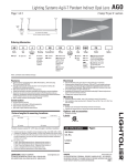
5. BLOCK DIAGRAM
AO A7
10RQ
AO
OUT command
IN command
0
0
Address high-order
setting
0
1
Address low-order
setting
Data reading
1
0
Data writing
Not in use
1
1
Not in use
Not in use
Address counter reset
AD
MSEL and A 11 setting
This S·RAM board has a PROM (for booting the MZ-700)
allocated to addresses $ESOOH - EFFFH. Although this
PROM has a memory capacity of 4K bytes, there is only
00-07
2K_hytes of allocated memory space-..-For-this· reason, the
All bit of the PROM address line is switched ON·OFF to
switch the address and make effective use of the PROM.
AO-A15
f-:..---/
Note The address counter is incremented automati-
Signal
Segment
Meaning when ON
Meaning when OFF
MSEL
7
ROM allocated.
ROM cut off.
All
8
cally with the input/output of data.
-2-
PROM $0000 - $07FF $0800 - $OFFFF ROM
ROM is selected.
is selected.
8, CONNECTOR SIGNAL TABLE
7, TROUBLESHOOTING
Interface Signals
START
Number
of
signals
Polarity
1
N
I
*IORDS
1
N
I
liD request Signal
*RDB
1
N
I
Read command
*WRB
1
N
I
Write command
Signal name
Input
or
Function
output
Check CMOS S-RAM terminal voltage
*MREQ8
.NG
--
--
Check battery voltage.
Memory request signal
--
Check S-RAM reading/writing.
(Usa R!W check program.)
NG
ADS - A158
8
P
I
Memory or 1/0 address
select signal
DOB - D7B
16
P
I/O
Data 110 address select
signal
ChEick address decoder circuit.
Check S-RAM.
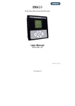
Interface pin locations
Check address counter drcuit.
A (parts side)
B (solder side)
1
+5 V
+5 V
2
02B
D3B
No.
RfW check program for the MZ-700
'0
20
30
40
50
60
70
80
90
INPi$F8,A:A=85
FOR 1=0 TO 32767
DU1#$FA,A:NEXT I
PRINT"READ":INp#SF8,A
FOR 1=0 TO 32767
INP~$F9,A:IF A=65 THEN 80
GOTD 90
NEXT I :PRINT"CHECI< ... 01<" :END
PRINT"ERROR ... ADDRESS=" ;HEX$ [!
) ;
"H"
3
D1B
D4B
4
DaB
D5B
5
GND
D6B
6
A15B
D7B
7
A14B
8
A13B
S
A12B
"WRB
10
A,1B
*RDB
11
Al0S
*IORDB
12
AS8
*MREQ8
13
A8B
GND
14
A7B
15
AS8
16
A58
17
A4B
18
A38
19
A2B
20
A1B
21
AaB
22
GND
GND
(parts sidel
22 ............ .. 3.2, 1 parts side (AI
22
-3-
3.2,1 parts side (SI
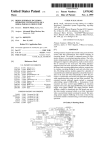
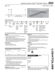
9. PART LOCATIONS DIAGRAM
LSHARP
MZ-IRIZ;'I!
-4-
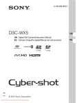
MZ-IR12
10. CIRCUIT DIAGRAM
*RDa~
-
*WRB
LSU
LeNI-lIS
r-r--r-r---,rT",,-om
o
A7B~
AGB
,
'"
''''''
I
LS1BS
2
IUY--
"12
I eNI_Ala
May!--
---='r,~,--;~,~'~,~'~=======::=~ PAO
~12C
,,'
f
<IilRAI
(2-02)
(2-A2)
~ 2G1SI652¥O~'"-=~======:=~jWAO
2Yl~:~
(2-02)
<!il IVl
"
LCNI-Al1
2
------t
I eNI-AIS
UORQB
I eNI-llll
"
1(; Mill
~A
ASB LeNt-AIS
A2B
r-~--oZDl (J-EH)( 2-02) (I-C4)
-,OL:::.-'
H.rSELo-_ _
",00
rcN"JAi61
Atll
(1-05)
B
POW~''-'A",c(-:;;;:-+-OABO-ABIO(a-AI)
1 OA
o~ 2
DB W~ OB
10 DC ,.s OC"
9 DD 19~OD 1
11
DOB
+WAI (2-02)
.. WA2 (2-A2)(8-Cl)
:NZ
15 UP
eNI-A(
0111
CNl-A~
0211
CNI-AZ
A
OHI
eNI-lIS
DS8
CN]-B4
16 B
17 1I
DGB
CN1_B~
D7B
eNI-lI6
~
Ml
,
+5V
AB2
ADS
LOAD
,"",<;Am
eNI-Bl
:: 1\
nSIl
ZO I
""
13:
ABJ
I' CLR
"
I
A "
A ~
A I
:a 11
A 2
MU
401fl88r
(Z-A6 )
AGS
eNl AZI
AlB
I CN1-A20
"'* *
"" rIr 22tlPFX2
(I_B6)
*WAI o,~,..-------'
(1-116)
*WAO o,~,..-------;
VI
VB
'"
'" '"
ABIO
f-f----~'~"
,co
UdREQB
I CNt-BIZ
,
lot
2
~::======~"~~~--1-t-1-!
13
eNI-AS
r-"\.
AISII
I CNI-AB
I eN!
"
"
"' " "
..
:f"'"
1
'M
o
4.7Kn
LSI93
O~-'",--~.--<0 *ld5EI..( 2-112){ 3-C I )
'
1..514
AIO
C8
b~ 220rF)(~
b
cs
(2-A5)
Z01
1
(2-117 ) CSO-*C515
..
'"
'M
( 2-85 ) ABO-ABIC
1
"
*cs
~
'
1
~ *C58
>J·C52
11'CSI
*C50
-
~
L
*C54
f-
~ *C56
*C55
-
I-
1
~ ",C57
+5V~
CNI-BI
",csa
-
I-
CNI-AS
CNI_BI8
'"
'M
'M
~
( 2-8 4) OBO-OB7
".
."
'"
'CO
'"
'"
'"
1-1'15)
"
:~
CNI-AI?
CNI-Ala
CI;]-AI5
CNI-AI4
CNI-AIS
CNI-AI2
CNI-AIl
-
MC'
MC.
-
6116
6115
r---
-
-
MO'
C-
611 G
,0
'"
6116
I--
MO'
-
6116
I-
'"
6116
II-
g~
*WE
-
*, r
J
-
-
1
L
J;
T
l-
C-
(
L,,"C514
fl"C515
T
;r, T
I I
~CS 18
L
1
J;
T
-
I-
*CSI2
tC511
01
I
I
1==
I
I-
f I
2SA6"l8C
r---r------,-----r---QC-IdOS
M"
6lU
15 04
to
~
-
'"
6115
PS
17 01
*OE
100n)(8
-r----- ~l
?~~,
r---
-
11 D2
~
r-----
MO'
6116
I~ g~
CN1-A21
CNI-AI8
CNI_B22
~~
-05) 't<),lSEI..
CNI-Ale
CNI-A22
AS
23
22 A9
19 A10
*\\,A~
CNI-A20
40HI88r
' -_ _ _ _0-0 *C5E( 4-06)
L l - - -_ _+-_K>OBO-H 8-111)
AI2B~
AIIB
51
1d20
j-''-----<f'4 lsiO
11 I
AUB J eNI-A7
MC'
(2-A5)
ZOI
(1-1I6)*RAOq
"
LS14
AI5B
14*CSg
13*C51
R1l
IS2[176 SIKn
".
R1
470n
51Kn
r-,-jK ~k121
,
'"
51Kn
."
], T
1"CS1O
J_;.css
{2-AS)CEI
.OE
-
AO
,"
-
I-
I-
I-
-
I--
"
; AS
,M
M
OM
'"
' A'
22 A9
M21
I' Ale 2782
r---
MO'
'"
Il-
6116
o.
'
01 10
GI16
ft--
-
'"
6116
'"
6116
MO'
II-
II-
GIIG
'"
6116
-
'"
6116
."
"' "
"'
"" ""
"' "
*C~1
r
-5-
-
=-
I-
~
;r,
r
I--
I--
f-
;r,
L
*
T
-
C--
;r, T
;r,
I
-
M.l1 .1d12. 14
MI5-!d20
1>IZl-!dSI
~
1==
! 1 3 J
-6-
PARTS LIST
NEW
PART
MARK
PRICE
RANK
PART CODE
No.
PART
RANK
PART
NAME
-
1
V H i H Ma 1 1 6 L P 3 N
AZ
B
STATIC RAM
2
vHi
SN74LSOO-l
AE
B
IC
3
vHi
SN74LS14-1
AM
B
IC
IM71
4
SN74LS30-1
AE
B
IC
IM21
S
v Hi
vHi
SN74LS155N
AP
B
IC
6
vHi
SN74LS193N
AR
B
IC
7
V H i SN74LS245N
AR
B
IC
IM11
B
vHi
SN74LS136N
AE
B
IC
IM3,M81
9
vHi
TC40HOOOPl
AF
B
IC
IM141
10
vHi
TC40H138Pl
AN
B
IC
IM11,M121
-c /
[M22-M31,M15-M20J
IM61
IM131
IM4,S,~
11
V S 2 SA 6 7 3
AC
B
Transistor
12
VS 2
-c -1
AD
B
Transistor
IQ11
13
VHD1S2076A/-l
AB
B
Diode
IDlI
14
V R 0 -5 T 2 E Y 1 0 1 J
AA
C
Resistor (114W 100)
IR10,1B-2SI
1S
V R 0 -5 T 2 E Y 3 9 1 J
AA
C
Resistor (1/4W 390)
IR81
16
V A 0 -5 T 2 E Y 4 7 1
J
AA
B
Resistor (1/4W 470)
IR7,R121
17
V R 0 -5 T 2 E Y 2 0 2 J
AA
e
Resistor (1/4W 2K)
IR91
18
V R 0 -5 T 2 E Y' 0 2 J
AA
e
Resistor (1/4W 1K)
IR1 ,3,14, 1S,4,21
se'
2 1 3
1A
IQ21
19
V R 0 -5 T 2 E Y 5 1 2 J
AA
e
Resistor (1/4W 5.1 K)
20
V R D -5 T 2 E Y 5 1 3 J
AA
e
Resistor (1/4W 51 K)
21
V R 0 -5 T 2 E Y 4 7 4 J
AA
e
Resistor (1/4W 470K)
IR171
22
RMPTC847 2 QCKB
AD
e
Block resistor (4.7 kO x 8)
INR11
IR16,R111
IRS,61
23
VCKYPUl HB221 K
AB
e
Capacitor (50V, 200p)
24
VCKYPUl HB, 02K
AA
C
Capacitor (SOV, 1000p)
VCKYPU1 HF1 04Z
AB
C
Capacitor (25V, 0.1ft)
[C1 0,14, 16-18,20-221
VCKYPU1 HF1 04Z
AB
C
Capacitor (25V, 0.1ft)
[C1 ,2,6,7,9,13,191
26
VCEAAU1CW227Q
AC
C
Capacitor (16V, 220ft)
IC31
27
OAE322649/1/1
BC
B
Dip switch
28
OAE3283841111
8C
N
8
Battery (NI-CD)
29
OAE1R12CTN/II
AZ
N
D
Carton
30
OAE1R120/MIII
BF
N
D
Instruction Manual
2S
,
N
-7-
IC4,11,12,8,SI
le1S1
~~~MZ-IRl~~~~~~~~~-
SHARP
SHARP CORPORATION
Industrial Instrument Group
Reliability & Quality Control Cent.
Yamatokoriyama, Nara 639-11, J,
October 1984
Printed in Japa,