1
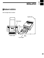
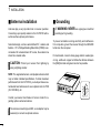
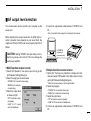
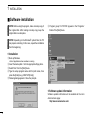
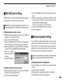
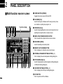
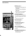
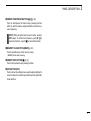
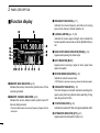
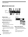
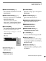
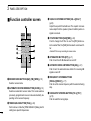
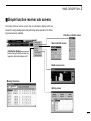
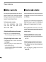
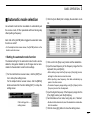
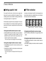
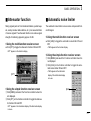
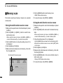
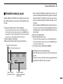
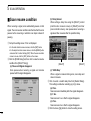
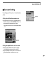
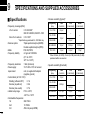
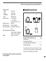
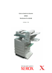
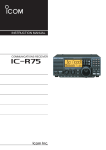
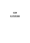
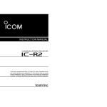
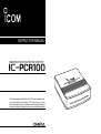
INSTRUCTION MANUAL
COMMUNICATIONS RECEIVER FOR COMPUTER
iPCR100
This device complies with Part 15 of the FCC rules. Operation is subject to the following two conditions: (1) This device may not cause
harmful interference, and (2) this device must accept any interference
received, including interference that may cause undesired operation.
IMPORTANT
OPERATING THEORY
READ ALL INSTRUCTIONS carefully and com-
Electromagnetic radiation which has frequencies of 20,000
Hz (20 kHz*) and above is called radio frequency (RF) energy
because it is useful in radio transmissions. The IC-PCR100
receives RF energy from 0.5 MHz* to 1300 MHz and converts
it into audio frequency (AF) energy which in turn actuates a
loudspeaker to create sound waves. AF energy is in the range
of 20 to 20,000 Hz.
pletely before using the receiver.
SAVE THIS INSTRUCTION MANUAL — This
instruction manual contains important operating instructions
for the IC-PCR100 COMMUNICATIONS RECEIVER FOR
COMPUTER.
USE antenna(s), such as a well-matched 50 Ω antenna and
feedline. For radio communications, the antenna is of critical
importance, along with sensitivity.
SYSTEM REQUIREMENTS
• IBM PC/AT compatible computer
• An RS-232C serial port (38400 bps or faster)
• Microsoft® Windows® 95 or Microsoft® Windows® 98
• Intel i486DX4 processor or faster (Pentium® 100 MHz or
faster recommended)
• At least 16 MB RAM
• At least 10 MB of hard disk space
• At least 640 × 480 pixel display (800 × 600 pixel display recommended)
i
* kHz is an abbreviation of kilohertz or 1000 hertz, MHz is abbreviation of megahertz or 1,000,000 hertz, where hertz is a unit of frequency.
OPERATING NOTES
The IC-PCR100 may receive its own oscillated frequency, resulting in no reception or only noise reception, on some frequencies.
The IC-PCR100 may receive interference from extremely
strong signals on different frequencies or when using an external high-gain antenna.
Versions of the IC-PCR100 which display “CE” on the serial number seal, comply with the essential requirements of the
89/336/EEC directive for Electromagnetic Compatibility.
CAUTIONS
RWARNING! NEVER connect the receiver to an AC
outlet. This may pose a fire hazard or result in an electric
shock.
NEVER connect other than the specified AC adapter to the
receiver. This connection will ruin the receiver.
NEVER connect the receiver to a power source of more
than 16 V DC such as a 24 V battery. This connection will ruin
the receiver.
NEVER expose the receiver to rain, snow or any liquids.
DO NOT use or place the receiver in areas with temperatures below 0°C (+32°F) or above +50°C (+122°F) or, in areas
subject to direct sunlight.
AVOID placing the receiver in excessively dusty environments.
AVOID the use of chemical agents such as benzine or alcohol when cleaning, as they damage the receiver surfaces.
Place unit in a secure place to avoid inadvertent use by children.
IBM is registered trademark of International Business Machines Corporation in
the U.S.A. and other countries. Microsoft® and Windows® are registered trademarks of Microsoft Corporation in the U.S.A and other countries. Screen shots
produced with permission from Microsoft Corporation. All other products or
brands are registered trademarks or trademarks of their respective holders.
For U.S.A. only (FCC information)
CAUTION: Changes or modifications not expressly approved by Icom Inc. could void the user’s authority to operate
this receiver.
Class B digital device users
This equipment has been tested and found to comply with the limits
for Class B digital devices, pursuant to Part 15 of the FCC Rules.
These limits are designed to provide reasonable protection against
harmful interference in a residential installation. This equipment generates, uses and can radiate radio frequency energy and, if not installed and used in accordance with the instruction manual, may
cause harmful interference to radio communications. However, there
is no guarantee that interference will not occur in a particular installation. If this equipment does cause harmful interference to radio or
television reception, which can be determined by turning the equipment off and on, the user is encouraged to try to correct the interference by one or more of the following measures:
- Reorient or relocate the receiving antenna.
- Increase the separation between the equipment and receiver.
- Connect the equipment into an outlet on a circuit different from that
to which the receiver is connected.
- Consult the dealer or an experienced radio/TV technician for help.
For Canada only
Operation is subject to the following two conditions: (1) this device
may not cause interference, and (2) this device must accept any interference, including interference that may cause undesired operation of the device.
ii
TABLE OF CONTENTS
IMPORTANT ...................................... i
SYSTEM REQUIREMENTS .............. i
OPERATING THEORY ....................... i
OPERATING NOTES ......................... i
CAUTIONS ........................................ ii
TABLE OF CONTENTS .................... iii
1 INSTALLATION ...................... 1 – 5
■ Hardware installation ................ 1
■ Antenna installation .................. 2
■ Grounding ................................. 2
■ AF output level selection ........... 3
■ Software installation ................. 4
■ RS-232C port setting ................ 5
■ Mouse property setting ............. 5
2 PANEL DESCRIPTION ........ 6 – 15
■ Multi-function receiver screen ... 6
■ Function display ...................... 10
■ Simple function receiver
screen ..................................... 12
■ Function controller screen ...... 14
■ Simple function receiver sub
screens ................................... 15
iii
3 BASIC OPERATION ........... 16 – 21
■ Receiving ................................ 16
■ Setting a frequency ................. 17
■ Setting a tuning step ............... 18
■ Receive mode selection ......... 18
■ Automatic mode selection ...... 19
■ Setting squelch level ............... 20
■ IF filter selection ..................... 20
■ Attenuator function ................. 21
■ Automatic noise limiter ........... 21
4 MEMORY CHANNELS ....... 22 – 25
■ General ................................... 22
■ Saving memory channels ........ 22
■ Selecting a memory channel ... 23
■ Memory channel
programming .......................... 24
■ Clearing a memory channel .... 24
■ Editing the memory list ........... 25
5 SCAN OPERATION ............ 26 – 33
■ Scan types .............................. 26
■ Programmed scan .................. 27
■ Setting scan edges ................. 28
■ Auto memory write scan ......... 29
■ Memory scan .......................... 30
■ Versatile memory scan ........... 31
■ Scan resume condition ........... 32
■ Scan speed setting .................. 33
6 BAND SCOPE .................... 34 – 35
■ Operation ................................ 34
■ Changing the automatic
sweep step limit ...................... 35
7 TONE SQUELCH OPERATION ... 36
8 TROUBLESHOOTING .............. 37
9 SPECIFICATIONS AND SUPPLIED
ACCESSORIES .................... 38 – 39
■ Specifications ......................... 38
■ Supplied accessories .............. 39
INSTALLATION
1
■ Hardware installation
Refer to the diagram below for connections.
Supplied antenna
External speaker
to an
RS-232C port
Personal computer
Ground
to an AC adapter
1
1
INSTALLATION
■ Antenna installation
Antennas play a very important role in receiver operation.
Connecting a poor quality antenna to the IC-PCR100 will result in less than optimum performance.
Select antenna(s), such as a well-matched 50 Ω antenna and
feedline. 1.5:1 of Voltage Standing Wave Ratio (VSWR) is recommended for a desired band. Of course, the antenna line
should be a coaxial cable.
CAUTION:
Protect your receiver from lightning by
using a lightning arrestor.
NOTE: The supplied antenna is a simple plain antenna which
may not obtain indicated specifications. To obtain maximum
performance from the IC-PCR100, you must purchase an external wide band antenna such as an optional Icom AH-7000
(25–1300 MHz), etc.
Contact your nearest Icom Dealer or Service Center for regarding optimum antenna locations.
The antenna connector type is BNC, so an adapter may be
necessary to connect an optional antenna.
2
■ Grounding
R WARNING: NEVER use a gas pipe or electrical
conduit pipe for grounding.
To prevent accidents involving electricity and interference
from computers, ground the receiver through the GROUND
terminal on the rear panel.
For best results, connect a heavy gauge cable to a water pipe
or long, earth-sunk copper rod. Make the distance between
the [GND] terminal and ground as short as possible.
INSTALLATION
1
■ AF output level selection
The received audio can be input into your computer via the
sound card.
r Connect an appropriate cable between IC-PCR100 and
PC.
• Use a 3-conductor stereo plug for connecting to the receiver.
Before inputting the received audio into the [LINE IN] connector (connector name depends on your sound card), the
output level of the [EXT-SP] must be set properly. Perform as
follows:
to [LINE IN]
CAUTION: Setting ‘STEREO’ and connecting a 2-con-
(depends on
your sound card)
ductor plug cause a short-circuit. This may damage the
audio power amplifier.
D Multi-function receiver screen
q Select ‘EXT-Speaker’ in the option menu to bring up the
[EXT-Speaker Setting] dialog box.
w Select the plug type as shown below.
• “STEREO” for 3-conductor stereo plug.
• “MONO” for 2-conductor
monaural plug.
e Select the output level
as shown at right.
• “SP” for internal or external speaker.
• “LINE” for PC sound
card or headphones.
[EXT-SP]
D Simple function receiver screen
q Right-click* the frequency indication to display shortcut
menu and select ‘EXT-Speaker’ in the Option menu to bring
up the [EXT-Speaker Setting] dialog box.
* When the mouse property is set for right-handed.
w Select the plug type.
• “STEREO” for 3-conductor stereo plug.
• “MONO” for 2-conductor monaural plug.
e Select the output level.
• “SP” for internal or external speaker.
• “LINE” for PC sound card or headphones.
r Connect an appropriate cable between IC-PCR100 and
PC.
3
1
INSTALLATION
■ Software installation
NOTE: Before using the program, make a backup copy of
the original disk. After making a backup copy, keep the
original disk in a safe place.
y Program group ‘IC-PCR100’ appears in the ‘Programs’
folder of the [Start] menu.
NOTE: Depending on the Windows® system files, the PC
may require rebooting. In this case, repeat the installation
from the beginning.
D Installation
q Boot up Windows.
• Quit all applications when windows is running.
w Insert the backup disk 1 into the appropriate floppy drive.
e Select ‘Run’ from the [Start] menu.
r Type the setup program name with full path name, then
press the [Enter] key. (A:\SETUP [Enter])
t Following dialog appears. Follow the prompts.
D Software update information
Software update information will be available at the Icom
America home page:
http://www.icomamerica.com/
4
INSTALLATION
■ RS-232C port setting
‘COM Port Error’ or ‘Communication failed’ dialog box appears
when the RS-232C serial port is not set correctly.
NOTE: When launching the program for the first time, this
setting dialog appears for setting the RS-232C serial port.
1
e Click the [POWER] button to temporarily pause the program.
r Right-click* the frequency indication to display shortcut
menu and select ‘COM Port’ in the Option menu to bring
up the [COM Port Setting] dialog box.
* When the mouse property is set for right-handed.
t Click the desired COM port number to choose it.
y Click the [OK] button.
D Multi-function receiver screen
q Before launching the program, make sure the IC-PCR100
interface unit is connected correctly.
w Launch the IC-PCR100 software.
e Click the [POWER] button in the tool bar or select ‘Power
OFF’ in the File menu to temporarily pause the program.
r Click the [PORT] button or select ‘COM Port’ in the Option
menu to bring up the [COM Port Setting] dialog box.
t Click the desired
COM port number to
choose it.
y Click the [OK] button.
■ Mouse property setting
The IC-PCR100 uses left and right buttons to rotate a control
knob on the multi-function receiver screen or to call up the
shortcut menu from the simple function receiver screen. Depending on the mouse property setting of the control panel,
main and sub mouse button functions are alternated.
In this instruction manual, the operation is described with
setting for right-handed (Windows® default setting).
D Setting the button configuration
D Simple function receiver screen
q Before launching the program, make sure the IC-PCR100
interface unit is connected correctly.
w Launch the IC-PCR100 software.
q Select ‘Settings’ from the [Start] menu and click ‘Control
Panel.’
w Open the mouse control panel.
e Select the button configuration to right- or left-handed.
r Click [OK] to set and exit the control panel.
5
2
PANEL DESCRIPTION
■ Multi-function receiver screen
q POWER BUTTON [POWER]
Toggles the receiver power ON and OFF.
w FILE MENU [File]
Used for turning the software on/off, saving memory channel contents or quitting the program, etc.
q w erty u io !0
Function display
!1
e VIEW MENU [View]
Used for showing/hiding the memory list screen/tool bar or
selecting the simple function receiver screen.
r SIMPLE FUNCTION RECEIVER BUTTON
Push to selects the simple function receiver screen.
t BANK MENU [BANK]
Used for selecting the memory bank.
y MEMORY LIST SCREEN BUTTON
Push to display or to hide the memory list screen.
u EXTERNAL SPEAKER SETTING BUTTON (p. 3)
Push to display the external speaker setting dialog box.
i OPTION MENU [Option]
Used for displaying the external speaker setting dialog box
or COM port setting dialog box.
!2 !3 !4 !5
!6
!7
!8 !9 @0 @1
@2 @3
o COM PORT SETTING BUTTON (p. 5)
Push to display the COM port setting dialog box.
!0 EXIT BUTTON
Push to quit and exit this software.
6
PANEL DESCRIPTION
!1 CLOSE BUTTON
Push to quit and exit this software.
!2 ATTENUATOR BUTTON [ATT] (p. 21)
Push to turn the 20 dB attenuator on and off.
!3 VOLUME CONTROL [VOLUME] (p. 16)
Adjusts the audio output.
• Right-click* to increase the volume level; left-click* to decrease
the volume level.
!4 AUTOMATIC NOISE LIMITER BUTTON [ANL] (p. 21)
Push to turn the automatic noise limiter for receiving AM
signals on and off.
!5 SQUELCH CONTROL [SQUELCH] (p. 20)
Adjusts the squelch threshold level. The squelch removes
noise output from the speaker (closed condition) when no
signal is received.
• Right-click* to increase the squelch level; left-click* to decrease
the squelch level.
2
!8 SCAN SPEED CONTROL [SPEED] (p. 33)
Sets the speed at which scans search through frequencies/memories for signals.
• Right-click* to increase the speed; left-click* to decrease the
speed.
!9 SCAN DELAY TIME CONTROL [DELAY] (p. 32)
Sets the period in which a scan pauses after receiving a
signal.
• Right-click* to increase the period; left-click* to decrease the period.
@0 TUNING STEP UP/DOWN BUTTONS [TS J]/[TS K]
(p. 18)
Push to select the tuning steps.
@1 TUNING DIAL (p. 17)
Push to set the receive frequency with the selected tuning
step.
• Right-click* to increase the frequency; left-click* to decrease the
frequency.
!6 TONE SQUELCH BUTTON [T-SQL] (p. 36)
Push to show or hide the [TONE SQUELCH] dialog box for
setting tone squelch frequencies.
@2 MEMORY BANK UP/DOWN BUTTONS
[BANK ∧]/[BANK ∨] (p. 23)
Push to select the memory bank.
!7 RECEIVE MODE BUTTONS [FM], [WFM], [AM], [AUT-M]
(pgs. 18, 19)
Select a receive mode. The [AUT-M] button, automatic
mode, selects a previously programmed receive mode automatically depending on a receive frequency.
@3 MEMORY CHANNEL UP/DOWN BUTTONS
[CH ∧]/[CH ∨] (p. 23)
Push to select the memory channel.
* When the mouse property is set for right-handed.
7
2
PANEL DESCRIPTION
@4 KEYPAD [0]–[9], [•], [CE] (p. 17)
➥ [0] to [9] are used to input a receive frequency or memory channel directly.
➥ [•] (Decimal) button is used to set the MHz digit when inputting a frequency.
➥ [CE] (Clear) button is used to clear mistakes while inputting a receive frequency or memory channel.
@4
@5 IF FILTER BUTTONS [NAR]/[WID] (p. 20)
Push to change the IF filter in use. The [WID] button selects a wider filter, the [NAR] button selects a narrower filter.
• Usable IF filters vary according to receive mode.
@6 SCAN STOP BUTTON [STOP] (p. 26)
Push to cancel scan operation.
@7 PROGRAMMED SCAN BUTTON [PROG] (p. 27)
Push to start/stop programmed scan.
• “PROG” flashes while scanning.
@8 SPAN +/– BUTTONS [SPAN+]/[SPAN–] (p. 34)
Push to select one of four levels for the band scope frequency span.
@5
@6
@7 @8 @9 #0 #1 #2 #3
#4
#5 #6 #7
@9 AUTO MEMORY WRITE SCAN BUTTON [AUTO] (p. 29)
Push to start/stop auto memory write scan.
• “AUTO” flashes while scanning.
8
PANEL DESCRIPTION
2
s/❙ ❙] (p. 34)
#0 SWEEP START/PAUSE BUTTON [s
Push to start/pause the band scope (sweep) function
which is used to observe signal conditions around the receive frequency.
NOTE: While using the band scope function, audio is
NOT output. To monitor the frequency, push [s/❙ ❙] to
pause the function, or push [■] to cancel the function.
#1 MEMORY SCAN BUTTON [MEMO] (p. 30)
Push to start/stop any of the memory scans.
• “MEMO” flashes while scanning.
#2 SWEEP STOP BUTTON [■] (p. 34)
Push to stop a band scope (sweep) function.
#3 SET BUTTON [SET]
Push to show the setting screen used to adjust settings for
scan functions, the band scope function and the automatic
mode function.
9
2
PANEL DESCRIPTION
■ Function display
q
e FREQUENCY INDICATION (p. 17)
Indicates the receive frequency and data as it is being
input such as memory channel numbers, etc.
w
y
u
i
o
!0 !1 !2 !3
!4
!5
!6 !7
e
r S (SIGNAL) METER (pgs. 16, 20)
Indicates the receive signal strength. Also indicates the
S-meter squelch receive level set via the [SQUELCH] control.
r
t
t BAND SCOPE PAUSE INDICATOR [PAUSE] (p. 34)
Appears when pausing the band scope.
!4
y BUSY INDICATOR [BUSY]
Appears when receiving a signal or when signal noise
opens the squelch.
u RECEIVE MODE INDICATORS (p. 18)
Indicate the current receive mode.
q MEMORY BANK INDICATOR (p. 23)
Indicates the memory bank number (and its name if it has
one) being received.
w MEMORY CHANNEL INDICATOR (p. 23)
Indicates the memory channel number (and its name if it
has one) being received.
• The name darkens when the receive frequency changes from the
stored one.
10
• “WFM” lights in red when receiving a stereo broadcast program.
i TUNING STEP INDICATOR (p. 18)
This is the frequency increment used when selecting a frequency using the tuning dial and when searching for signals using a scan function.
o IF FILTER INDICATOR (p. 20)
Indicates the selected IF filter and signal passband width.
!0 ATTENUATOR INDICATOR [ATT] (p. 21)
Appears when the attenuator function is on.
PANEL DESCRIPTION
!1 AUTOMATIC NOISE LIMITER INDICATOR [ANL] (p. 21)
Appears when the automatic noise limiter is on.
!2 TONE SQUELCH INDICATOR [T-SQL] (p. 36)
Appears when the tone squelch is on.
!3 AUTOMATIC MODE INDICATOR [AUT-M] (p. 19)
Appears when the automatic mode function is on.
2
!8 LIMIT INDICATOR (p. 35)
➥ Indicates when the tuning step is greater than the automatic sweep step setting.
➥ In the diagram, the tuning step is greater than the automatic sweep step setting and the tuning step (TS) and
the sweep step width are not the same.
!4 MAXIMUM FREQUENCY SPAN INDICATORS (p. 34)
➥ Indicate the upper and lower observable frequency limits
around a receive frequency.
➥ In the diagram, the upper and lower limits are +100 kHz
and –100 kHz.
!5 FREQUENCY SPAN INDICATION (p. 34)
Indicates the frequency span selected with the [SPAN–] or
[SPAN+] button.
!6 CENTER FREQUENCY INDICATOR (p. 34)
Indicates the center frequency of the frequency span; this
is for the currently received frequency.
!7 SWEEP STEP INDICATOR (p. 34)
Indicates band scope sweep step.
11
2
PANEL DESCRIPTION
■ Simple function receiver screen
qwer
t
y
u
i
o !0 !1
Simple function
receiver
Information display
!2 !3 !4 !5
!6
q POWER BUTTON [PWR]
Toggles the receiver power ON and OFF.
!7
!8
!9
• Shortcut menu
w AUTOMATIC MODE INDICATOR [AUT-M] (p. 19)
Appears when the automatic mode function is on.
e RECEIVE MODE INDICATOR (p. 18)
Indicates the current receive mode.
• “WFM” lights in red when receiving a stereo broadcast program.
r S (SIGNAL) METER (pgs. 16, 20)
Indicates the receive signal strength. Also indicates the
S-meter squelch receive level set via the [SQL J]/[SQL K]
buttons.
t FREQUENCY INDICATION (p. 17)
Indicates the receive frequency.
• Double-click to display/hide the information display.
• Right-click* to bring up the shortcut menu.
12
y MEMORY CHANNEL NAME INDICATOR
Indicates the memory channel name (if it has one).
• The name darkens when the receive frequency changes from the
stored one.
• Double-click to display/hide the information display.
• Right-click* to bring up the shortcut menu.
PANEL DESCRIPTION
2
u MEMORY BANK BUTTON [BANK] (p. 23)
Click to indicate the memory bank menu to select the
memory bank number.
!2 BUSY INDICATOR [BUSY]
Appears when receiving a signal or when signal noise
opens the squelch.
i MEMORY CHANNEL BUTTONS [1] – [5] (p. 23)
Select memory channels between 1 to 5 and indicate the
selected memory channel number.
!3 ATTENUATOR INDICATOR [ATT] (p. 21)
Appears when the attenuator function is on.
• The selected memory channel number lights red.
• Memory channels 6 – 50 cannot be selected with these buttons.
Use the memory list screen to select these memory channels.
o MENU BUTTON [MENU]
Click to indicate the simple receiver menu to display/hide
the sub menu screen such as memory list screen.
• The information display automatically appears when the function
controller screen is selected.
• Menu screen
!4 AUTOMATIC NOISE LIMITER INDICATOR [ANL] (p. 21)
Appears when the automatic noise limiter is on.
!5 MEMORY BANK INDICATOR (p. 23)
Indicates the memory bank number.
!6 MEMORY BANK NAME INDICATOR (p. 23)
Indicates the memory bank name (if it has one).
!7 IF FILTER INDICATOR (p. 20)
Indicates the selected IF filter and signal passband width.
!8 TUNING STEP INDICATOR (p. 18)
Indicates the frequency increment used when selecting a
frequency using the tuning dial and when searching for signals using a scan function.
!0 VOLUME BUTTONS [J]/[K] (p. 16)
Adjust the audio output.
!9 TONE SQUELCH INDICATOR (p. 36)
Indicates the selected tone squelch frequency when the
tone squelch is on.
!1 VOLUME INDICATOR (p. 16)
Indicates the audio output level.
* When the mouse property is set for right-handed.
13
2
PANEL DESCRIPTION
■ Function controller screen
q
t
y
u
w
i
r
e
o
q RECEIVE MODE BUTTONS [AM], [FM], [WFM] (p. 18)
Select a receive mode.
w AUTOMATIC RECEIVE MODE BUTTON [AUT-M] (p. 19)
Selects an automatic receive mode. This mode selects a
previously programmed receive mode automatically depending on the receive frequency.
e TONE SQUELCH BUTTON [TSQL] (p. 36)
Push to show or hide the [TONE SQUELCH] dialog box for
setting tone squelch frequencies.
14
r SQUELCH UP/DOWN BUTTONS [SQL J]/[SQL K]
(p. 20)
Adjust the squelch threshold level. The squelch removes
noise output from the speaker (closed condition) when no
signal is received.
t IF FILTER BUTTONS [NAR]/[WID] (p. 20)
Push to change the IF filter in use. The [WID] button selects a wider filter, the [NAR] button selects a narrower filter.
• Usable IF filters vary according to receive mode.
y ATTENUATOR BUTTON [ATT] (p. 21)
Push to turn the 20 dB attenuator on and off.
u AUTOMATIC NOISE LIMITER BUTTON [ANL] (p. 21)
Push to turn the automatic noise limiter for receiving AM
signals on and off.
i FREQUENCY UP/DOWN BUTTONS
[FREQ J]/[FREQ K] (p. 17)
Push to set the receive frequency with the selected tuning
step.
o TUNING STEP UP/DOWN BUTTONS [TS J]/[TS K]
(p. 18)
Push to select the tuning steps.
PANEL DESCRIPTION
2
■ Simple function receiver sub screens
The simple function receiver screen has an information display and 5 sub
screens for saving desktop space and performing various operation. The following sub screens are available.
•Function controller screen
•Scan controller screen
•Information display
Double clicking the simple receiver also
toggles the information display on/off.
•Band scoop screen
•Memory list screen
•Setting screen
15
3
BASIC OPERATION
■ Receiving
• Pushing the PC’s [c] or [d] key also sets the audio level.
Make sure the hardware installation is finished. (p. 1)
D Using the multi-function receiver screen
q Click [POWER] to turn power ON.
w Click the [VOLUME] control with the sub mouse button to
increase the audio level; click the [VOLUME] control with
the main mouse button to decrease the audio level.
• When clicking and holding the control, the audio level scrolls up
or down.
q Power switch
e Select mode
e Set an operating frequency and mode. (pgs. 17, 18)
r Click the [SQUELCH] control with the sub mouse button to
increase the squelch level (tight squelch); click the
[SQUELCH] control with the main mouse button to decrease the squelch level (loose squelch).
• When clicking and holding the control, the squelch level scrolls
up or down.
t When a signal is received:
➥ Squelch opens and audio is emitted from the speaker.
➥ The S-meter shows the relative signal strength.
D Using the simple function receiver screen
q Click [PWR] to turn power ON.
w Click [MENU] and select the ‘Function Controller’ when it
is not displayed.
e Click [VOL J] or [VOL K] to set the desired audio level.
• When clicking and holding either button, the volume level scrolls
up or down.
• Pushing the PC’s [c] or [d] key also sets the audio level.
r Set an operating frequency and mode. (pgs. 17, 18)
t Click [SQL J] or [SQL K] to set the desired squelch level.
• When clicking and holding either button, the squelch level scrolls
up or down.
y When a signal is received:
➥ Squelch opens and audio is emitted from the speaker.
➥ The S-meter shows the relative signal strength.
w Set volume
16
r Set the squelch level
e Set frequency
BASIC OPERATION
■ Setting a frequency
Depending on the situation, the receive frequency can be set
using the following methods. Frequencies can be set from
0.01000 to 1300.00000 MHz.
D Using the tuning dial
➥ Click the tuning dial with the sub mouse button to increase
the frequency; click the tuning dial with the main mouse
button to decrease the frequency.
• The frequency changes according to the preset tuning steps. See
the next page for selecting the tuning step.
• When clicking and holding either button the frequency scrolls up
or down.
D Using the simple function receiver screen
q Click [MENU] and select the ‘Function Controller’ when it
is not displayed.
w Click [FREQ J] or [FREQ K] on the function controller to
set the frequency according to the selected tuning step.
• The frequency changes according to the selected tuning steps.
See the next page for selecting the tuning step.
• When clicking and holding either button the frequency scrolls up
or down.
3
D Using the keypad
➥ Click the desired numeral buttons, then click [ENT] to set
the frequency.
• When making a mistake while inputting a frequency, click [CE] to
clear the input and return to the previous frequency.
• When you want to change the 100 kHz digit and below, click [•]
first, then the numeral buttons and then [ENT].
• When you want to set the 100 kHz digit and below to 0, input the
MHz digits and then click [ENT].
• When inputting a frequency outside of the allowed receive frequency range, the previously selected frequency is automatically
selected after clicking [ENT].
D Using the PC keyboard
➥ Push the desired numeral keys, then push [Enter] to set the
frequency.
• When inputting from the keyboard, click anywhere in the receiver
screen first, then begin inputting from the keyboard.
• When making a mistake while inputting a frequency, push [Esc]
to clear the input and return to the previous frequency.
• When you want to change the 100 kHz digit and below, push [•]
first, then the numeral keys and then [Enter].
• When you want to set the 100 kHz digit and below to 0, input the
MHz digits and then push [Enter].
• Push [b] or [a] to set the frequency according to the selected
tuning step.
• When inputting a frequency outside of the allowed receive frequency range, the previously selected frequency is automatically
selected after clicking [Enter].
17
3
BASIC OPERATION
■ Setting a tuning step
■ Receive mode selection
When using the tuning dial or [FREQ J]/[FREQ K] buttons to
change the frequency, or when a scan function is activated,
the frequency changes in increments determined by the set
tuning step. This can be changed if desired.
Receive modes are determined by the physical properties of
the radio signals. The receiver has 3 receive modes: FM, AM
and WFM modes.
The following tuning step are available.
• 1 kHz
• 5 kHz
• 6.25 kHz • 9 kHz
• 10 kHz
• 15 kHz • 20 kHz • 25 kHz • 30 kHz • 50 kHz
• 500 kHz • 1 MHz • 10 MHz
• 12.5 kHz
• 100 kHz
D Using the multi-function receiver screen
Typically, AM mode is used for the AM broadcast stations
(0.495–1.620 MHz) and air band (118–135.995 MHz), and
WFM is used for FM broadcast stations (76–107.9 MHz).
When using the automatic mode function, a receive mode,
tuning step and filter selection are automatically selected after
inputting a frequency.
➥ Click [TS J] or [TS K] to set the desired tuning step.
• The selected tuning step is displayed in the function display.
D Using the simple function receiver screen
q Click [MENU] and select the ‘Function Controller’ when it
is not displayed.
w Click [TS J] or [TS K] on the function controller screen to
select the desired tuning step.
• The selected tuning step is displayed in the information display if
the information display is in use.
18
D Using the multi-function receiver screen
➥ Click [FM], [WFM], [AM] or [AUT-M] to select the desired receive mode.
D Using the simple function receiver screen
q Click [MENU] and select the ‘Function Controller’ when it
is not displayed.
w Click [AM], [FM], [WFM] or [AUT-M] to select the desired
receive mode.
BASIC OPERATION
■ Automatic mode selection
3
w Click the [Auto Mode] tab to display the automatic mode
list.
An automatic mode function is available to automatically set
the receive mode, IF filter passband width and tuning step
after inputting a frequency.
Each click of the [AUT-M] button toggles the automatic mode
function on and off.
• For the simple function receiver screen, the [AUT-M] button is on the
function controller screen.
D Setting the automatic mode function
The default setting for the automatic mode function can be
added to, changed or deleted. Up to 20 ranges can be memorized into the automatic mode function settings.
q For the multi-function receiver screen, click the [SET] button to call up the setting screen.
For the simple function receiver screen, click the [MENU]
button and select the ‘Function Setting (SET)’ to call up the
setting screen.
e Click a cell in the [Freq Low] column and the desired line.
r Input the lower frequency of the frequency range from the
keyboard, then push [Enter].
• When nothing is input into the [Freq Low] or [Freq High] column,
settings for other columns cannot be made.
• When inputting a new frequency, other data automatically appears in the other column.
• To delete a frequency range setting, enter [0] or [Space] into the
[Freq Low] column from the keyboard.
t Input the higher frequency of the frequency range into the
[Freq High] column, push the [Enter] key.
y Set other data such as mode, tuning step, etc., if desired.
Click to bring up the
setting screen.
• Double-click the desired cell, select the desired item and doubleclick the selection.
u Click the close (["]) button to close the setting screen.
19
3
BASIC OPERATION
■ Setting squelch level
■ IF filter selection
The squelch function sets a minimum receive signal level
below which no audio is emitted from the speaker. This conveniently prevents noise and static from being emitted when
receiving weak signals or no signals at all.
Increasing or decreasing the width of incoming signals can
help eliminate interference. Available filters vary according to
the receive mode. See the table below.
Further setting of squelch removes weak signals. The remove
level is displayed on the S-meter (S-meter squelch). The
squelch does not open if a signal below the set S-meter level
is received.
D Using the multi-function receiver screen
➥ Click the [SQUELCH] control with the sub mouse button to
increase the squelch level (tight squelch); click the
[SQUELCH] control with the main mouse button to decrease the squelch level (loose squelch).
• The S-meter squelch level is displayed in the function display.
D Using the simple function receiver screen
q Click [MENU] and select the ‘Function controller’ when it is
not displayed.
w Click [SQL J] or [SQL K] on the function controller to select
the desired squelch level.
• The S-meter squelch level is displayed under the frequency indication.
20
IF filter
FM
WFM
AM
6 kHz
K
–
K
15 kHz
K
–
K
50 kHz
K
K
K
230 kHz
–
K
–
K: Factory setting; K: Selectable; –: Not selectable
D Using the multi-function receiver screen
➥ Click the [WID] or [NAR] buttons to toggle between filter
widths.
D Using the simple function receiver screen
q Click [MENU] and select the ‘Function controller’ when it is
not displayed.
w Click [WID] or [NAR] on the function controller to select the
filter width.
BASIC OPERATION
3
■ Attenuator function
■ Automatic noise limiter
Strong signals (such as from broadcast stations, pocket beepers, nearby amateur radio stations, etc.) can cause distortion
of receive signals. The attenuator function can reduce signal
strength of interfering signals by approx. 20 dB.
The automatic noise limiter removes noise components from
an AM signal.
D Using the multi-function receiver screen
➥ Click [ATT] to toggle the attenuator function ON and OFF.
D Using the multi-function receiver screen
➥ Click [ANL] to toggle the automatic noise limiter ON and
OFF.
• “ANL” appears in the function display.
• “ATT” appears in the function display.
D Using the simple function receiver screen
q Click [MENU] and select the ‘Function controller’ when it is
not displayed.
w Click [ANL] on the function controller to toggle the automatic noise limiter ON and OFF.
[ATT]
D Using the simple function receiver screen
• “ANL” appears in the information
display if the information display
is in use.
[ANL]
q Click [MENU] and select the ‘Function controller’ when it is
not displayed.
w Click [ATT] on the function controller to toggle the attenuator function ON and OFF.
• “ATT” appears in the information display if the information display
is in use.
21
4
MEMORY CHANNELS
■ General
■ Saving memory channels
The receiver has 1000 memory channels in 20 banks for storage of often-used frequencies.
The memory channels can be stored as a PC file.
D Using the multi-function receiver screen
D Memory channel contents
The following information can be programmed into memory
channels:
• Memory channel name
• Operating frequency (p. 17)
• Receive mode (p. 18)
• IF filter selection (p. 20)
• Attenuator ON/OFF (p. 21)
• Tuning step (p. 18)
• Select memory scan setting (p. 31)
• Memory skip scan setting (p. 31)
• Tone squelch ON/OFF and it’s frequency (p. 36)
• Memory channel comment
22
➥ Select [Save] or [Save As] on the [File] menu to back up
memory channel data.
➥ Select [Open] on the [File] menu to open memory channel
data.
➥ Select [New] on the [File] menu to make a new file for
memory channel data.
D Using the simple function receiver screen
➥ Select [Save] or [Save As] in the [File] menu on the shortcut menu to back up memory channel data.
➥ Select [Open] in the [File] menu on the shortcut menu to
open memory channel data.
➥ Select [New] in the [File] menu on the shortcut menu to
make a new file for memory channel data.
MEMORY CHANNELS
■ Selecting a memory channel
D Using the up/down button on the multifunction receiver screen
q Click the [BANK ∧] or [BANK ∨] button to select a memory
bank.
w Click the [CH ∧] or [CH ∨] button to select a memory channel.
D Using the [Mch] button on the multifunction receiver screen
➥ Click the desired numeral buttons (1 to 50), then click [Mch]
to set memory channel.
• When making a mistake while inputting a memory channel, click
[CE] to clear the input and return to the previous frequency.
4
D Using the memory list screen
q Call up the memory list screen if it is not displayed.
• For the multi-function receiver screen, click the memory list
screen button or select ‘Memory List’ from the [View] menu.
• For the simple function receiver screen, click the [MENU] button
and select the ‘Memory List.’
w Click [BANK #]/[BANK $] or select a bank name with [$]
to select a memory bank.
e Click the memory channel number in the [CH] column to
set the desired memory contents.
• Click the data area you want to call up, then click [Rx Entry] to
call up the data.
e Select memory channel
w Select memory bank
D Using the simple function receiver screen
q Click the [BANK] button and select a desired memory
bank.
w Click a numeral button, [1] – [5], to select memory channels
1 – 5.
• Use the memory list screen to select memory channels 6
to 50.
23
4
MEMORY CHANNELS
■ Memory channel programming
Each memory bank (1 to 20) can hold up to 50 channels and
can store the information listed below.
Bank name, memory name, frequency, mode, filter, attenuator, tuning step, select memory scan, skip channel, tone
squelch and remark.
D Using the multi-function receiver screen
q Click the [BANK ∧] or [BANK ∨] button to select a memory
bank to be programmed.
w Click the [CH ∧] or [CH ∨] button to select a memory channel to be programmed.
e Set a frequency and mode, etc. that you want to memorize.
r Click the [MW] button to program the displayed frequency
into the memory channel.
e Click a cell in the [Frequency] column and the desired
memory channel line.
r Input the receive frequency from the keyboard, then push
[Enter].
• Input frequency first in order for other data to be input.
t Set other data such as mode, tuning step, etc., if desired.
• Double-click the desired cell, select the desired item and doubleclick the selection.
e Select desired cell
t Set other data, if desired
• “NONAME” appears in the memory channel indicator.
D Using the memory list screen
q Call up the memory list screen if it is not displayed.
• For the multi-function receiver screen, click the memory list
screen button or select ‘Memory List’ from the [View] menu.
• For the simple function receiver screen, click the [MENU] button
and select the ‘Memory List.’
w Click [BANK #]/[BANK $] or select a bank name with [$]
to select a memory bank.
24
■ Clearing a memory channel
D Using the multi-function receiver screen
q Select a desired memory channel to be cleared with
[BANK ∧]/[BANK ∨] and [CH ∧]/[CH ∨].
w Click the [MCL] button to clear the memory channel contents.
MEMORY CHANNELS
4
■ Editing the memory list
r Input the name from the keyboard.
D Editing a bank name
t Push the [Enter] key to input the name.
Bank names and memory names can be set or changed for
the screen being used.
D Inserting and deleting channels
q Call up the memory list screen if it is not displayed.
New blank channels can be inserted into the channel list and
channels no longer needed can be deleted from the channel
list.
• For the multi-function receiver screen, click the memory list
screen button or select ‘Memory List’ from the [View] menu.
• For the simple function receiver screen, click the [MENU] button
and select the ‘Memory List.’
w Click [BANK #]/[BANK $] or select a bank name with [$]
to select a memory bank.
e Click the memory bank name indicator or a memory name
cell on the memory list screen.
• The memory bank name or memory name is highlighted.
Memory name column
Memory bank name
• Push [Enter] first to modify the previously input name.
q Call up the memory list screen if it is not displayed.
• For the multi-function receiver screen, click the memory list
screen button or select ‘Memory List’ from the [View] menu.
• For the simple function receiver screen, click the [MENU] button
and select the ‘Memory List.’
w Click [BANK #]/[BANK $] or select a bank name with [$]
to select a memory bank.
e Click the position where you want to insert/delete a channel.
r Click [Insert CH] or [Delete CH] to insert or delete the
channel at the selected position.
• When memory channel 50 is not a blank channel, a new blank
channel can not be inserted. Delete a channel or use another
memory bank in this case.
25
5
SCAN OPERATION
■ Scan types
Up to 20 programmed scan ranges, memory scan, memory
select scan, memory skip scan, mode select memory scan
and auto memory write scan provide scanning versatility.
PROGRAMMED SCAN
(p. 27)
Scan edges
Scan
Jump
SELECT MEMORY SCAN
(p. 31)
Not yet
programmed
ch 1
ch 50
ch 2
SEL
ch 3
SEL
ch 4
SEL
ch 49
ch 6
ch 5
SEL
SEL
SEL
MODE SELECT MEMORY
SCAN (p. 31)
Not yet programmed
ch 1
ch 50
ch 2
ch 3
FM
FM
FM
26
ch 4
AM
ch 49
ch 6
ch 5
FM
FM
FM
Repeatedly scans between
two user-programmed frequencies. Used for checking
for frequencies within a
specified range such as
repeater output frequencies,
etc.
MEMORY SCAN
(p. 30)
Not yet
Repeatedly scans only select
memory channels within a
memory bank. This function
can be turned ON/OFF in
[Memory SCAN] tab. Select
channels can be set in the
memory list screen.
MEMORY SKIP SCAN
(p. 31)
Not yet
Repeatedly scans only
selected mode channels
within a memory bank. This
function can be set in
[Memory SCAN] tab of the
setting screen.
AUTO MEMORY WRITE
SCAN (p. 29)
Repeatedly scans memory
channels within a memory
bank (1–20).
programmed
ch 1
ch 2
ch 3
ch 50
ch 4
ch 49
ch 6
SKIP
ch 5
programmed
ch 1
ch 2
ch 3
ch 50
ch 4
ch 49
ch 6
SKIP
ch 5
Scan edge
Scan edge
Scan
Pause
Program
ch 1
Pause
Program
ch 2
Skips unwanted memory
channels that inconveniently stop scanning. This function can be turned ON/OFF
in [Memory SCAN] tab.
Skip channels can be set in
the memory list screen.
The frequencies that the
programmed scan stops
are automatically programmed into a selected memory bank.
SCAN OPERATION
■ Programmed scan
5
y To cancel the scan, click [STOP] or [PROG].
Programmed scan automatically searches for signals within
a specified frequency range.
For programmed scan, scan edges must be programmed
in advance. See the next section for details.
D Using the multi-function receiver screen
q Make sure the squelch is set to the threshold point. (closed
condition)
w Click the [SET] button to call up the setting screen if it is
not displayed.
e Click the [Program SCAN] tab to show the program list.
r Select a programmed scan range to be scanned with the
mouse, then click the close (["]) button.
t Click the [PROG] button to start programmed scan.
• “PROG” flashes while scanning.
• When the frequency is changed after cancelling a scan and a
new scan is activated, scan starts from the starting frequency of
the specified frequency range. When the frequency is not
changed, scan starts from the previously stopped frequency.
D Using the simple function receiver screen
q Make sure the squelch is set to the threshold point. (closed
condition)
w Call up the setting screen if it is not displayed.
• Click the [MENU] button and select the ‘Function Setting (SET).’
• When the scan controller screen is in use, click the [SET] button
on the screen.
e Click the [Program SCAN] tab to show the program list.
r Select a programmed scan range to be scanned with the
mouse, then click the close (["]) button.
t Call up the scan controller screen if it is not displayed.
• Click the [MENU] button and select the ‘Scan Controller.’
y Click the [PROG] button in the scan controller screen to
start programmed scan.
• “Program SCAN” flashes in the scan controller screen while
scanning.
[STOP]
[PROG]
u To cancel the scan, click [STOP] or [PROG].
• When the frequency is changed after cancelling a scan and a
new scan is activated, scan starts from the starting frequency of
the specified frequency range. When the frequency is not
changed, scan starts from the previously stopped frequency.
[SET]
27
5
SCAN OPERATION
■ Setting scan edges
Settings such as frequency range, receive mode, tuning step,
etc. must be set in advance. Up to 20 settings can be programmed.
Selected scan edge number
Set other data, if desired
q Call up the setting screen if it is not displayed.
• For the multi-function receiver screen, click the [SET] button.
• For the simple function receiver screen, click the [MENU] button
and select the ‘Function Setting (SET).’ When the scan controller
screen is in use, click the [SET] button on the screen.
w Click the [Program SCAN] tab to show the program list.
e Click a start frequency cell in the [START] column to select the data input condition.
• When a cell is clicked, the scan edges of the line are automatically set as scan edges.
r Input the start frequency into the selected cell from the
keyboard, then push [Enter] (data appears automatically in
other cells when new range is entered.).
• Data must be set in this cell or the [END] cell before data can be
set in other cells.
• To erase the data, push the [Delete] key after selecting a [START]
or [END] cell.
t Set data into other cells as desired, then click the close
(["]) button to close the program list.
28
Scan edge frequency
SCAN OPERATION
■ Auto memory write scan
u To cancel the scan, click [STOP] or [AUTO].
Auto memory write scan does the same as the programmed
scan and then writes paused signal frequencies into memory
channels of a specified memory bank. Scan edges must be
programmed in advance. (p. 28)
[STOP]
[AUTO]
D Using the multi-function receiver screen
q Make sure the squelch is set to the threshold point. (closed
condition)
w Click the [SET] button to call up the setting screen if it is
not displayed.
e Click the [Program SCAN] tab to show the program list.
r Select the programmed scan edges to be scanned with the
mouse, then click the [Auto MW SCAN] tab.
t Select a memory bank to be written.
• To clear the selected memory bank contents, click [All Clear].
5
[SET]
D Using the simple function receiver screen
q Make sure the squelch is set to the threshold point. (closed
condition)
w Call up the setting screen if it is not displayed.
• Click the [MENU] button and select the ‘Function Setting (SET).’
• When the scan controller screen is in use, click the [SET] button
on the screen.
e Click the [Program SCAN] tab to show the program list.
r Select the programmed scan edges to be scanned with the
mouse, then click the [Auto MW SCAN] tab.
t Select a memory bank to be written.
• To clear the selected memory bank contents, click [All Clear].
y Call up the scan controller screen if it is not displayed.
• Click the [MENU] button and select the ‘Scan Controller.’
y Click the [AUTO] button to start auto memory write scan.
• “AUTO” flashes while scanning.
u Click the [AUTO] button to start auto memory write scan.
• “Auto MW SCAN” flashes while scanning.
i To cancel the scan, click [STOP] or [AUTO].
29
5
SCAN OPERATION
■ Memory scan
y Click the [MEMO] button to start memory scan.
This function searches all memory channels in a selected
memory bank.
u To cancel the scan, click [STOP] or [MEMO].
• “MEMO” flashes while scanning.
D Using the multi-function receiver screen
D Using the multi-function receiver screen
q Make sure the squelch is set to the threshold point. (closed
condition)
w Click the [BANK ∧] or [BANK ∨] button to select the desired memory bank.
• When using the memory list screen, click [BANK #]/[BANK $]
or select a bank name with [$] to select a memory bank.
e Click the [SET] button to call up the setting screen if it is
not displayed.
r Click the [Memory SCAN] tab.
t Make sure the check boxes are not checked (%) then click
the close (["]) button.
Not checked for the memory scan
q Make sure the squelch is set to the threshold point. (closed
condition)
w Click the [BANK] button and select the desired memory
bank.
• When using the memory list screen, click [BANK #]/[BANK $]
or select a bank name with [$] to select a memory bank.
e Call up the setting screen if it is not displayed.
• Click the [MENU] button and select the ‘Function Setting (SET).’
• When the scan controller screen is in use, click the [SET] button
on the screen.
r Click the [Memory SCAN] tab.
t Make sure the check boxes are not checked (%) then click
the close (["]) button.
y Click the [MEMO] button in the scan controller screen to
start memory scan.
• “Memory SCAN” flashes while scanning.
u To cancel the scan, click [STOP] or [MEMO].
30
SCAN OPERATION
■ Versatile memory scan
Using the [Memory SCAN] tab in the setting screen you can
set conditions specific only to memory channels during memory scan.
q Call up the setting screen if it is not displayed.
• For the multi-function receiver screen, click the [SET] button.
• For the simple function receiver screen, click the [MENU] button
and select the ‘Function Setting (SET).’ When the scan controller
screen is in use, click the [SET] button on the screen.
w Click the [Memory SCAN] tab.
e Make sure the desired check boxes are checked (%).
Check for memory skip scan
5
• When selecting the [SEL] box (select memory scan), only
memory channels specified as SEL (select) are scanned.
• When selecting the [SKIP] box (memory skip scan),
memory channels specified as SKIP channels are not
scanned.
• When selecting the [MODE SEL] box (mode select memory scan), only memory channels programmed with the
specified receive mode (in the [Select Mode] check box)
are scanned.
r Click the close (["]) button.
t Start the desired memory scan.
• For the multi-function receiver screen, click the [MEMO] button.
• For the simple function receiver screen, click the [MEMO] button
in the scan controller screen.
y To cancel the scan, click [STOP] or [MEMO].
Check for select memory scan
• All settings can be used simultaneously.
• SEL, SKIP and receive mode are set in the memory list
screen.
• At least 2 memory channels must be programmed with
the desired condition for scan to proceed.
Check for mode
select memory scan
Check the desired
modes for mode select
memory scan
31
5
SCAN OPERATION
■ Scan resume condition
When receiving a signal, scan automatically pauses on that
signal. The scan resume condition sets the time that the scan
pauses before resuming or whether scan stops instead of
pausing.
(b) ‘Delay Volume’
When setting a delay time using the [DELAY] control
(multi-function receiver screen) or [DELAY] scroll bar
(scan controller screen), scan pauses when receiving a
signal and then resumes after the specified delay.
q Call up the setting screen if it is not displayed.
• For the multi-function receiver screen, click the [SET] button.
• For the simple function receiver screen, click the [MENU] button
and select the ‘Function Setting (SET).’ When the scan controller
screen is in use, click the [SET] button on the screen.
w Click the [SCAN Delay] tab, then click to select a resume
condition from [DELAY Timing].
(a) ‘Pause until Signal disappears’
Scan pauses when receiving a signal and remains
paused until the signal disappears.
32
[DELAY]
[DELAY]
(c) ‘SCAN Stop’
When a signal is received during scan, scan stops and
does not resume.
e Click to select a restart delay time from [Restart Delay].
This setting is valid when selecting (a) or (b) above.
(a) 0 Sec.
Scan resumes immediately after the signal disappears.
(b) 1 Sec.
Scan resumes 1 sec. after the signal disappears.
(c) 2 Sec.
Scan resumes 2 sec. after the signal disappears.
r Click the close (["]) button to close the setting screen.
SCAN OPERATION
5
■ Scan speed setting
The searching speed of frequencies or memory channels is
variable.
[SPEED]
D Using the multi-function receiver screen
➥ Click the [SPEED] control with the sub mouse button to increase the scan speed; click the [SPEED] control with the
main mouse button to decrease the scan speed.
• When clicking and holding the control, the scan speed scrolls up
or down.
[SPEED]
D Using the simple function receiver screen
q Call up the scan controller screen if it is not displayed.
• Click the [MENU] button and select the ‘Scan Controller.’
w Drag the [SPEED] scroll bar upward to increase the scan
speed and downward to decrease the scan speed.
33
6
BAND SCOPE
■ Operation
The band scope function allows you to visually check a specified frequency range.
Receive audio is muted while monitoring the band scope.
Push [s/❙ ❙] to pause sweeping and receive the audio.
D Using the multi-function receiver screen
q Click the sweep start/pause button ([s/❙ ❙]) to begin a
sweep; signal conditions appear starting from the center of
the range.
• Conditions over the entire set frequency span can be observed
around the center frequency of the currently received frequency.
w Click the [SPAN+] or [SPAN–] button to select the sweep
width through SPAN1 (±100 kHz) to SPAN4 (±2 MHz).
e Click the [TS J] or [TS K] button to select the sweep tuning
step.
• “LIMIT” appears when a tuning step greater than the sweep step
range is selected.
D Using the simple function receiver screen
q Call up the band scope screen if it is not displayed.
• Click the [MENU] button and select the ‘Band Scope.’
w Click the sweep start/pause button ([s/❙ ❙]) to begin a
sweep; signal conditions appear starting from the center of
the range.
• Conditions over the entire set frequency span can be observed
around the center frequency of the currently received frequency.
e Click the [∫] or [√] button to select the sweep width
through SPAN1 (±100 kHz) to SPAN4 (±2 MHz).
• Choose [SPAN1] when band conditions are crowded (many signals are present); choose [SPAN4] when few signals are present.
r Click the [TS J] or [TS K] button on the function controller
screen to select the sweep tuning step.
• Click [MENU] and select the ‘Function controller’ when it is not
displayed.
• “LIMIT” appears when a tuning step greater than the sweep step
range is selected.
Click to start or pause sweeping.
r Click the waveform to select the frequency of the signal.
• Click the [s/❙ ❙] button to pause a sweep and monitor the frequency. Repeat to resume the sweep.
• While pausing the band scope, you can also select the frequency
by clicking the waveform. The current receive frequency is
marked by a dotted line and the previous receive frequency is
displayed at center.
t Click the sweep stop button ([‘]) to cancel a sweep.
34
Click to select sweep width.
BAND SCOPE
6
t Click the waveform to select the frequency of the signal.
• Click the [s/❙ ❙] button to pause a sweep and monitor the frequency. Repeat to resume the sweep.
• While pausing the band scope, you can also select the frequency
by clicking the waveform. The current receive frequency is
marked by a dotted line and the previous receive frequency is
displayed at center.
y Click the close (["]) button to stop sweeping and close the
band scope screen.
r Click the close (["]) button to close the setting screen.
■ Changing the automatic
sweep step limit
The frequency steps used while sweeping are automatically
set according to the tuning step. However, these steps can be
defined using the [BAND SCOPE] tab on the setting screen.
D About the limit indicator
When using the band scope function and the selected tuning
step (TS) is outside the automatic sweep step setting, [LIMIT]
appears in the band scope display. This indicates that the tuning step (TS) and the sweep step width are not the same.
q Call up the setting screen if it is not displayed.
• For the multi-function receiver screen, click the [SET] button.
• For the simple function receiver screen, click the [MENU] button
and select the ‘Function Setting (SET).’ When the scan controller
screen is in use, click the [SET] button on the screen.
w Click the [BAND SCOPE] tab.
e Click a frequency step range from inside the [Automatic
Sweep-Step Limit].
• The sweep step range can be selected from one of 1 kHz to 100
kHz, 1 kHz to 50 kHz or 1 kHz to 25 kHz.
35
7
TONE SQUELCH OPERATION
The tone squelch opens only when receiving a signal containing a matching subaudible tone in FM mode. For example, you can silently wait for calls from group members using
the same tone in an amateur band.
D Using the multi-function receiver screen
q Click the [FM] button to select FM mode.
w Click the [T-SQL] button to bring up the [TONE SQUELCH]
dialog box.
• “T-SQL” appears in the function display.
e Click the [$] button, then select the desired tone squelch
frequency.
• Fifty-one tone frequencies from 67.0 to 254.1 Hz are available.
r Click the close (["]) button to close the [TONE SQUELCH]
dialog box.
t When the received signal includes a matching tone,
squelch opens and the signal can be heard.
• When the received signal’s tone does not match, tone squelch
does not open, however, the S-indicator shows signal strength.
y Click the [T-SQL] button to cancel the tone squelch.
• “T-SQL” disappears.
D Using the simple function receiver screen
q Click [MENU] and select the ‘Function Controller’ when it
is not displayed.
w Click the [FM] button in the function controller screen to select FM mode.
36
e Click the [TSQL] button to bring up the [TONE SQUELCH]
dialog box.
• “T-SQL” and tone squelch frequency appear in the information
display.
r Click the [$] button, then select the desired tone squelch
frequency.
• Fifty-one tone frequencies from 67.0 to 254.1 Hz are available.
t Click the close (["]) button to close the [TONE SQUELCH]
dialog box.
y When the received signal includes a matching tone,
squelch opens and the signal can be heard.
• When the received signal’s tone does not match, tone squelch
does not open, however, the S-indicator shows signal strength.
u Click the [TSQL] button to cancel the tone squelch.
• “T-SQL” and tone squelch frequency disappear.
• Available tone squelch frequencies
67.0
69.3
71.0
71.9
74.4
77.0
79.7
82.5
85.4
88.5
91.5
94.8
097.4
100.0
103.5
107.2
110.9
114.8
118.8
123.0
127.3
131.8
136.5
141.3
146.2
151.4
156.7
159.8
162.2
165.5
167.9
171.3
173.8
177.3
179.9
183.5
(unit: Hz)
186.2
189.9
192.8
196.6
199.5
203.5
206.5 241.8
210.7 250.3
218.1 254.1
225.7
229.1
233.6
TROUBLESHOOTING
8
If your receiver seems to be malfunctioning, please check the
following points before sending it to a service center.
PROBLEM
No power comes ON.
No sound comes from the
speaker.
POSSIBLE CAUSE
• Check the RS-232C cable.
p. 1
• Select the RS-232C port correctly.
p. 5
• Volume level is too low.
• Click the [VOLUME] control with the sub mouse button
or click the volume [J] button to obtain a suitable level.
• Click the [SQUELCH] control with the main mouse
button or click the [SQL K] button to open the squelch.
• Pause or cancel the band scope function.
• Check the tone squelch frequency.
p. 16
• The IF filter is not selected correctly.
• Select a suitable operating mode with [FM], [WFM],
[AM] or [AUT-M].
• Select a suitable IF filter with [NAR] or [WID].
pgs.
18, 19
p. 20
• The attenuator is activated.
• Click the [ATT] button to cancel the function.
p. 21
• Band scope function is in use.
• Different tone is selected with tone squelch.
Sensitivity is low.
REF.
• The RS-232C cable is not connected
correctly.
• The RS-232C port is not selected correctly.
• The squelch is closed.
Receive audio is
distorted.
SOLUTION
• The operating mode is not selected correctly.
p. 20
p. 34
p. 36
37
9
SPECIFICATIONS AND SUPPLIED ACCESSORIES
■ Specifications
• Frequency coverage (MHz):
U.S.A. version
0.01–823.999,*
849.001–868.999, 894.001–1300
Non-U.S.A. versions
0.01–1300*
* Specifications guaranteed 0.5–1300 MHz only.
• Receive system
: Triple superheterodyne (AM/FM)
Double superheterodyne (WFM)
• Mode
: FM, AM, WFM,
• Frequency stability
: ± 5 ppm at 1300 MHz
(0°C to +50°C;
32°F to +122°F)
• Frequency resolution
: 1 kHz (minimum)
• Power supply
: 13.8 V DC ±15 % for receiver
requirement
unit; or, supplied AC adapter
(negative ground)
• Current drain (at 13.8 V DC):
Standby (software OFF)
0.1 A
Receive (squelched)
0.6 A
Receive (max. audio)
0.7 A
• Usable temp. range
: 0°C to +50°C;
+32°F to +122°F
• Intermediate frequencies:
1st
266.7 MHz
2nd
10.7 MHz
3rd
450 kHz (except WFM)
38
• Receive sensitivity (typical)*:
Frequency
AM
FM
WFM
(MHz)
(10 dB S/N)
(12 dB SINAD)
(12 dB SINAD)
0.5–1.799
2.5 µV
—
1.8–27.999
—
1.8 µV
28–49.999
0.5 µV
50–699.999
1.0 µV
0.32 µV
0.79 µV
700–1300
1.3 µV
0.4 µV
1.0 µV
* When 230 kHz (for WFM), 15 kHz (for FM) and 6 kHz (for AM)
passband widths are selected.
• Squelch sensitivity (threshold):
Frequency
AM
FM
WFM
(MHz)
(10 dB S/N)
(12 dB SINAD)
(12 dB SINAD)
0.5–1.799
1.8 µV
—
1.8–27.999
—
0.89 µV
28–49.999
0.63 µV
50–699.999
0.71 µV
0.5 µV
5.6 µV
700–1300
0.89 µV
0.63 µV
10 µV
SPECIFICATIONS AND SUPPLIED ACCESSORIES
• Selectivity (typical)
FM/AM
FM/AM
WFM/FM/AM
WFM
• Max. audio output
:
6 kHz/–6 dB
15 kHz/–6 dB
50 kHz/–6 dB
230 kHz/–6 dB
: 0.2 W (monaural)
0.1 W × 2 (stereo)
9
■ Supplied accessories
q
w
e
r
(at 10% distortion with an 8 Ω load)
• Antenna connector
: BNC (50 Ω)
• RS-232C connector
: D-sub 9-pin (female)
• Ext. speaker connector : 3-conductor 3.5 (d) mm (1⁄8″)/
4–8 Ω
• Dimensions (projections not included):
131(W) × 33.5(H) × 154.5(D) mm
5 5⁄32(W) × 1 5⁄16(H) × 6 3⁄32(D) in
• Weight
: approx. 0.5 kg; 1 lb 2 oz.
Accessories included with the receiver:
Qty.
q Wire antenna .................................................................. 1
w RS-232C cable (OPC-743) ............................................. 1
e AC adapter (BC-123A/E or BM-104E)* .......................... 1
r Software floppy disks ................................................ 1 set
* For versions which do not come with an AC adapter, a DC power
cable (OPC-131) and 2 fuses (FGB 2 A) are supplied. An optional
AC adapter (BC-123E or BM-104E) is also available.
All stated specifications are subject to change without
notice or obligation.
39
Count on us!
A-5548H-1EX-q
Printed in Japan
© 1998 Icom Inc.
6-9-16 Kamihigashi, Hirano-ku, Osaka 547-0002 Japan