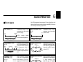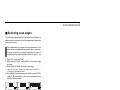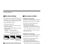
1
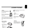
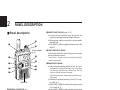
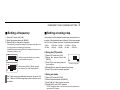
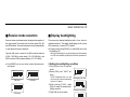
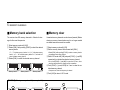
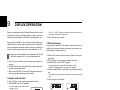
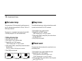
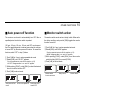
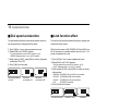
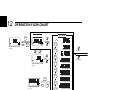
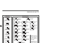
INSTRUCTION MANUAL
COMMUNICATIONS RECEIVER
iR2
This device complies with Part 15 of the FCC rules. Operation is subject to the following two conditions: (1) This device may not cause
harmful interference, and (2) this device must accept any interference
received, including interference that may cause undesired operation.
FOREWORD
CAUTIONS
READ ALL INSTRUCTIONS carefully and completely
R WARNING! NEVER operate the receiver with a headset or other audio accessories at high volume levels. Hearing
experts advise against continuous high volume operation. If
you experience a ringing in your ears, reduce the volume level
or discontinue use.
before using the receiver.
SAVE THIS INSTRUCTION MANUAL — This instruction manual contains important operating instructions for
the IC-R2.
AVOID using or placing the receiver in direct sunlight or in
EXPLICIT DEFINITIONS
The explicit definitions below apply to this instruction manual.
WORD
R WARNING
CAUTION
NOTE
DEFINITION
Personal injury, fire hazard or electric
shock may occur.
Equipment damage may occur.
If disregarded, inconvenience only. No risk
of personal injury, fire or electric shock.
Versions of the IC-R2 which display “CE” on the serial number
seal, comply with the essential requirements of the 89/336/EEC
directive for Electromagnetic Compatibility.
i
areas with temperatures below –10°C (+14°F) or above
+60°C (+140°F).
Even when the receiver power is OFF, a slight current still
flows in the circuits. Remove batteries from the receiver when
not using it for a long time. Otherwise, the installed batteries
will become exhausted.
For U.S.A. only
CAUTION: Changes or modifications to this device, not expressly approved by Icom Inc., could void your authority to
operate this device under FCC regulations.
SUPPLIED ACCESSORIES
OPERATING THEORY
Accessories included with the receiver:
Qty.
q Antenna (FA-S270C) ...................................................... 1
w Handstrap ....................................................................... 1
e Belt clip ........................................................................... 1
r Ni-Cd charger (BC-127A/D) and 2 Ni-Cd batteries .. 1 set*
Electromagnetic radiation which has frequencies of 20,000
Hz (20 kHz*) and above is called radio frequency (RF) energy
because it is useful in radio transmissions. The IC-R2 receives RF energy from 0.495 MHz* to 1309.995 MHz and
converts it into audio frequency (AF) energy which in turn actuates a loudspeaker to create sound waves. AF energy is in
the range of 20 to 20,000 Hz.
* Not supplied with some versions.
q
w
e
* kHz is an abbreviation of kilohertz or 1000 hertz, MHz is abbreviation of megahertz or 1,000,000 hertz, where hertz is a unit of frequency.
OPERATING NOTES
r
The IC-R2 may receive its own oscillated frequency, resulting
in no reception or only noise reception, on some frequencies.
The IC-R2 may receive interference from extremely strong
signals on different frequencies or when using an external
high-gain antenna.
ii
TABLE OF CONTENTS
FOREWORD ...................................... i
EXPLICIT DEFINITIONS ................... i
CAUTIONS ......................................... i
SUPPLIED ACCESSORIES .............. ii
OPERATING THEORY ...................... ii
OPERATING NOTES ........................ ii
TABLE OF CONTENTS .................... iii
1 ACCESSORY ATTACHMENT ..... 1
2 PANEL DESCRIPTION .......... 2 – 5
■ Panel description ...................... 2
■ Function display ........................ 4
3 FREQUENCY AND CHANNEL
SETTING ................................ 6 – 8
■ VFO and memory channels ...... 6
■ Operating band selection .......... 6
■ Setting a frequency ................... 7
■ Setting a tuning step ................. 7
■ Selecting a memory channel .... 8
■ Lock function ............................ 8
■ Attenuator function ................... 8
4 BASIC OPERATION ............. 9 – 11
■ Receiving .................................. 9
■ Setting volume level ................ 10
■ Setting squelch level ............... 10
iii
■ Monitor function ...................... 10
■ Receive mode selection ......... 11
■ Display backlighting ................ 11
5 MEMORY CHANNELS ....... 12 – 14
■ General ................................... 12
■ Programming during selection 12
■ Programming after selection ... 13
■ Transferring memory contents
to another memory ................. 13
■ Memory bank selection .......... 14
■ Memory clear .......................... 14
6 SCAN OPERATION ............ 15 – 19
■ Scan types .............................. 15
■ Full/band/programmed scan ... 16
■ Memory (bank) scan ............... 16
■ Selecting scan edges ............. 17
■ Skip channel setting ............... 18
■ Scan resume condition ........... 18
■ Frequency skip function .......... 19
7 PRIORITY WATCH ............. 20 – 21
■ Priority watch types ................ 20
■ Priority watch operation .......... 21
8 SUBAUDIBLE TONE
OPERATION ....................... 22 – 23
■ Tone squelch operation .......... 22
■ Pocket beep operation ............ 23
■ Tone scan ............................... 23
9 DUPLEX OPERATION .............. 24
10 OTHER FUNCTIONS ......... 25 – 30
■ Set mode ................................ 25
■ Dial select step ....................... 26
■ Beep tones ............................. 26
■ Power saver ............................ 26
■ Auto power-off function ........... 27
■ Monitor switch action .............. 27
■ Dial speed acceleration .......... 28
■ Lock function effect ................. 28
■ Channel indication mode ........ 29
■ Cloning function ...................... 29
■ Partial reset ............................ 30
■ All reset ................................... 30
11 TROUBLESHOOTING .............. 31
12 OPERATION FLOW CHART.. 32 – 33
13 SPECIFICATIONS AND
OPTIONS ............................ 34 – 35
ACCESSORY ATTACHMENT
D Antenna
Insert the supplied antenna into the antenna connector and screw down the antenna as shown at right.
1
Keep battery contacts clean. It’s a good idea to clean battery terminals once a week.
D Belt clip
Keep the jack cover attached when jack
is not in use to avoid bad contacts from
dust and moisture.
Commercially available antennas may increase receiver performance. An optional AD-92SMA ANTENNA CONNECTOR
ADAPTER is available to connect an antenna with a BNC connector.
D Battery installation
q Remove the battery cover
from the receiver.
Conveniently attaches to
your belt.
Slide the belt clip into the
plastic loop on the back of
the receiver.
D Handstrap
Slide the handstrap through the loop
on the side of the belt clip as illustrated at right. Facilitates carrying.
w Install 2 R6 (AA) size alkaline, dry cell or Ni-Cd
batteries.
• Be sure to observe the correct polarity.
• Charge Ni-Cd batteries before use. (See the separate
BC-127A/D
instruction
sheet.)
1
2
PANEL DESCRIPTION
■ Panel description
!1
q
!0
Function display
(p. 4)
o
w
i
e
u
r
y
t
SPEAKER
q ANTENNA CONNECTOR (p. 1)
Connects the supplied antenna.
• An optional AD-92SMA is available for connecting an antenna
with a BNC connector.
2
w MONITOR SWITCH [SQL] (pgs. 10, 27)
➥ Push and hold to temporarily open the squelch and
monitor the operating frequency. (default behaviour)
➥ While pushing, rotate the tuning dial to set the squelch
threshold level.
➥ Push [FUNC] + [SQL] to toggle the attenuator circuit ON
and OFF.
e FUNCTION SWITCH [FUNC]
While pushing this switch, other switches and tuning dial
perform secondary functions.
• “Push [FUNC] + a switch” means “while pushing the [FUNC]
switch, push the switch.”
r BAND SWITCH [BAND]
➥ Push to select the operating band (VHF, UHF, etc.). (p. 6)
• Broadcast band, HF band, 50 MHz band, VHF avionics band,
144 MHz band, 300 MHz band, 400 MHz band, 800 MHz
band and 1200 MHz band can be selected.
• While pushing this switch, rotating [DIAL] also selects the operating band.
➥ Transfers the displayed frequency to the VFO in memory mode. (p. 6)
➥ Push [FUNC] + [BAND] to enter the scan edge set mode
in VFO mode. (p. 17)
➥ Push [FUNC] + [BAND] to enter the bank scan set mode
in memory mode. (p. 16)
PANEL DESCRIPTION
t VOLUME CONTROL SWITCHES [VOL Y]/[VOL Z]
➥ Push to adjust the audio level. (p. 10)
➥ Push [FUNC] + either switch to start a scan. (p. 16)
➥ Push [FUNC] + either switch for 2 sec. to start a tone
scan. (p. 23)
y VFO/MEMORY SWITCH [V/M (MW)]
➥ Toggles between VFO and memory modes. (p. 6)
➥ Enters set mode when pushed for 2 sec. (p. 25)
➥ Push [FUNC] + [(V/M) MW] to enter memory write mode.
(p. 12)
➥ Push [FUNC] + [(V/M) MW] for 1 sec. to write the operating frequency into the selected memory channel in VFO
mode. Keep pushing for 2 sec. or more to automatically
select the next memory channel, if desired. (p. 12)
➥ Push [FUNC] + [(V/M) MW] for 1 sec. to write the displayed frequency into the VFO in memory mode. (p. 13)
u POWER SWITCH [POWER]
Push for 2 sec. to toggle the receiver power ON and OFF.
i TUNING STEP/MEMORY SKIP SWITCH [TS (SKIP)]
➥ Enters tuning step set mode. (p. 7)
➥ Push [FUNC] + [(TS) SKIP] to toggle the frequency skip
function ON or OFF in VFO mode. (p. 19)
➥ Push [FUNC] + [(TS) SKIP] for 2 sec. to program the displayed frequency as a skip frequency during full, band
or programmed scan. (p. 19)
2
➥ Push [FUNC] + [(TS) SKIP] to toggle the channel as skip,
program skip or non-skip channel in memory mode. (p.
18)
o MODE/LOCK SWITCH [MODE (LOCK)]
➥ Selects the receive mode. (p. 11)
➥ Push [FUNC] + [(MODE) LOCK] to toggle the lock function
ON and OFF. (pgs. 8, 28)
!0 EXTERNAL SPEAKER JACK [SP]
Connects an optional earphone or headphone. The internal speaker will not function when any external equipment
is connected. (See p. 35 for a list of available options.)
!1 TUNING DIAL [DIAL]
➥ Rotate [DIAL] to set operating frequencies, memory
channels, set mode contents, etc. (p. 7)
➥ While scanning, changes the scanning direction. (p. 16)
➥ While pushing [SQL], sets the squelch level. (p. 10)
➥ While pushing [FUNC], sets the operating frequency in
100 kHz, 1 MHz or 10 MHz steps in VFO mode. (pgs. 7,
26)
➥ While pushing [FUNC], selects memory bank in memory mode. (p. 12)
➥ While pushing [BAND], selects the operating band in
VFO mode. (p. 6)
3
2
PANEL DESCRIPTION
■ Function display
q
w
AMWFM
!4
!3
e
BUSY
!2
r
DUPTSQL
PRIOPSKIP MR
5
9
e TONE INDICATORS (p. 22)
➥ “T SQL” appears when the tone squelch function is activated and “T SQL ë” appears during pocket beep operation.
➥ “ë” flashes when the correct tone is received during
pocket beep operation.
ATT
75
50
25
3
2
1
t
y
!1 !0 o i u
q RECEIVE MODE INDICATORS (p. 11)
Show the receive mode.
• AM, FM and WFM are available.
w DUPLEX INDICATORS (p. 24)
Appear when semi-duplex operation (repeater operation)
is in use.
• “– DUP” appears when minus duplex is selected; “DUP” only, appears when plus duplex is selected.
4
r ATTENUATOR INDICATOR
Appears when the attenuator function is in use. (p. 8)
t FREQUENCY READOUT
Shows the operating frequency, set mode contents, etc.
• The smaller “75,” “50” and “25” to the right of the readout indicate
7.5, 5.0 and 2.5 kHz, respectively.
• The decimal point of the frequency flashes during scan.
y MEMORY CHANNEL READOUT
Shows the memory channel number, etc.
u MEMORY BANK INDICATORS
Indicate 8 memory banks.
• “1” – “3” indicate memory banks 1 to 3; “♦” indicates memory
bank 4; “♦1” – “♦3” indicate memory banks 5 to 7; no bank indicator indicates memory bank 0.
i MEMORY MODE INDICATOR
Appears when a memory channel is selected.
PANEL DESCRIPTION
2
o SKIP SCAN INDICATOR (p. 18)
➥ “SKIP” appears when a selected memory channel is set
as a skip channel in memory mode.
➥ “P SKIP” appears when the skip frequency function is
turned ON in VFO mode; or, when the selected memory
channel is set to be skipped during VFO scan (full, band
and programmed scan) in memory mode.
!0 SIGNAL INDICATORS
Shows the relative signal strength while receiving.
!1 PRIORITY WATCH INDICATOR (p. 20)
Appears when priority watch is in use.
!2 BUSY INDICATOR
“BUSY” appears when receiving a signal or when the
squelch is open.
!3 BATTERY INDICATORS
➥ Both segments appear when the batteries have enough
capacity.
➥ Only the right segment appears when the batteries are
nearing exhaustion.
➥ Flash when battery replacement is necessary.
!4 LOCK INDICATOR (p. 8)
Indicates that the lock function is in use.
5
3
FREQUENCY AND CHANNEL SETTING
■ VFO and memory channels
■ Operating band selection
This receiver has 2 normal operating modes: VFO mode and
memory mode.
The receiver can receive
the broadcast band, HF
band, 50 MHz band, VHF
avionics band, 144 MHz
band, 300 MHz band, 400
MHz band, 800 MHz band*
or 1200 MHz band.
➥ Push [BAND] several
times to select the desired band.
VFO mode is used for setting a desired frequency within the
frequency coverage.
FM
➥ Push [V/M] to select VFO mode.
Memory mode is used for operation of memory channels
which have programmed frequencies.
➥ Push [V/M] to select memory
FM
mode.
• To program a memory, refer to p. 12.
MR
“ MR ” appears.
What is VFO?
VFO is an abbreviation of Variable Frequency Oscillator. Frequencies for receiving are generated and controlled by the
VFO.
• When a memory channel
is selected, the first push
of [BAND] selects VFO
mode (and transfers the
memory channel contents).
➥ Rotate [DIAL] while
pushing [BAND] to select
the desired band.
* Some frequencies cannot be received with
the U.S.A. version.
AM
AM
1.625–29.995 MHz
BAND
FM
30–107.995 MHz
BAND
AM
108–135.995 MHz
BAND
FM
136–255.095 MHz
BAND
FM
BAND
255.1–382.095 MHz
FM
BAND
382.1–769.795 MHz
FM
BAND
6
0.495–1.620 MHz
BAND
769.8–960.095 MHz
FM
960.1–1309.995 MHz
FREQUENCY AND CHANNEL SETTING
3
■ Setting a frequency
■ Setting a tuning step
q Select VFO mode with [V/M].
w Select the desired band with [BAND].
e Rotate [DIAL] to change the frequency.
Tuning steps can be selected for each band, however, the tuning step of the broadcast band is fixed to 9 kHz steps except
for U.S.A. and Canada versions. The following are available.
• 5 kHz
• 6.25 kHz • 10 kHz • 12.5 kHz • 15 kHz
• 20 kHz • 25 kHz • 30 kHz • 50 kHz • 100 kHz
• The frequency changes according to the preset tuning steps. See
the right section for selecting the tuning step.
• Rotate [DIAL] while pushing [FUNC] to change the frequency in 1
MHz steps (default; p. 26).
FM
75
50
25
[DIAL] changes the frequency according
to the selected tuning step.
FM
75
50
25
While pushing [FUNC], [DIAL] changes
the frequency in 1 MHz steps (default).
The 1 MHz tuning step (dial select step) can be set to 100
kHz, 1 MHz or 10 MHz tuning steps in set mode. See p. 26
for details.
D Using the [TS] switch
q Select VFO mode with [V/M].
w Select the desired band with
[BAND].
e Push [TS] to enter tuning step set15 kHz tuning step
ting condition.
r Rotate [DIAL] to select the desired tuning step.
t Push [TS] to return to normal operation.
D Using set mode
q Select VFO mode with [V/M].
w Select the desired band with [BAND].
e Push [V/M] for 2 sec. to enter set mode.
r Rotate [DIAL] until “STEP” appears.
• “STEP” disappears after 1 sec. and the previously selected tuning step and “tS” appear.
t While pushing [FUNC], rotate [DIAL] to select the desired
tuning step.
y Push [V/M] to exit set mode.
7
3
FREQUENCY AND CHANNEL SETTING
■ Selecting a memory channel
■ Attenuator function
q Push [V/M] to select memory
mode.
The attenuator prevents a desired signal from distorting when
very strong signals are near the desired frequency or when
very strong electric fields, such as from a broadcasting station, are near your location.
FM
• “X” appears when a memory
channel is selected.
w Rotate [DIAL] to change the indicated memory channel.
• Only programmed memory channels can be selected.
• Rotate [DIAL] while pushing [FUNC]
to change the memory bank.
MR
[DIAL] changes the
memory channel.
FM
SKIP MR
3
2
1
While pushing [FUNC],
[DIAL] changes the
memory bank.
■ Lock function
The lock function prevents accidental frequency changes and
accidental function access.
➥ Push [FUNC] + [(MODE) LOCK] to toggle the lock function
ON and OFF.
• [POWER], [VOL] and [SQL] can still
be accessed while the lock function
is ON (default).
• Accessible switches can be set to 1
of 4 groups in expanded set mode.
See p. 28 for details.
8
The attenuator has approx. 10 dB attenuation.
➥ Push [FUNC] + [SQL] to toggle the attenuator function ON
and OFF.
FM
“ ” appears when the
lock function is in use.
Appears when the attenuator
function is in use.
FM
ATT
BASIC OPERATION
4
■ Receiving
Make sure charged Ni-Cd or alkaline batteries are installed.
(p. 1)
q Push [POWER] for 2 sec. to turn power ON.
w Push [VOL Y] or [VOL Z] to set the desired audio level.
r Push for setting
the squelch
(Push to monitor)
e Set frequency
r Set the squelch
level
e Select band
q Power switch
• The frequency display shows the volume level while setting. See
the next page for details.
e Set an operating frequency. (pgs. 6, 7)
r Set the squelch level.
• While pushing [SQL], rotate [DIAL].
• The first click of [DIAL] indicates the current squelch level.
• “LEVEL1” is loose squelch and “LEVEL9” is tight squelch.
• “AUTO” indicates automatic level adjustment with a noise pulse
count system.
• Push and hold [SQL] to open the squelch manually.
w Set volume
t When a signal is received:
➥ Squelch opens and audio is emitted from the speaker.
➥ The S/RF indicator shows the relative signal strength.
9
4
BASIC OPERATION
■ Setting volume level
■ Setting squelch level
The audio level can be adjusted through 32 levels.
➥ Push [VOL Y] or [VOL Z] to set the desired audio level.
The squelch circuit mutes the received audio signal depending on the signal strength. The receiver has 9 squelch levels,
a continuously open setting and an automatic squelch setting.
• Beep tone sounds while setting. This indicates the approximate
sound level.
• Pushing and holding these keys change the audio level continuously.
• The frequency display shows the volume level while setting.
INDICATION
AUDIO LEVEL
Min. setting (no audio)
:
Initial setting
:
➥ While pushing [SQL], rotate the
[DIAL] to select the squelch level.
• The first click of [DIAL] indicates the
current squelch level.
• “LEVEL1” is loose squelch and
“LEVEL9” is tight squelch.
• “AUTO” indicates automatic level adjustment with a noise pulse count
system.
• “OPEN” indicates continuously open
setting.
Automatic squelch
Maximum level
:
:
Max. setting
■ Monitor function
This function is used to listen to weak signals or to open the
tone squelch manually.
➥ Push and hold [SQL] to monitor the operating frequency.
The [SQL] switch can be set to ‘sticky’ operation in expanded set mode. (p. 27)
10
BASIC OPERATION
4
■ Receive mode selection
■ Display backlighting
Receive modes are determined by the physical properties of
the radio signals. The receiver has 3 receive modes: FM, AM
and WFM modes. The mode selection is stored independently
in each band and memory channels.
The receiver has display backlighting with a 5 sec. timer for
nighttime operation. The display backlighting can be turned
ON continuously or turned OFF, if desired.
➥ Push any switch except [FUNC]; or, rotate [DIAL] to turn the
backlighting ON.
Typically, AM mode is used for the AM broadcast stations
(0.495–1.620 MHz) and air band (118–135.995 MHz), and
WFM is used for FM broadcast stations (76–107.9 MHz).
• When auto backlighting is set, the backlighting will automatically
turn OFF when switches and [DIAL] have not been operated for 5
sec.
➥ Push [MODE] one or more times to select the desired receive mode.
FM
AM
FM mode
WFM
WFM mode
AM mode
D Setting the backlighting condition
q Push [V/M] for 2 sec. to enter set
mode.
w Rotate [DIAL] until “LIGHT” appears.
• “LIGHT” disappears after 1 sec. and
the previously selected backlighting
timer and “LI” appear.
e While pushing [FUNC], rotate
[DIAL] to select the desired backlighting condition.
r Push [V/M] to exit set mode.
Backlighting set mode
Automatic backlighting
Continuously OFF
11
5
MEMORY CHANNELS
■ General
■ Programming during selection
The receiver has 400 memory channels in 8 banks for storage of often-used frequencies.
q Select VFO mode with [V/M].
w Set the desired frequency:
➥ Select the desired band with [BAND].
➥ Set the frequency using [DIAL].
➥ Set other data (e.g. offset frequency, duplex direction,
tone squelch frequency, etc.), if required.
e Push [FUNC] + [(V/M) MW] momentarily to indicate memory
channels.
D Memory channel contents
The following information can be programmed into memory
channels:
• Operating frequency (p. 7)
• Receive mode (p. 11)
• Tuning step (p. 7)
• Duplex direction (DUP or – DUP) with an offset frequency
(p. 24)
• Tone squelch ON/OFF (p. 22)
• Tone squelch frequency (p. 22)
• Scan skip setting (p. 18)
• Do not hold [FUNC] + [(V/M) MW] for more than 0.5 sec., otherwise the previously selected memory channel will be overwritten.
r Rotate [DIAL] to select the desired channel.
• VFO (VF), as well as regular memory channels, can be programmed in this way.
• Rotate [DIAL] while pushing [FUNC] to select a memory bank,
programmed scan edge channel or VFO.
t Push [FUNC] + [(V/M) MW] for 1 sec. to program.
• Keep pushing for 2 sec. or more to automatically select the next
memory channel, if desired.
[EXAMPLE]: Programming ch 40 of memory bank 5 during selection.
FUNC
+
FUNC
FM
DUPTSQL
+
FUNC
+
FM
V/M MW
momentarily
V/M MW
MR
for bank for CH
selection selection
for 2 sec.
MR
1
blank channel
12
FM
DUPTSQL
MEMORY CHANNELS
■ Programming after selection
q Select memory mode with [V/M].
w Set the memory channel to be programmed with [DIAL].
• Rotate [DIAL] while pushing [FUNC] to select a memory bank or
programmed scan edge channel.
• Non-programmed channels cannot be selected.
e Push [V/M] to select VFO mode.
r Set the desired frequency:
➥ Select the desired band with [BAND].
➥ Set the frequency using [DIAL].
➥ Set other data (e.g. offset frequency, duplex direction,
tone squelch frequency, etc.), if required.
t Push [FUNC] + [(V/M) MW] for 1 sec. to program the selected channel.
• Keep pushing for 2 sec. or more to automatically select the next
memory channel, if desired.
5
■ Transferring memory
contents to another memory
q Select memory mode with [V/M].
w Select the memory channel to transfer with [DIAL].
• Rotate [DIAL] while pushing [FUNC] to select a memory bank or
programmed scan edge channel.
e Push [FUNC] + [(V/M) MW] momentarily to indicate memory
channels.
• Do not hold [FUNC] + [(V/M) MW] for more than 0.5 sec., otherwise the memory channel contents will be transferred to VFO.
r Rotate [DIAL] to select the channel to transfer to.
• Rotate [DIAL] while pushing [FUNC] to select a memory bank or
programmed scan edge channel.
• VFO (VF), as well as regular memory channels, can be transferred in this way.
t Push [FUNC] + [(V/M) MW] for 2 sec. to transfer.
[EXAMPLE]: Transferring memory channel 3 (memory bank 0) to 20 (memory bank 0).
FUNC
V/M MW
FUNC
+
+
V/M MW
V/M MW
FM
FM
FM
momentarily
Select memory
channel
MR
for 1 sec.
MR
MR
MR
blank channel
13
5
MEMORY CHANNELS
■ Memory bank selection
■ Memory clear
The receiver has 400 memory channels in 8 banks for storage of often-used frequencies.
Unwanted memory channels can be cleared (erased). Before
clearing a memory channel make sure it is no longer needed
as cleared memories cannot be recalled.
q Select memory mode with [V/M].
w Rotate [DIAL] while pushing [FUNC] to select the desired
memory banks.
• “1” – “3” indicate memory banks 1 to 3; “♦” indicates memory
bank 4; “♦1” – “♦3” indicate memory banks 5 to 7; no bank indicator indicates memory bank 0.
e Rotate [DIAL] to select the desired memory channel.
FM
FM
• Rotate [DIAL] while pushing [FUNC] to select a memory bank or
programmed scan edge channel.
e Select VFO mode with [V/M] and push [FUNC] + [(V/M) MW]
momentarily to indicate the selected memory channel.
• Do not hold [FUNC] + [(V/M) MW] for more than 0.5 sec., otherwise the selected memory channel will be overwritten.
FM
MR
MR
q Select memory mode with [V/M].
w Set the memory channel to be cleared with [DIAL].
MR
3
r Push [FUNC] + [(MODE) LOCK] for 2 sec. to clear the selected memory channel.
1
Memory bank 0
Memory bank 1
Memory bank 7
• 3 beeps sound, then the frequency is cleared.
t Push [V/M] to return to VFO mode.
[EXAMPLE]: Clearing memory channel 3 (memory bank 0).
FUNC
FUNC
+
+
V/M MW
V/M MW
FM
V/M MW
FM
MODE LOCK
FM
V/M MW
momentarily
Select memory
channel
14
MR
for 2 sec.
MR
MR
SCAN OPERATION
■ Scan types
Up to 25 programmed scan ranges, full scan, band scan and
memory bank scan provide scanning versatility. Each scan
can have skip channels programmed.
FULL SCAN (p. 16)
495
kHz
1309.995
MHz
Repeatedly scans all frequencies over the entire
receiver range.
SELECTED BAND SCAN
(p. 16)
Band
edge
Band
edge
U.S.A. version cannot
receive some frequencies.
Scan
Jump
PROGRAMMED SCAN
(p. 16)
Band
edge
Scan edges
Scan
Jump
FREQUENCY SKIP
FUNCTION (p. 19)
Band edge or
scan edge
Band edge or
scan edge
Scan
Skip
Skip
Jump
Repeatedly scans all frequencies over the entire
selected band.
Scan
Jump
Band
edge
6
Repeatedly scans between
two user-programmed frequencies. Used for checking
for frequencies within a
specified range such as
repeater output frequencies,
etc.
MEMORY (BANK) SCAN
(p. 16)
Not yet
Skips unwanted frequencies that inconveniently
stop scanning. This function can be turned ON and
OFF in frequency skip function set mode. ([FUNC] +
[(TS) SKIP])
MEMORY SKIP FUNCTION
(p. 18)
Not yet
programmed
ch 1
ch 2
ch 3
ch 49
ch 6
ch 5
ch 0
ch 4
SKIP
programmed
ch 1
ch 2
ch 3
ch 49
ch 6
ch 5
ch 0
Repeatedly scans memory
channels except skip channels within all programmed
channels or within a memory bank (0–7).
ch 4
Skips unwanted memory
channels that inconveniently stop scanning. Skip
channels can be toggled
ON and OFF by pushing
[FUNC] + [(TS) SKIP] in
memory mode.
15
6
SCAN OPERATION
■ Full/band/programmed scan
■ Memory (bank) scan
q Select VFO mode with [V/M].
w Make sure the squelch is set to the threshold point.
q Select memory mode with [V/M].
w Make sure the squelch is set to the threshold point.
• Select automatic squelch (AUTO) or a level (1–9) where the
noise is just muted. (p. 10)
• Select automatic squelch (AUTO) or a level (1–9) where the
noise is just muted. (p. 10)
e Select the desired scan range, if desired.
➥ Select scan edges in scan edge set mode:
“ALL” for full scan, “BAND” for band scan or “PROG 0”–
“PROG24” for programmed scan. (see the next page)
r Push [FUNC] + [Y] or [Z] momentarily to start the scan.
e Turn the memory bank scan ON or OFF in the memory
scan set mode, if desired.
• Decimal point flashes while scanning.
• “P SKIP” flashes when the frequency skip function is turned ON.
(p. 19)
• “0P”–“24P” flash to indicate which pair of scan edges is being
scanned.
• To change the scanning direction, rotate [DIAL].
• If the pocket beep function is activated, the receiver automatically
selects the tone squelch function when a scan starts.
• Decimal point flashes while scanning.
• To change the scanning direction, rotate [DIAL].
• If the pocket beep function is activated, the receiver automatically
selects the tone squelch function when a scan starts.
t To stop the scan, push [FUNC] + [Y] or [Z] again.
If the same frequencies are programmed into a pair of
scan edges, programmed scan does not start.
For programmed scan, scan edges must be programmed
in advance. Program scan edges in the same manner of
programming a memory channel and select a scan edge.
(p. 17)
16
• See below for details.
r Push [FUNC] + [Y] or [Z] momentarily to start the memory
(bank) scan.
t To stop the scan, push [FUNC] + [Y] or [Z] again.
D Memory bank selection
q Select memory mode with [V/M].
w While pushing [FUNC], push [BAND] to enter memory
scan set mode.
e Rotate [DIAL] to select the memory bank scan ON or OFF.
• “ALL” indicates all memory banks are
scanned (memory bank scan OFF);
“BANK” indicates memory bank scan
is turned ON.
r Push [BAND] to exit memory scan
set mode.
Bank scan ON
SCAN OPERATION
6
■ Selecting scan edges
The scanning range can be set to all frequencies (full scan), a
selected band or between two user-programmed frequencies
(programmed scan).
The programmed scan edges can be programmed in the
same manner as programming regular memory channels.
Program the desired scan edge frequencies in a pair of
programmed scan edge channels in advance. (pgs. 12, 13)
q Select VFO mode with [V/M].
w While pushing [FUNC], push [BAND] to enter band edge
set mode.
e Rotate [DIAL] to select the desired scan edge.
• “ALL” for full scan, “BAND” for band scan or “PROG 0” –
“PROG24” for programmed scan.
r Push [BAND] to exit band edge set mode; or push [FUNC]
+ [Y] or [Z] momentarily to start the programmed scan
using the selected edges.
Full scan
Band scan
Programmed scan 24
(Scan edge channels
24A and 24b)
17
6
SCAN OPERATION
■ Skip channel setting
■ Scan resume condition
Memory channels can be set to be skipped for memory skip
scan. In addition, memory channels can be set to be skipped
for both memory skip scan and frequency skip scan. These
are useful to speedup the scan interval.
D Setting the scan pause time
q Select memory mode with [V/M].
w Rotate [DIAL] to select a memory channel to be programmed as a skip channel.
e While pushing [FUNC], push [(TS) SKIP] one or more times
to select a condition.
• No indication
: channel will not be skipped.
• “SKIP” appears : channel skipped during memory scan.
• “P SKIP” appears : channel skipped during memory scan; frequency skipped during other scans.
FM
FM
MR
Non-skip channel
Skip channel
q Push [V/M] for 2 sec. to enter expanded set mode.
w Rotate [DIAL] until “PAUSE” appears.
• Turn the expanded set mode ON for selection. (p. 25)
e While pushing [FUNC], rotate [DIAL] to select the condition.
• “2SEC”–“20SEC”: scan pauses for 2–20 sec. on a received signal.
• “HOLD”: scan pauses on a received signal until it disappears.
r Push [V/M] to exit set mode.
D Setting the scan resume time
The scan restarts after a signal disappears according to the
resume time. It can be set from 0–5 sec. or unlimited.
FM
SKIP MR
The scan pauses when receiving signals according to the
scan pause time. It can be set from 2–20 sec. or unlimited.
PSKIP MR
Skip channel and
frequency skip channel
The frequency skip function is effective when the frequency skip function (P SCAN) is turned ON. See the next
page for details.
q Push [V/M] for 2 sec. to enter expanded set mode.
w Rotate [DIAL] until “RESUME” appears.
• Turn the expanded set mode ON for selection. (p. 25)
e While pushing [FUNC], rotate [DIAL] to select condition.
• “1SEC”–“5SEC”: scan restarts 1–5 sec. after the signal disappears.
• “0SEC”: scan restarts immediately after the signal disappears.
• “HOLD”: scan restarts by rotating [DIAL] only.
r Push [V/M] to exit set mode.
18
SCAN OPERATION
6
■ Frequency skip function
D Programming a skip frequency
D Frequency skip function ON/OFF
Unwanted frequencies can be skipped and programmed as
skip channels when full scan, band scan or programmed scan
is pausing.
The frequency skip function can be turned OFF. In this case,
the frequencies will not be skipped even if skip information is
programmed and “P SKIP” does not appear.
q Start full scan, band scan or programmed scan. (p. 16)
w While receiving an unwanted signal and scan pauses,
push [FUNC] + [(TS) SKIP] for 2 sec. to program the received frequency as a skip frequency.
q Select VFO mode with [V/M].
w Push [FUNC] + [(TS) SKIP] to toggle the frequency skip
function ON or OFF.
• The receiver emits 3 beeps and the scan resumes.
• Non-programmed memory channels (blank channels) are used
for skip frequency programming in reverse sequence.
• To scan the skip frequency after programming, cancel the skip
information (p. 18) or clear the memory channel (p. 14).
FM
FM
PSKIP
BUSY
5
Indication while pausing
PSKIP
BUSY
• “P SKIP” appears when the function is turned ON.
FM
FM
PSKIP
The frequency skip
function is OFF.
The frequency skip
function is ON.
3
5
Indication while programming
19
7
PRIORITY WATCH
■ Priority watch types
Priority watch checks for signals on a frequency every 5 sec.
while operating on a VFO frequency or scanning. The receiver
has 3 priority watch types to suit your needs.
In addition, you can be alerted with beeps and a flashing “ë.”
The watch resumes according to the selected scan resume
condition. See p. 18 for details.
If the pocket beep function is activated, the receiver automatically selects the tone squelch function when priority
watch starts.
MEMORY CHANNEL
WATCH
5 sec.
125 msec.
VFO
frequency
Memory
channel
• A memory channel with skip information can be watched.
MEMORY SCAN WATCH
While operating on a VFO
frequency, priority watch
checks for signals on each
memory channel in sequence.
125 msec.
5 sec.
VFO
frequency
SKIP
Mch 0
Mch 1
Mch 2
Mch 49
VFO SCAN WATCH
5 sec.
125 msec.
VFO
scanning
20
While operating on a VFO
frequency, priority watch
checks for a signal on the
selected memory channel
every 5 sec.
Memory
channel
• The memory skip function
and/or memory bank scan is
useful to speed up the scan.
While scanning in VFO
mode, priority watch checks
for signals on the selected
memory channel every 5
sec.
PRIORITY WATCH
7
■ Priority watch operation
D Memory channel watch and memory scan
watch
q Select VFO mode; then, set an operating frequency.
w Set the watching channel(s).
For memory channel watch:
Select the desired memory channel.
For memory scan watch:
Select memory mode; then, push [FUNC] + [Y] or [Z] momentarily to start memory scan.
e Push [V/M] for 2 sec. to enter set mode.
r Rotate [DIAL] until “PRIO” appears.
• “PRIO” disappears after 1 sec. and “OFF” and “PR” appear.
t While pushing [FUNC], rotate [DIAL] to select priority
watch ON or priority watch ON with alert.
y Push [V/M] to exit set mode and start the watch.
• The receiver checks the memory channel frequency every 5 sec.
• The watch resumes according to the selected scan resume condition. (p. 18)
u Push [V/M] while the display
shows the VFO frequency to stop
the watch.
FM
PRIO
MR
D VFO scan watch
q Select the desired memory channel to be watched.
w Push [V/M] to select VFO mode.
e Push [FUNC] + [Y] or [Z] momentarily to start full scan,
band scan or programmed scan. (p. 16)
r Push [V/M] for 2 sec. to enter set mode.
t Rotate [DIAL] until “PRIO” appears.
• “PRIO” disappears after 1 sec. and
“OFF” and “PR” appear.
y While pushing [FUNC], rotate
[DIAL] to select priority watch ON
or priority watch ON with alert.
u Push [V/M] to exit set mode and
start the watch.
• The receiver checks the memory
channel frequency every 5 sec.
• The watch resumes according to the
selected scan resume condition. (p.
18)
i Push [V/M] while the display
shows the VFO frequency to stop
the watch.
Priority watch set mode
Priority watch is ON.
Priority watch with
alert is ON.
While pausing on the
memory channel, “PRIO”
flashes.
21
8
SUBAUDIBLE TONE OPERATION
■ Tone squelch operation
D Operation
The tone squelch opens only when receiving a signal containing a matching subaudible tone. You can silently wait for
calls from group members using the same tone in an amateur band.
• See right for programming.
Tone function set mode
• Turn the expanded set mode ON for
Tone squelch is ON.
selection. (p. 25)
• “TSQL” disappears after 1 sec. and “tO” appears.
t While pushing [FUNC], rotate [DIAL] to select “TSQL.”
y Push [V/M] to exit set mode and start the tone squelch.
u When the received signal includes a matching tone,
squelch opens and the signal can be heard.
• When the received signal’s tone does not match, tone squelch
does not open, however, the S-indicator shows signal strength.
• To open the squelch manually, push and hold [SQL].
i To cancel the tone squelch, repeat steps e–y as described above and select “OFF” in step t.
22
q Select VFO mode or desired memory channel to be programmed.
w Push [V/M] for 2 sec. to enter expanded set mode.
e Rotate [DIAL] until “TONE” appears.
• Turn the expanded set mode ON for selection. (p. 25)
• “TONE” disappears after 1 sec. and “Ct” appears.
r While pushing [FUNC], rotate [DIAL] to select a subaudible
tone.
q Set the operating frequency.
w Set the desired subaudible tone in
expanded set mode.
e Push [V/M] for 2 sec. to enter expanded set mode.
r Rotate [DIAL] until “TSQL” appears.
D Setting subaudible tones for tone squelch
operation
• Each operating band and each memory channel have independent settings.
t Push [V/M] to exit set mode.
• Available subaudible tone frequencies
67.0
69.3
71.9
74.4
77.0
79.7
82.5
85.4
88.5
91.5
94.8
97.4
100.0
103.5
107.2
110.9
114.8
118.8
123.0
127.3
131.8
136.5
141.3
146.2
151.4
156.7
159.8
162.2
165.5
167.9
171.3
173.8
177.3
179.9
183.5
186.2
189.9
192.8
196.6
199.5
203.5
206.5
(unit: Hz)
210.7 250.3
218.1 254.1
225.7
229.1
233.6
241.8
➲ CONVENIENT
Store subaudible tone frequencies and tone squelch ON/OFF
settings in memories for easy recall.
SUBAUDIBLE TONE OPERATION
8
■ Pocket beep operation
■ Tone scan
This function uses subaudible tones for calling and can be
used as a “common pager” to inform you that someone has
called using the same tone in an amateur band while you
were away from the receiver.
The receiver can detect the subaudible tone frequency in a
received signal. By monitoring a signal that is being transmitted on a frequency, you can check the tone frequency required to access the repeater or to open the tone squelch.
D Waiting for a call from a specific station
q Set the desired frequency or memory channel to be
checked for a tone frequency.
w Push [FUNC] + [Y] or [Z] for 2 sec. to start the tone scan.
q Set the operating frequency.
w Set the desired tone squelch tone in expanded set mode.
• See the previous page for programming information.
e Push [V/M] for 2 sec. to enter expanded set mode.
r Rotate [DIAL] until “TSQL” appears.
• Turn the expanded set mode ON for selection. (p. 25)
• “TSQL” disappears after 1 sec. and “tO” appears.
t While pushing [FUNC], rotate [DIAL] to select “P BEEP.”
y Push [V/M] to exit set mode and start the pocket beep.
• “T SQL ë” appears in the function display.
u When a signal with the correct tone is received, the receiver emits beep tones for 30 sec. and flashes “ë.”
i Push [V/M] to stop the beeps and flashing.
• Tone squelch is automatically selected.
The receiver has 50 tone frequencies and consequently
their spacing is narrow compared with units having 38
tones. Therefore, some tone frequencies may receive interference from adjacent tone frequencies.
• To change the scanning direction, rotate [DIAL].
e When the tone frequency is decoded, the set mode contents are programmed with the tone frequency.
• The tone scan pauses when a tone frequency is detected.
• The decoded tone frequency is used for the tone squelch frequency.
• “Ct” appears during tone scan.
r Push [FUNC] + [Y] or [Z] to stop the scan.
Tone frequencies
flash as they are
scanned.
T
“Ct” appears during
tone scan.
23
9
DUPLEX OPERATION
Duplex communication uses 2 different frequencies for transmitting and receiving. Generally, duplex is used in communication through a repeater, some utility communications, etc.
During duplex operation, the transmit station frequency is
shifted from the receive station frequency by the offset frequency. Repeater information (offset frequency and shift direction) can be programmed into memory channels. (p. 12)
This function is not available in the broadcast band (0.495
– 1.620 MHz) except for U.S.A. and Canada versions.
q Set the receive station frequency (repeater output frequency).
w Set the shift direction and offset of the transmit station frequency as described below.
e Push and hold [SQL] to monitor the transmit station frequency (repeater input frequency) directly.
D Duplex shift direction
• “–DUP” or “+DUP” indicates the transmit station frequency for
minus shift or plus shift, respectively.
r Push [V/M] to exit set mode.
D Offset frequency
During duplex operation, the transmit station frequency is
shifted from the receive station frequency by an amount determined by the offset frequency.
q Select VFO mode or desired memory channel to be programmed.
w Push [V/M] for 2 sec. to enter expanded set mode.
e Rotate [DIAL] until “OFFSET” appears.
• Turn the expanded set mode ON for selection. (p. 25)
• “OFFSET” disappears after 1 sec. and “OW” appears.
r While pushing [FUNC], rotate [DIAL] to set the desired offset.
• The offset frequency changes according to the selected tuning
step.
t Push [V/M] to exit set mode.
q Push [V/M] for 2 sec. to enter expanded set mode.
w Rotate [DIAL] until “DUP” appears.
• Turn the expanded set mode ON for
selection. (p. 25)
• “DUP” disappears after 1 sec. and
“dP” appears.
24
e While pushing [FUNC], rotate
[DIAL] to select “– DUP” or “+DUP.”
Offset frequency set mode
Minus shift
0.6 MHz (600 kHz) offset
OTHER FUNCTIONS
■ Set mode
D Set mode items
Set mode is used for programming infrequently changed values or conditions of functions.
In addition, this receiver has an expanded set mode which is
used for programming additional infrequently changed values
or conditions of functions. When turning OFF the expanded
set mode, only a quarter of the set mode items are displayed
for simpler operation.
D Expanded set mode ON/OFF
q Push [V/M] for 2 sec. to enter set mode.
w Rotate [DIAL] clockwise until “EXPAND” appears.
• “EXPAND” disappears after 1 sec. and “EX” appears.
e While pushing [FUNC], rotate [DIAL] to turn the expanded
set mode ON or OFF.
r Push [V/M] to exit set mode or rotate [DIAL] to select a set
mode item.
B
Tuning step
(p. 7)
Confirmation
beep (p. 26)
B
Dial select step
(p. 26)
Backlighting
(p. 11)
E
Tone squelch
(p. 22)
E
Auto power OFF
(p. 27)
E
Tone squelch
tone (p. 22)
E
Power save
(p. 26)
E
B
Duplex direction E
(p. 24)
Monitor switch
action (p. 27)
E
B
Offset frequency E
(p. 24)
Dial speed
(p. 28)
E
Scan resume
time (p. 18)
E
Lock function
effect (p. 28)
E
Scan pause
time (p. 18)
E
Channel indication
mode (p. 29)
Priority watch
(p. 21)
Expanded set mode setting
10
Expanded set mode ON
Expanded set
mode (p. 25)
E: Appears when expanded set mode is ON.
B: Does not appear within the broadcast band (0.495 – 1.620 MHz)
except for U.S.A. and Canada versions.
25
10
OTHER FUNCTIONS
■ Dial select step
■ Beep tones
This receiver has a 1 MHz tuning step for quick frequency setting. This dial select step can be set to 100 kHz, 1 MHz or 10
MHz steps, as desired.
The confirmation beep tones, which sound each time a switch
is pushed, can be turned ON or OFF, as desired.
This function is not available to the broadcast band (0.495 –
1.620 MHz) except for U.S.A. and Canada versions.
q Push [V/M] for 2 sec. to enter set mode.
w Rotate [DIAL] until “BEEP” appears.
• “BEEP” disappears after 1 sec. and “bE” appears.
e While pushing [FUNC], rotate [DIAL] to turn the confirmation beep ON or OFF.
r Push [V/M] to exit set mode.
D Setting dial select step
q Select VFO mode with [V/M].
w Push [V/M] for 2 sec. to enter set mode.
e Rotate [DIAL] until “D SEL” appears.
• “D SEL” disappears after 1 sec. and “dS” appears.
r While pushing [FUNC], rotate [DIAL] to select the desired
dial select step.
• 100 kHz, 1 MHz and 10 MHz steps can be selected.
■ Power saver
The power saver function reduces the current drain to conserve battery power.
t Push [V/M] to exit set mode.
q Push [V/M] for 2 sec. to enter expanded set mode.
w Rotate [DIAL] until “P SAVE” appears.
• Turn the expanded set mode ON for selection. (p. 25)
• “P SAVE” disappears after 1 sec. and “PS” appears.
100 kHz step
26
1 MHz step
10 MHz step
e While pushing [FUNC], rotate [DIAL] to turn the power
saver ON (AUTO) or OFF.
r Push [V/M] to exit set mode.
OTHER FUNCTIONS
10
■ Auto power-off function
■ Monitor switch action
The receiver can be set to automatically turn OFF after a
specified period in which no switch is pushed.
The monitor switch can be set as a ‘sticky’ switch. When set to
the sticky condition, each push of [SQL] toggles the monitor
function on and off.
120 min., 90 min., 60 min., 30 min. and OFF can be specified. The specified period is retained even when the receiver
is turned OFF by the auto power-off function. To cancel the
function, select “OFF” in step e below.
q Push [V/M] for 2 sec. to enter expanded set mode.
w Rotate [DIAL] until “MONI” appears.
q Push [V/M] for 2 sec. to enter expanded set mode.
w Rotate [DIAL] until “AP OFF” appears.
e While pushing [FUNC], rotate [DIAL] to set the monitor
switch to sticky (HOLD) or normal (PUSH).
r Push [V/M] to exit set mode.
• Turn the expanded set mode ON for selection. (p. 25)
• “AP OFF” disappears after 1 sec. and “AO” appears.
• Turn the expanded set mode ON for selection. (p. 25)
• “MONI” disappears after 1 sec. and “mO” appears.
e While pushing [FUNC], rotate [DIAL] to select the desired
time or to turn the function OFF.
r Push [V/M] to exit set mode.
Monitor switch
function set mode
Auto power off set
mode
60 min. auto power-off
‘Sticky’ action
‘Normal’ action
Auto power-off is
turned OFF.
27
10
OTHER FUNCTIONS
■ Dial speed acceleration
■ Lock function effect
The dial speed acceleration automatically speeds up the tuning dial speed when rotating the [DIAL] rapidly.
The lock function prevents accidental frequency changes and
accidental function access.
q Push [V/M] for 2 sec. to enter expanded set mode.
w Rotate [DIAL] until “SPEED” appears.
While the lock function is ON, [POWER], [VOL] and [SQL] can
still be accessed. Accessible switches can be set to 1 of 4
groups in expanded set mode.
• Turn the expanded set mode ON for selection. (p. 25)
• “SPEED” disappears after 1 sec. and “SP” appears.
e While pushing [FUNC], rotate [DIAL] to set the dial speed
acceleration ON or OFF.
r Push [V/M] to exit set mode.
q Push [V/M] for 2 sec. to enter expanded set mode.
w Rotate [DIAL] until “LOCK” appears.
• Turn the expanded set mode ON for selection. (p. 25)
• “LOCK” disappears after 1 sec. and “Lk” appears.
e While pushing [FUNC], rotate [DIAL] to select the accessible switches.
Dial speed acceleration
set mode
Dial speed
acceleration ON
Dial speed
acceleration OFF
• “NORMAL”
• “NO SQL”
• “NO VOL”
• “ALL”
:[POWER], [VOL] and [SQL] are accessible.
:[POWER] and [SQL] are accessible.
:[POWER] and [VOL] are accessible.
:[POWER] is accessible.
r Push [V/M] to exit set mode.
Lock function effect
set mode
28
[POWER], [VOL]
and [SQL] are
accessible.
[POWER] is
accessible.
OTHER FUNCTIONS
10
■ Channel indication mode
■ Cloning function
Channel indication mode is used to simplify operation. In this
mode only pre-programmed memory channel numbers are
displayed and functions are limited ([POWER], [SQL], [VOL],
[LOCK], scanning and the tuning dial are functional).
The IC-R2 has receiver-to-receiver data cloning capability.
This function is useful when you want to copy all of the programmed contents from one IC-R2 to another. An optional
OPC-474 CLONING CABLE is required.
q Select memory mode with [V/M].
w Push [V/M] for 2 sec. to enter expanded set mode.
e Rotate [DIAL] until “CH” appears.
The optional CS-R2 CLONING SOFTWARE and the optional
OPC-478 CLONING CABLE are available to clone and edit
contents using a PC.
• Turn the expanded set mode ON for selection. (p. 25)
r While pushing [FUNC], rotate [DIAL] to turn the channel
indication ON or OFF.
t Push [V/M] to exit set mode.
• To return to normal indication, turn this function OFF in
step r above.
• Frequencies must be programmed into memory channels
in advance.
FM
Channel indication
mode set mode
Channel indication
mode ON
q While pushing [TS], [V/M] and [Y], push [POWER] for 1
sec. to enter cloning mode.
• “CLONE” appears.
w Connect an optional OPC-474 between both [SP] jacks.
e Push [SQL] on the “master” receiver (receiver-toOPC-474
receiver cloning only).
• “CL OUT” appears and the
signal indicator shows that
cloning is taking place.
Channel indication
mode example
(Memory ch 49 of
memory bank 7)
29
10
OTHER FUNCTIONS
■ Partial reset
If you want to initialize the operating conditions (VFO frequency, VFO settings, set mode contents) without clearing the
memory contents, a partial resetting function is available for
the receiver.
➥ While pushing [FUNC] and [V/M], turn power ON to partially reset the receiver.
■ All reset
Reset the CPU before operating the receiver for the first time,
or when the internal CPU malfunctions.
➥ While pushing [FUNC], [BAND] and [V/M], turn power ON
to reset the CPU.
• “CLEAR” appears when resetting the CPU.
CAUTION: Resetting the CPU returns all programmed
contents to their default settings.
30
TROUBLESHOOTING
11
If your receiver seems to be malfunctioning, please check the
following points before sending it to a service center.
PROBLEM
POSSIBLE CAUSE
SOLUTION
REF.
No power comes ON.
• The batteries are exhausted.
• The battery polarity is reversed.
• Replace the batteries.
• Check the battery polarity.
p. 1
p. 1
No sound comes from the
speaker.
• Volume level is too low.
• Different tone is selected with tone squelch.
• Push [VOL Y] to obtain a suitable level.
• Check the tone using tone scan.
p. 10
p. 23
Frequency cannot be set.
• The lock function is activated.
• Channel indication mode is selected.
• Push [FUNC] + [(MODE)LOCK] to cancel the function.
• Turn the channel indication mode OFF in set mode.
p. 8
p. 29
No beeps sound.
• Beep tones are turned OFF.
• Turn beep tones ON in set mode.
p. 26
Receive audio is
distorted.
• The operating mode is not selected correctly.
• Select a suitable operating mode in set mode.
p. 11
Desired set mode item
cannot be selected.
• The desired set mode item is in expanded set
mode.
• Some set mode items cannot be selected in
the broadcast band.
• Turn the expanded set mode ON.
p. 25
• Choose a band other than the broadcast band.
p. 25
31
12
OPERATION FLOW CHART
Memory mode
BAND
VFO mode
V/M MW
FM
MR
FUNC
+
V/M MW
BAND
0.495–1.620 MHz
BAND
Bank scan set mode
(p. 16)
V/M MW
TS SKIP
BAND
TS SKIP
1.625–29.995 MHz
for 2 sec.
TS SKIP
BAND
30–107.995 MHz
momentarily
TS SKIP
BAND
Tuning step set mode
(p. 7)
BAND
BAND
108–135.995 MHz
136–255.095 MHz
255.1–382.095 MHz
BAND
BAND
FUNC
Scan edge set mode
(p. 17)
+
382.1–769.795 MHz
BAND
BAND
769.8–960.095 MHz
960.1–1309.995 MHz
32
V/M MW
OPERATION FLOW CHART
12
Expanded set mode
Set mode
TSQL
Tone squelch
tone (p. 22)
Expanded set
mode (p. 25)
Expanded set mode (p. 25)
B Duplex
direction (p. 24)
Channel
indication mode
(p. 29)
Backlighting (p. 11)
Confirmation beep (p. 26)
Lock function
effect (p. 28)
B Offset
frequency
(p. 24)
Dial speed
(p. 28)
Scan resume
time (p. 18)
Monitor switch
action (p. 27)
Scan pause
time (p. 18)
Power save
(p. 26)
Priority watch
(p. 21)
Auto power
OFF (p. 27)
Confirmation
beep (p. 26)
Tone squelch
(p. 22)
B Dial select
step (p. 26)
B Tuning step
(p. 7)
Priority watch (p. 21)
B Dial select step (p. 26)
B Tuning step (p. 7)
Backlighting
(p. 11)
Displays for set and expanded set modes show
the default settings (except the expanded set
mode setting).
Rotate [DIAL] while pushing [FUNC] to change the
set mode condition.
B: Does not appear within the broadcast band (0.495 – 1.620 MHz).
33
13
SPECIFICATIONS AND OPTIONS
D General
• Frequency coverage
U.S.A. version
Non-U.S.A. versions
• Mode
• No. of memory channels
D Receiver
:
(unit: MHz)
0.495–823.995, 849–868.995,
894–1309.995
0.495–1309.995
: FM, AM, WFM
: 450
(400 regular, 50 scan edges)
• Usable temp. range
• Tuning steps
: –10°C to +60°C;
+14°F to +140°F
: 5, 6.25, 9,* 10, 12.5, 15, 20,
25, 30, 50 and 100 kHz
* Fixed tuning step while 0.495–1.620 MHz is selected except
for U.S.A. and Canada versions.
• Frequency stability
: ±6 ppm (–10°C to +60°C)
• Power supply requirement : 2 AA(R6) Ni-Cd or
(negative ground)
alkaline cells
• Current drain (at 3.0 V DC) :
Rated audio
170 mA typ.
Standby
100 mA typ.
Power saved
41 mA typ.
• Antenna connector
: SMA (50 Ω)
• Dimensions
: 58(W)×86(H)×27(D) mm;
(projections not included)
29⁄32(W)×33⁄8(H)×11⁄16(D) in
• Weight
: 170 g; 6 oz
(w/antenna and battery)
34
• Receive system
: Triple-conversion
superheterodyne
• Intermediate frequencies : 1st
266.7 MHz
2nd
19.65 MHz
3rd
450 kHz
• Sensitivity (except spurious points; typical):
FM
1.625–5.000 MHz
(at 12 dB SINAD)
5.005–29.995 MHz
30–117.995 MHz
118–174.995 MHz
175–329.995 MHz
330–429.995 MHz
430–450 MHz
450.005–469.995 MHz
470–999.995 MHz
1000–1309.995 MHz
WFM
76–108.0 MHz
(at 12 dB SINAD)
175–221.995 MHz
470–770.0 MHz
AM (at 10 dB S/N)
0.495–5.0 MHz
5.005–30.0 MHz
118–136.0 MHz
222–246.995 MHz
247–329.995 MHz
0.4 µV
0.25 µV
0.2 µV
0.18 µV
0.22 µV
0.25 µV
0.22 µV
0.25 µV
0.28 µV
0.45 µV
0.71 µV
0.71 µV
1.0 µV
1.3 µV
0.79 µV
0.63 µV
0.63 µV
0.71 µV
SPECIFICATIONS AND OPTIONS
• Selectivity
FM, AM
WFM
• Audio output power
(at 3.0 V DC)
• SP connector
:
More than 15 kHz/–6 dB
Less than 30 kHz/–60 dB
More than 150 kHz/–6 dB
: 100 mW typ. at 10% distortion
with an 8 Ω load
: 3-conductor 3.5 (d) mm
(1⁄8˝)/8 Ω
D Options
13
AD-92SMA ANTENNA CONNECTOR ADAPTER
Allows you to connect an antenna with a BNC connector.
(SMA to BNC adapter)
CS-R2 CLONING SOFTWARE + OPC-478 CLONING
CABLE
Allows you to transfer data from memories, etc. and quickly
and easily edit and store data via a PC.
OPC-474 CLONING CABLE
Used for handheld-to-handheld cloning.
BC-127A/D BATTERY CHARGER
Regularly charges 2 or 4 AA (R6) Ni-Cd batteries. 2 Ni-Cd
batteries are supplied with the BC-127A/D.
LC-146 CARRYING CASE
Helps protect the receiver from scratches, etc.
SP-13 EARPHONE
Provides clear receive audio in noisy environments.
HP-4 HEADPHONE
Provides increased readability of signals in noisy environments and listening privacy.
All stated specifications are subject to change without
notice or obligation.
35
Count on us!
A-5520H-1EX
Printed in Japan
© 1998 Icom Inc.
6-9-16 Kamihigashi, Hirano-ku, Osaka 547-0002 Japan