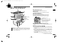
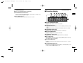
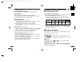
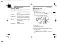
1
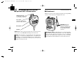
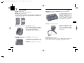
!IC-F50_F60 BIIS.qxd
03.9.12 8:49 AM
Page A (1,1)
INSTRUCTION MANUAL
VHF TRANSCEIVER
iF50
iF60
UHF TRANSCEIVER
This device complies with Part 15 of
the FCC rules. Operation is subject to
the condition that this device does not
cause harmful interference.
!IC-F50_F60 BIIS.qxd
03.9.12 8:49 AM
Page i (1,1)
SAFETY TRAINING INFORMATION
Your Icom radio generates RF electromagnetic energy
during transmit mode. This radio is designed for and classified as “Occupational Use Only”, meaning it must be
used only during the course of employment by individuals
aware of the hazards, and the ways to minimize such hazW ARN ING ards. This radio is NOT intended for use by the “General
Population” in an uncontrolled environment.
This radio has been tested and complies with the FCC RF exposure limits for “Occupational Use Only”. In addition, your Icom radio complies with
the following Standards and Guidelines with regard to RF energy and
electromagnetic energy levels and evaluation of such levels for exposure
to humans:
• FCC OET Bulletin 65 Edition 97-01 Supplement C, Evaluating Compliance with FCC Guidelines for Human Exposure to Radio Frequency Electromagnetic Fields.
• American National Standards Institute (C95.1-1992), IEEE Standard
for Safety Levels with Respect to Human Exposure to Radio Frequency Electromagnetic Fields, 3 kHz to 300 GHz.
• American National Standards Institute (C95.3-1992), IEEE Recommended Practice for the Measurement of Potentially Hazardous Electromagnetic Fields– RF and Microwave.
• The following accessories are authorized for use with this product.
Use of accessories other than those specified may result in RF exposure levels exceeding the FCC requirements for wireless RF exposure.; Belt Clip (MB-98), Rechargeable Li-Ion Battery Pack
(BP-227), Alkaline Battery Case (BP-226) and Speaker-microphone
(HM-138).
• DO NOT operate the radio without a proper antenna attached, as this
may damaged the radio and may also cause you to exceed FCC RF
exposure limits. A proper antenna is the antenna supplied with this
radio by the manufacturer or antenna specifically authorized by the
manufacturer for use with this radio.
• DO NOT transmit for more than 50% of total radio use time (“50%
duty cycle”). Transmitting more than 50% of the time can cause FCC
RF exposure compliance requirements to be exceeded. The radio is
transmitting when the “TX indicator” lights red. You can cause the
radio to transmit by pressing the “PTT” switch.
• ALWAYS keep the antenna at least 2.5 cm (1 inch) away from the
body when transmitting and only use the Icom belt-clip which is listed
on page vi when attaching the radio to your belt, etc., to ensure FCC
RF exposure compliance requirements are not exceeded. To provide
the recipients of your transmission the best sound quality, hold the
antenna at least 5 cm (2 inches) from your mouth, and slightly off to
one side.
The information listed above provides the user with the information
needed to make him or her aware of RF exposure, and what to do to assure that this radio operates with the FCC RF exposure limits of this radio.
To ensure that your expose to RF electromagnetic
energy is within the FCC allowable limits for occupational use, always adhere to the following guidelines:
Occupational/Controlled Use
The radio transmitter is used in situations in which persons are exposed
as consequence of their employment provided those persons are fully
aware of the potential for exposure and can exercise control over their
exposure.
C AU TIO N
i
Electromagnetic Interference/Compatibility
During transmissions, your Icom radio generates RF energy that can possibly cause interference with other devices or systems. To avoid such interference, turn off the radio in areas where signs are posted to do so.
DO NOT operate the transmitter in areas that are sensitive to electromagnetic radiation such as hospitals, aircraft, and blasting sites.
ii
!IC-F50_F60 BIIS.qxd
03.9.12 8:49 AM
Page iii (1,1)
FOREWORD
PRECAUTION
READ ALL INSTRUCTIONS carefully and completely before
R WARNING! NEVER hold the transceiver so that the antenna
using the transceiver.
is very close to, or touching exposed parts of the body, especially
the face or eyes, while transmitting. The transceiver will perform
best if the microphone is 5 to 10 cm (2 to 4 inches) away from the
lips and the transceiver is vertical.
SAVE THIS INSTRUCTION MANUAL— This instruction
manual contains important operating instructions for the IC-F50 VHF
TRANSCEIVER and IC-F60 UHF TRANSCEIVER.
R WARNING! NEVER operate the transceiver with a headset
or other audio accessories at high volume levels.
EXPLICIT DEFINITIONS
WORD
DEFINITION
RWARNING
Personal injury, fire hazard or electric shock
may occur.
CAUTION
NOTE
BP-226 or BP-227. Such a connection will ruin the transceiver.
DO NOT push the PTT when not actually desiring to transmit.
AVOID using or placing the transceiver in direct sunlight or in
Equipment damage may occur.
areas with temperatures below –30°C (–22°F) or above +60°C
(+140°F).
If disregarded, inconvenience only. No risk
of personal injury, fire or electric shock.
DO NOT modify the transceiver for any reason.
MAKE SURE the flexible antenna and battery pack are securely
OPERATING NOTES
• When transmitting with a portable radio, hold the radio in a vertical
position with its microphone 5 to 10 centimeters (2 to 4 inches)
away from your mouth. Keep the antenna at least 2.5 centimeters
(1 inch) from your head and body.
• If you wear a portable two-way radio on your body, ensure that the
antenna is at least 2.5 centimeters (1 inch) from your body when
transmitting.
iii
CAUTION! NEVER short the terminals of the battery pack.
NEVER connect the transceiver to a power source other than the
attached to the transceiver, and that the antenna and battery pack
are dry before attachment. Exposing the inside of the transceiver
to water will result in serious damage to the transceiver.
The use of non-Icom battery packs/chargers may impair transceiver
performance and invalidate the warranty.
FCC caution:
Changes or modifications to this device, not expressly approved
by Icom Inc., could void your authority to operate this transceiver
under FCC regulations.
iv
!IC-F50_F60 BIIS.qxd
03.9.12 8:49 AM
Page v (1,1)
TABLE OF CONTENTS
SAFETY TRAINING INFORMATION …………………………………… i
FOREWORD ……………………………………………………………… iii
EXPLICIT DEFINITIONS ………………………………………………… iii
OPERATING NOTES …………………………………………………… iii
PRECAUTION …………………………………………………………… iv
TABLE OF CONTENTS ………………………………………………… v
SUPPLIED ACCESSORIES …………………………………………… vi
1 ACCESSORIES ……………………………………………………… 1–2
‘ Accessory attachments ……………………………………………… 1
2 PANEL DESCRIPTION …………………………………………… 3–11
‘ Front, top and side panels ………………………………………… 3
‘ Function display ……………………………………………………… 6
‘ Programmable function keys ……………………………………… 7
3 CONVENTIONAL OPERATION ………………………………… 12–18
‘ Turning power ON ………………………………………………… 12
‘ Channel selection ………………………………………………… 12
‘ Call procedure ……………………………………………………… 13
‘ Receiving and transmitting ……………………………………… 14
‘ Scrambler function ………………………………………………… 17
‘ User set mode ……………………………………………………… 18
4 BIIS OPERATION ………………………………………………… 19–34
‘ Default setting ……………………………………………………… 19
‘ Receiving a call …………………………………………………… 20
‘ Transmitting a call ………………………………………………… 23
‘ Receiving a message ……………………………………………… 26
‘ Transmitting a status ……………………………………………… 29
‘ Transmitting an SDM ……………………………………………… 30
‘ Position data transmission ………………………………………… 31
‘ Printer connection ………………………………………………… 32
‘ PC connection ……………………………………………………… 32
‘ Digital ANI …………………………………………………………… 32
‘ Auto emergency transmission …………………………………… 33
‘ Stun function………………………………………………………… 33
‘ BIIS indication ……………………………………………………… 34
‘ Priority A channel selection ……………………………………… 34
v
5 BATTERY CHARGING ………………………………………… 35–44
‘ Battery charging …………………………………………………… 35
‘ Caution ……………………………………………………………… 36
‘ Optional battery chargers ………………………………………… 37
‘ Optional battery case ……………………………………………… 43
6 SPEAKER-MICROPHONE ……………………………………… 45–46
‘ Optional HM-138 description ……………………………………… 45
‘ Attachment ………………………………………………………… 46
7 OPTIONS ………………………………………………………… 47–48
SUPPLIED ACCESSORIES
The following accessories are supplied:
Qty.
• Flexible antenna . . . . . . . . . . . . . . . . . . . . . . . . . . . . . . . . . . . . .1
• Battery pack . . . . . . . . . . . . . . . . . . . . . . . . . . . . . . . . . . . . . . . .1
• Jack cover . . . . . . . . . . . . . . . . . . . . . . . . . . . . . . . . . . . . . . . . . .1
• Belt clip . . . . . . . . . . . . . . . . . . . . . . . . . . . . . . . . . . . . . . . . . . . .1
• Function name stickers* (KEY-STICKER) . . . . . . . . . . . . . . . . . .1
*There are no names on the programmable function keys since the
functions can be freely assigned to [P0] to [P3], [Red], [
] and
[ ] keys.
Attach the supplied function name stickers above the appropriate
keys for easy recognition of that key’s assigned function.
vi
!IC-F50_F60 BIIS.qxd
03.9.12 8:49 AM
1
Page 1 (1,1)
ACCESSORIES
ACCESSORIES
■ Accessory attachments
ï Jack cover
Connect the supplied flexible antenna
to the antenna connector.
CAUTION!
• NEVER HOLD by the antenna
when carrying the transceiver.
• Transmitting without an antenna
may damage the transceiver.
ï Battery pack
q
To attach the battery pack:
Slide the battery pack on the back of the transceiver in the direction of the arrow (q), then lock it with the battery release button.
e
To release the battery pack:
Push the battery release button in the direction of the arrow (w) as
shown below. The battery pack is then released.
Battery pack
r
w
• Slide the battery pack until the battery release button makes a ‘click’
sound.
1
1
Attach the jack cover when the optional speaker-microphone is not
used.
To attach the jack cover:
To detach the jack cover:
q Insert the jack cover into the e Unscrew the screw with a
[SP MIC] connector.
phillips screwdriver.
r Detach the jack cover for the
w Tighten the screw.
speaker-microphone connection.
D Flexible antenna
NEVER release or attach the battery pack
when the transceiver
is wet or soiled. This
may result water or
dust getting into the
transceiver/battery
pack and may result
in the transceiver
being damaged.
1
D Belt clip
Attach the belt clip to the back of the transceiver with the supplied
screws.
Supplied screws
q
w
Battery release button
2
!IC-F50_F60 BIIS.qxd
03.9.12 8:49 AM
2
Page 3 (1,1)
PANEL DESCRIPTION
PANEL DESCRIPTION
2
■ Front, top and side panels
q VOLUME CONTROL [VOL]
Turns power ON and adjusts the audio level.
w
e
q
r
Speaker
(See the following
NOTE.)
Microphone
Function display
(p. 6)
i
u
t
2
w RED BUTTON
The desired function can be assigned by your dealer.
e ANTENNA CONNECTOR
Connects the supplied antenna.
r SPEAKER-MICROPHONE CONNECTOR [SP MIC]
Connects the optional speaker-microphone. (p. 46)
[SP MIC] jack cover
NOTE: KEEP the [SP MIC]
jack cover attached to the
transceiver when the speakermicrophone is not used.
(See p. 2 for details)
t DEALER-PROGRAMMABLE KEYS [P0] to [P3]
The desired functions can be assigned independently by your
dealer.
y
NOTE: If the speaker netting (for dust proofing) becomes wet,
dry it with a hair drier (cool mode) etc. before operating the
transceiver. Otherwise the audio may be difficult to hear for
loss of the sound pressure.
y CH UP AND DOWN KEYS [
]/[
]
➥ During standby condition, push to select an operating channel.
➥ After pushing [TX Code CH Select], push to select a TX code
channel.
➥ After pushing [DTMF Autodial], push to select a DTMF channel.
➥ After pushing and holding [Scan A Start/Stop]/[Scan B
Start/Stop], push to select a scan group.
➥ After pushing [Digital], push to select a BIIS code, status number or SDM.
*Desired functions can be assigned independently by your dealer.
3
☞ Continue to the next page.
4
!IC-F50_F60 BIIS.qxd
2
03.9.12 8:49 AM
Page 5 (1,1)
PANEL DESCRIPTION
■ Front, top and side panels (Continued)
u TRANSMIT/BUSY INDICATOR
Lights red while transmitting; lights green while receiving a signal, or when the squelch is open.
PANEL DESCRIPTION
2
■ Function display
q
w
e
r
t y
2
u
i PTT SWITCH [PTT]
➥ Push and hold to transmit; release to receive.
i
q OUTPUT POWER INDICATOR
Appears when Low 2 or Low 1 is selected.
w AUDIBLE INDICATOR
➥ Appears when the channel is in the ‘audible’ (unmute) condition.
➥ Appears when the specified 2/5-tone/BIIS code is received.
e COMPANDER INDICATOR
Appears when the compander function is activated.
r KEY LOCK INDICATOR
Appears during the key lock function ON.
t SCRAMBLER INDICATOR
Appears when the voice scrambler function is activated.
y BELL INDICATOR
Appears/blinks when the specific 2/5-tone/BIIS code is received,
according to the programming.
u BATTERY INDICATOR
Appears or blinks when the battery power decreases to a specified level.
i ALPHANUMERIC DISPLAY
Displays the operating channel number, channel names, Set
mode contents, DTMF numbers, etc.
5
6
!IC-F50_F60 BIIS.qxd
2
03.9.12 8:49 AM
Page 7 (1,1)
PANEL DESCRIPTION
■ Programmable function keys
The following functions can be assigned to [P0], [P1], [P2], [P3],
[Red], [
] and [
] programmable function keys.
Consult your Icom dealer or system operator for details concerning
your transceivers programming.
If the programmable function names are bracketed in the following
explanations, the specific switch used to activate the function depends on programming.
CH UP AND DOWN KEYS
• Select an operating channel.
• Select a transmit code channel after pushing the [TX Code CH
Select] keys.
• Select a DTMF channel after pushing the [DTMF Autodial] key.
• Select a scan group after pushing and holding the [Scan A
Start/Stop]/[Scan B Start/Stop] keys.
• Select a BIIS code, status number or SDM after pushing the
[Digital] key.
BANK SELECT KEY
Push this key, then push [CH Up] or [CH Down] to select the desired bank.
SCAN START/STOP KEYS
➥ Push this key to start scanning; and push again to stop.
➥ Push and hold this key to indicate the scan group, then select
the desired scan group using [CH Up]/[CH Down].
SCAN TAG KEY
Adds or deletes the selected channel to the scan group.
7
PANEL DESCRIPTION
2
PRIORITY CHANNEL KEYS
➥ Push to select Priority A or Priority B channel.
➥ Push and hold [Prio A (Rewrite)] to rewrite the Prio A channel.
2
MR-CH 1/2/3/4 KEYS
Select an operating channel directly.
MONITOR KEY
➥ Mute and release the CTCSS (DTCS) or 2-tone squelch mute.
Open any squelch/deactivate any mute while pushing this key.
(LMR operation only)
➥ Activates one of (or two of) the following functions on each channel independently: (PMR or BIIS PMR operation only)
• Push and hold to un-mute the channel (audio is emitted; ‘Audible’
condition).
• Push to mute the channel (sets to ‘Inaudible’ only).
• Push to un-mute the channel (sets to ‘Audible’ only).
• Push after the communication is finished to send a ‘reset code’.
NOTE: The un-mute condition (‘Audible’ condition) may automatically return to the mute condition (‘Inaudible‘ condition)
after a specified period.
LOCK KEY
Push and hold to electronically lock all programmable keys except
the following:
[Call] (incl. Call A and Call B), [Moni(Audi)] and [Emergency] keys.
OUTPUT POWER SELECTION KEY
Select the transmit output power temporarily or permanently, depending on the pre-setting.
• Ask your dealer for the output power level for each selection.
8
!IC-F50_F60 BIIS.qxd
2
03.9.12 8:49 AM
Page 9 (1,1)
PANEL DESCRIPTION
C.TONE CHANNEL ENTER KEY
Select the continuous tone channel using [CH Up]/[CH Down] keys
to change the tone frequency/code setting after pushing this key for
permanent operation.
TALK AROUND KEY
Turn the talk around function ON and OFF.
• The talk around function equalizes the transmit frequency to the receive frequency for transceiver-to-transceiver communication.
WIDE/NARROW KEY
Push to toggle the IF bandwidth between wide and narrow.
• The wide passband width can be selected from 25.0 or 20.0 kHz using
the CS-F50 CLONING SOFTWARE. (PMR or BIIS PMR operation only)
Ask your dealer for details.
DTMF AUTODIAL KEY
➥ Push to enter the DTMF channel selection mode. Then select
the desired DTMF channel using [CH Up]/[CH Down] keys.
➥ After selecting the desired DTMF channel, push this key to transmit the DTMF code.
DTMF RE-DIAL KEY
Push to transmit the last-transmitted DTMF code.
CALL KEYS
Push to transmit a 2/5-tone/BIIS ID code.
• Call transmission is necessary before you call another station depending on your signalling system.
• The [Call A] and/or [Call B] keys may be available when your system
employs selective ‘Individual/Group’ calls. Ask your dealer which call is
assigned to each key.
9
PANEL DESCRIPTION
2
EMERGENCY KEYS
➥ Push and hold to transmit an emergency call.
➥ When [Emergency Single (Silent)] or [Emergency Repeat
(Silent)] is pushed, an emergency call is transmitted without a
beep emission and LCD indication change.
2
• If you want to cancel the emergency call, push (or push and hold)
the key again before transmitting the call.
• The emergency call is transmitted one time only or repeatedly until
receiving a control code depending on the pre-setting.
TX CODE ENTER KEY (PMR or BIIS PMR operation only)
Push to enter the direct ID code edit mode, for both 5-tone and
MSK. Then set the desired digit using [CH Up]/[CH Down]/
[TX Code CH Up]/[TX Code CH Down]. (p. 16)
TX CODE CHANNEL SELECT KEY
➥ Push to enter the direct ID code channel selection mode. Then
set the desired channel using [CH Up]/[CH Down]/[TX Code CH
Up]/[TX Code CH Down]. (p. 15)
➥ While in ID code channel selection mode, push for 1 sec. to enter
the ID code edit mode for 5-tone and MSK. Then set the desired
digit using [CH Up]/[CH Down]/[TX Code CH Up]/[TX Code CH
Down]. (p. 16)
TX CODE CHANNEL UP/DOWN KEYS
Push to select a TX code channel directly.
ID MEMORY READ KEY (PMR or BIIS PMR operation only)
➥ Recalls detected ID codes.
• Push this key, then push [CH Up]/[CH Down] for selection.
• Up to 5 ID’s are memorized.
➥ Push and hold to erase the selected memorized ID’s.
10
!IC-F50_F60 BIIS.qxd
2
03.9.12 8:49 AM
Page 11 (1,1)
PANEL DESCRIPTION
VOICE SCRAMBLER FUNCTION
Push to toggle the voice scrambler function ON and OFF.
COMPANDER KEY
Push to toggle the compander function ON and OFF.
The compander function reduces noise components from the transmitting audio to provide clear communication.
USER SET MODE KEY
➥ Push and hold to enter user set mode.
■ Turning power ON
q Rotate [VOL] to turn power ON.
w If the transceiver is programmed for a start up passcode, input
digit codes as directed by your dealer.
• User set mode is also available via the ‘Power ON function’. Please
refer to p. 18 also.
DIGITAL KEY (BIIS operation only)
➥ Push to select the call ID list, transmit message and standby
condition. Toggles between queue channel and received message record indication after queue channel is selected.
➥ Push and hold to select queue channel indication.
STATUS UP/DOWN KEYS (BIIS operation only)
➥ While in the standby condition, push to display the transmit status indication and select a status number.
➥ When a received SDM is displayed, push to cancel the automatic
scroll and scroll the message manually.
➥ When an SDM that contains more than 8 characters is displayed,
push to scroll the message manually.
2
3
• The keys in the table below can be used for password input:
• The transceiver detects numbers in the same block as identical.
Therefore “01234” and “56789” are the same.
KEY
• During user set mode, push this key to select an item, and push
[CH Up]/[CH Down] to change the value or condition.
➥ Push and hold this key again to exit user set mode.
3
CONVENTIONAL OPERATION
NUMBER
0
1
2
3
4
5
6
7
8
9
e When the “PASSWORD” indication does not clear after inputting
4 digits, the input code number may be incorrect. Turn the power
off and start over in this case.
■ Channel selection
Several types of channel selections are available. Methods may differ according to your system set up.
NON-BANK TYPE:
Push [
]/[
] to select the desired operating channel, in sequence; or, push one of the [MR-CH 1] to [MR-CH 4] keys to select
a channel directly.
BANK-TYPE:
Push [Bank], then push [
] or [
] to select the desired bank.
AUTOMATIC SCAN TYPE:
Channel setting is not necessary for this type. When turning the
power ON, the transceiver automatically starts scanning. Scanning
stops when receiving a call.
11
12
!IC-F50_F60 BIIS.qxd
03.9.12 8:49 AM
3
Page 13 (1,1)
CONVENTIONAL OPERATION
CONVENTIONAL OPERATION
■ Call procedure
■ Receiving and transmitting
When your system employs tone signalling (excluding CTCSS and
DTCS), the call procedure may be necessary prior to voice transmission. The tone signalling employed may be a selective calling
system which allows you to call specific station(s) only and prevent
unwanted stations from contacting you.
q Select the desired TX code channel or 2/5-tone code according
to your System Operator’s instructions.
• This may not be necessary depending on programming.
• Refer to pgs. 15, 16 for selection.
w Push the call switch (assigned to one of the dealer programmable switches: [P0], [P1], [P2], [P3], [Red], [
] and [
]).
e After transmitting a 2/5-tone code, the remainder of your communication can be carried out in the normal fashion.
Selective calling
3
Non-selective calling
NOTE: Transmitting without an antenna may damage the transceiver. See p. 1 for antenna attachment.
3
Receiving:
q Rotate [VOL] to turn power ON.
w Push [
] or [
] to select a channel.
e When receiving a call, adjust the audio output level to a comfortable listening level.
Transmitting:
Wait for the channel to become clear to avoid interference.
q While pushing and holding [PTT], speak into the microphone at a
normal voice level.
• When a tone signalling system is used, the call procedure described at left may be necessary.
w Release [PTT] to return to receive.
IMPORTANT: To maximize the readability of your signal;
1. Pause briefly after pushing [PTT].
2. Hold the microphone 5 to 10 cm (2 to 4 inches) from your
mouth, then speak into the microphone at a normal voice
level.
13
14
!IC-F50_F60 BIIS.qxd
3
03.9.12 8:49 AM
Page 15 (1,1)
CONVENTIONAL OPERATION
D Transmitting notes
• Transmit inhibit function
The transceiver has several inhibit functions which restrict transmission under the following conditions:
- The channel is in mute condition (‘Inaudible’ condition; “
”
does not appear).
- Channel is busy.
- Un-matched (or matched) CTCSS is received.
- The selected channel is a ‘receive only’ channel.
• Time-out timer
After continuous transmission for the pre-programmed time period, the
time-out timer is activated, causing the transceiver to stop transmitting.
• Penalty timer
Once the time-out timer is activated, transmission is further inhibited
for a period determined by the penalty timer.
D TX code channel selection
If the transceiver has [TX Code CH Select] assigned to it, indication can be toggled between the operating channel number (or
name) and TX code channel number (or name). When the TX code
channel number (or name) is displayed, the [
]/[
] key selects
the TX code channel.
TO SELECT A TX CHANNEL:
q Push [TX Code CH Select]— a TX code channel appears.
w Push [
]/[
] to select the desired TX code channel.
e Push [Call] (or [PTT] during MSK operation) to transmit the selected TX code.
r Push [TX Code CH Select] again to return to the operating channel number indication.
FOR TX CODE CHANNEL TYPE:
If the transceiver has a [TX Code CH Up] or [TX Code CH Down]
key assignment, the programmed TX code channel can be selected
directly.
15
CONVENTIONAL OPERATION
3
D TX code number edit (PMR or BIIS PMR operation only)
If the transceiver has [TX Code CH Select] or [TX Code Enter] assigned to it, TX code contents can be edited within the allowable
digits.
3
TO EDIT A TX CODE VIA [TX CODE CH SELECT] KEY:
q Push [TX Code CH Select] to enter the TX code channel selection mode.
• Select the desired channel using [
]/[
] if necessary.
w Push [TX Code CH Select] for 1 sec. to enter the TX code edit
mode.
e Push [TX Code CH Select] to select the desired digit to be
edited.
r Set the desired digit using [
]/[
]/[TX Code CH Up]/[TX
Code CH Down].
t Push [TX Code CH Select] to set the digit. The editable digit will
move to the right automatically.
y Repeat r and t to input all allowable digits.
u Push [Call] or [PTT] to transmit the selected TX code.
TO EDIT A TX CODE VIA [TX CODE ENTER] KEY:
q Select the desired TX code channel via [TX Code CH Up]/[TX
Code CH Down].
w Push [TX Code Enter] to enter the TX code edit mode.
e Push [TX Code Enter] to select the desired digit to be edited.
r Set the desired digit using [
]/[
]/[TX Code CH Up]/[TX
Code CH Down].
t Push [TX Code Enter] to set the digit. The editable digit will move
to the right automatically.
y Repeat r and t to input all allowable digits.
u Push [Call] or [PTT] to transmit the selected TX code.
16
!IC-F50_F60 BIIS.qxd
3
03.9.12 8:49 AM
Page 17 (1,1)
CONVENTIONAL OPERATION
D DTMF transmission
If the transceiver has [DTMF Autodial] assigned to it, the automatic
DTMF transmission function is available. Up to 8 DTMF channels
are available.
TO SELECT A TX CODE:
q Push [DTMF Autodial]— a DTMF channel appears.
w Push [
]/[
] to select the desired DTMF channel.
e Push [DTMF Autodial] to transmit the DTMF code in the selected
DTMF channel.
■ Scrambler function
The voice scrambler function provides private communication between stations. The frequency inversion type is equipped to all versions, and some versions have the Rolling or Non-rolling type
installed.
q Push [Scrambler] to turn the scrambler function ON.
w “ ” appears.
e Push [Scrambler] again to turn the scrambler function OFF.
CONVENTIONAL OPERATION
3
■ User set mode
User set mode is accessed at power ON and allows you to set
seldom-changed settings. In this case you can “customize” transceiver operation to suit your preferences and operating style.
3
Entering the user set mode:
q While pushing and holding [
] and [
], rotate [VOL] to enter
the user set mode at power ON.
w Push and hold [P0] to enter user set mode. Push [P0] momentarily to select the item.
Then push [
] and [
] to set the desired level/condition.
Available set mode functions:
• Backlight
: ON, Auto or OFF
• Beep
: ON or OFF
• SQL Level
: 0 to 255
• AF Min level
: ON or OFF
• Mic Gain
: 1 to 5
• Battery Voltage : ON or OFF
e Push and hold [P0] again to exit set mode.
User set mode is also available using a programmable key. Please
refer to p. 11 [User Set Mode] section.
17
18
!IC-F50_F60 BIIS.qxd
03.9.12 8:49 AM
4
Page 19 (1,1)
BIIS OPERATION
BIIS OPERATION
■ Default setting
■ Receiving a call
The following functions are assigned to each programmable switch
as the default. Ask your dealer for details.
q When an individual call is received;
[P0]; Call
: Push to transmit a 5-tone/BIIS call when the
selected channel is a 5-tone or MSK channel,
respectively.
[P1]; Digital
: Push to select the call list ID/transmit message, or to display the receive message
record for selection.
[P3]; Moni(Audi)
: Push this key after the communication to
send a “clear down” signal during MSK channel operation.
[
]/[
]; CH Down/Up
: While in the standby condition, selects the
operating channel.
After pushing [Digital] or [TX Code CH Select], selects call list or TX code channel, respectively.
[P2]/[Red]; Null
: No function is assigned.
4
D Individual call
• Beeps sound.
•“
” appears and the mute is released.
• The programmed text message (e.g.“
”) and the calling
station ID (or text) is displayed alternately, depending on the setting.
• “ ” appears or blinks depending on the setting.
Appears
4
Appears or blinks
w Push and hold [PTT], then speak into the microphone at a normal voice level.
• Transmit/Busy indicator lights red.
e Release [PTT] to return to receive.
• Transmit/Busy indicator lights green while receiving a signal.
r To finish the conversation, push [P3] (Moni(Audi)) to send the
“Clear down” signal.
• Either station can send a clear down signal.
•“
” is displayed for 2 sec. (approx.).
•“
” disappears and the transceiver returns to the standby condition.
19
20
!IC-F50_F60 BIIS.qxd
4
03.9.12 8:49 AM
Page 21 (1,1)
BIIS OPERATION
BIIS OPERATION
D Group call
4
D Displaying the received call record
— Queue indication
q When a group call is received;
• Beeps sound.
• “ ” appears and the mute is released.
• The programmed text message (e.g.“
”) and the calling station ID (or text) is displayed alternately, depending on the setting.
• “ ” appears or blinks depending on the setting.
The transceiver memorizes the calling station IDs for record. Up to
3 calls can be memorized, and the oldest call record is erased
when a 4th call is received. However, once the transceiver is powered OFF, the all records are cleared.
4
q Push [P1] (Digital) for 1 sec.
• Displays following indication.
When a record is available
Appears
Appears or blinks
When no record is available
w Push and hold [PTT], then speak into the microphone at a normal voice level.
NOTE: Only one station is permitted to speak.
• Transmit/Busy indicator lights red.
e Release [PTT] to return to receive.
• Transmit/Busy indicator lights green while receiving a signal.
r To finish the conversation, push [P3] (Moni(Audi)) to send the
“Clear down” signal.
• Either station can send a clear down signal.
•“
” is displayed for 2 sec. (approx.)
• “ ” disappears and the transceiver returns to the standby condition.
21
w Push [
]/[
] to select the desired call.
e Push [P1] (Digital) for 1 sec. again to return to the standby condition.
• When no operation is performed for 30 sec., the transceiver returns
to the standby condition automatically.
22
!IC-F50_F60 BIIS.qxd
4
03.9.12 8:49 AM
Page 23 (1,1)
BIIS OPERATION
BIIS OPERATION
4
■ Transmitting a call
Total of a 3 ways for code selection are available—selecting the call
code from memory, entering the call code from the keypad and calling back from the queue channel record.
D Calling back from the queue channel
q While in the standby condition, push [P1] (Digital) for 1 sec. to
enter queue memory channel selection mode.
w Push [
]/[
] to select the desired record.
4
D Using call memory
q While in the standby condition, push [P1] (Digital) to enter the
call code memory channel selection mode.
e Push [P0] (Call) or [PTT]* to call.
*PTT call can be made only when PTT call capability is permitted.
Call code text is displayed.
w Push [
]/[
] to select the desired call code.
e Push [P0] (Call) or [PTT]* to call.
*PTT call can be made only when PTT call capability is permitted.
NOTE: When no answer back is received, the transceiver re” is
peats the call 3 times (default) automatically, and “
displayed during each call. However, an error beep sounds
” is displayed when no answer back is received
and “
after the calls.
NOTE: When no answer back is received, the transceiver re” is
peats the call 3 times (default) automatically, and “
displayed during each call. However, an error beep sounds
” is displayed when no answer back is received
and “
after the calls.
r Push [PTT] to transmit; release to receive.
t Push [P3] (Moni(Audi)) to send the “Clear down” signal.
r Push [PTT] to transmit; release to receive.
t Push [P3] (Moni(Audi)) to send the “Clear down” signal.
23
24
!IC-F50_F60 BIIS.qxd
4
03.9.12 8:49 AM
Page 25 (1,1)
BIIS OPERATION
D Direct code entry
q While in the standby condition, push [TX Code Enter] to enter
the TX code edit mode.
• Editable code digit blinks.
BIIS OPERATION
4
■ Receiving a message
D Receiving a status message
q When a status message is received;
• Beeps sound.
• The calling station ID (or text) and the status message is displayed
alternately, depending on the setting.
4
w Push [TX Code Enter] to select the desired digit to be edited.
• Editable digit differs according to the setting.
e Set the desired digit using [
]/[
]/[TX Code CH Up]/[TX
Code CH Down].
r Push [TX Code Enter] to set the digit. The editable digit will move
to the right automatically.
t Repeat e and r to input all allowable digits.
y Push [P0] (Call) or [PTT]* to call.
*PTT call can be made only when PTT call capability is permitted.
NOTE: When no answer back is received, the transceiver re” is
peats the call 3 times (default) automatically, and “
displayed during each call. However, an error beep sounds
” is displayed when no answer back is received
and “
after the calls.
w Push [P3] (Moni(Audi)) to return to the standby condition.
NOTE: Only the calling station ID (or text) is displayed (no
message is displayed alternately) when the scroll timer is set
to “OFF”. In this case, push [Status Up]/[Status Down] to display the status message manually.
u Push [PTT] to transmit; release to receive.
i Push [P3] (Moni(Audi)) to send the “Clear down” signal.
For your information
When the “UpDate” setting for the call code is enabled, the set code
is overwritten into the call code memory.
25
26
!IC-F50_F60 BIIS.qxd
4
03.9.12 8:49 AM
Page 27 (1,1)
BIIS OPERATION
BIIS OPERATION
4
D Receiving an SDM
D Received message selection
q When an SDM is received;
The transceiver memorizes the received messages for record. Up
to 6 messages for status and SDM, or 95 character SDM’s can be
memorized. The oldest message is erased when the 7th message
is received. However, once the transceiver is powered OFF, all
messages are cleared.
• Beeps sound.
• The calling station ID (or text) and the SDM is displayed alternately,
depending on the setting.
4
q Push [P1] (Digital) for 1 sec.
• Displays queue memory.
w Push [P1] (Digital) momentarily.
• Displays message memory.
When a message is available
w When the received SDM includes more than 8 characters, the
message scrolls automatically, when the automatic scroll function is activated.
• Push [Status Up]/[Status Down] to scroll the message manually.
e Push [P3] (Moni(Audi)) to return to the standby condition.
When no message is available
e Push [
]/[
] to select the desired message.
• When selecting the SDM that includes more than 8 characters, the
message scrolls automatically, when the automatic scroll function is
activated.
• Push [Status Up]/[Status Down] to scroll the message manually.
r Push [P1] (Digital) for 1 sec. again to return to the standby condition.
• When no operation is performed for 30 sec., the transceiver returns
to the standby condition automatically.
27
28
!IC-F50_F60 BIIS.qxd
4
03.9.12 8:49 AM
Page 29 (1,1)
BIIS OPERATION
BIIS OPERATION
■ Transmitting a status
4
■ Transmitting an SDM
D General
D General
The status message can be selected with the programmed text,
and the message text is also displayed on the function display of
the called station.
Up to 24 status types (1 to 24) are available, and the status messages 22 and 24 have designated meanings.
Status 22: Emergency*
Status 24: GPS request
The short data message, SDM, can be sent to an individual station
or group stations. Also, 8 SDM memory channels are available and
the messages can be edited via PC programming.
*The status 22 can also be used as a normal status message by disabling the designated meaning. However, the status 24 is fixed.
The status call can be sent with both individual and group calls.
D Transmitting a status
4
D Transmitting an SDM
q While in the standby condition, push [P1] (Digital), then push
[
]/[
] to select the desired station/group code.
w Push [P1] (Digital) again, then push [
]/[
] to select the desired SDM.
Or, you can select the desired SDM using [Status Up]/[Status
Down] key directly.
q While in the standby condition, push [P1] (Digital), then push
[
]/[
] to select the desired station/group code.
w Push [P1] (Digital) again, then push [
]/[
] to select the desired status message.
Or, you can select the desired status message using [Status
Up]/[Status Down] key directly.
SDM is displayed.
e Push [P0] (Call) or [PTT]* to transmit the SDM to the selected
station/group.
*PTT call can be made only when PTT call capability is permitted.
• 2 beeps will sound and the transceiver returns to the standby condition automatically when the transmission is successful.
Status message is displayed.
e Push [P0] (Call) or [PTT]* to transmit the status message to the
selected station/group.
*PTT call can be made only when PTT call capability is permitted.
• 2 beeps will sound and the transceiver returns to the standby condition automatically when the transmission is successful.
29
30
!IC-F50_F60 BIIS.qxd
4
03.9.12 8:49 AM
Page 31 (1,1)
BIIS OPERATION
4
■ Position data transmission
■ Printer connection
When the optional OPC-966 INTERFACE CABLE and a GPS receiver
is connected to the transceiver, the position (longitude and latitude)
data can be transmitted automatically.
Ask your dealer or system operator for connection details.
When the optional OPC-966 INTERFACE CABLE is connected to the
transceiver, a printer can be connected to print out the received
SDM content and the ID of the station who sent the message.
Ask your dealer or system operator for connection details.
The position data is transmitted when;
• Status 24 message is received
■ PC connection
*When the status 24 message, GPS request, is received.
• Fully automatic
When automatic position transmission is enabled, send the position data according to ‘Time Marker’ and ‘Interval Timer’ settings.
• PTT is released
When ‘Send with Logoff’ is enabled.
- Set the “Log-In/Off” item as “L-OFF”.
• After sending a status message
When ‘Send with Status’ is enabled.
• After sending an SDM
When ‘Send with SDM’ is enabled.
• After sending status 22 (Emergency)
When ‘Send with Emergency’ is enabled.
31
BIIS OPERATION
4
When the optional OPC-966 INTERFACE CABLE is connected to the
transceiver, a PC can be connected to provide remote control, data
reception, etc.
Ask your dealer or system operator for connection details.
■ Digital ANI
The own ID can be transmitted each time the PTT is pushed (log-in)
or released (log-off) during individual or group call communications.
By receiving the ANI, the communication log can be recorded when
using a PC dispatch application.
In addition, when using the ANI with log-in, the PTT side tone function can be used to inform you that the ID is sent and voice communication can be performed.
32
!IC-F50_F60 BIIS.qxd
4
03.9.12 8:49 AM
Page 33 (1,1)
BIIS OPERATION
4
■ Auto emergency transmission
■ BIIS indication
When [Emergency Single (Silent)] or [Emergency Repeat (Silent)] is
pushed, an emergency signal is automatically transmitted for the
specified time period.
The following indications are available for the BIIS operation on an
MSK channel.
The status 22 (Emergency) is sent to the selected ID station, and
the position data is transmitted after the emergency signal when a
GPS receiver is connected to the transceiver.
: Message (status or SDM) transmission is successful.
The emergency transmission is performed on the emergency channel, however, when no emergency channel is specified, the signal is
transmitted on the previously selected channel.
: End the communication.
There is no change in the function display or beep emission during
automatic emergency transmission.
■ Stun function
When the specified ID, set as a killer ID, is received, the stun function is activated.
When the killer ID is received, the transceiver switches to the passcode required condition. Entering of the passcode via the keypad is
necessary to operate the transceiver again in this case.
33
BIIS OPERATION
: Individual/group call is successful.
4
: No answer back is received.
: Appears during retry of the call (2nd call).
: Operating channel is in the busy condition.
■ Priority A channel selection
When one of the following operations is performed, the transceiver
selects the Priority A channel automatically.
Priority A is selected when;
• Clear down signal is received/transmitted
- Set the “Move to PrioA CH” item as “Clear Down”.
• Turning the power ON
The Priority A channel is selected each time the transceiver
power is turned ON.
• Status call
The Priority A channel is selected when transmitting a status
call.
- Enable the “Send Status on PrioA CH” item in the MSK configuration.
34
!IC-F50_F60 BIIS.qxd
03.9.12 8:49 AM
5
Page 35 (1,1)
BATTERY CHARGING
BATTERY CHARGING
5
■ Battery charging
■ Caution
Prior to using the transceiver for the first time, the battery pack must
be fully charged for optimum life and operation.
CAUTION! NEVER insert battery pack/transceiver (with the battery pack attached) with wet or soiled into the charger. This may result in corrosion of the charger terminals or damage to the charger.
The charger is not waterproof and water can easily get into it.
CAUTION: To avoid damage to the transceiver, turn it OFF while
charging.
• Recommended temperature range for charging:
+10°C to +40°C (+50°F to +104°F)
- The Li-Ion battery functions within –20°C to +60°C (–4°F to
+140°F)
• Use the specified chargers (BC-152, BC-119N and BC-121N).
NEVER use another manufacturer’s charger.
• Use the optional AC adapter (BC-147A/E) for the BC-152.
• NEVER use another manufacturer’s AC adapter.
Recommendation:
Charge the supplied battery pack for a maximum of up to
10 hours. Li-Ion batteries are different from Ni-Cd batteries in that
it is not necessary to completely charge and discharge them to
prolong the battery life. Therefore, charging the battery in intervals, and not for extended periods is recommended.
NEVER incinerate used battery packs. Internal battery gas may
5
cause an explosion.
NEVER immerse the battery pack in water. If the battery pack becomes wet, be sure to wipe it dry immediately (particularly the battery terminals) BEFORE attaching it to the transceiver. Otherwise,
the terminals will become corroded, or cause connection failure,
etc.
NEVER short the terminals of the battery pack. Also, current may
flow into nearby metal objects, such as a necklace, etc. Therefore,
be careful when carrying with, or placing near metal objects, carrying in handbags, etc.
AVOID leaving the battery pack in a fully charged, or completely
discharged condition for long time. It causes shorter battery life. In
case of leaving the battery pack unused for a long time, it must be
kept safely after discharge, or use the battery until the battery indicator starts blinking, then remove it from the transceiver.
If your battery pack seems to have no capacity even after being
charged, completely discharge it by leaving the power ON
overnight. Then, fully charge the battery pack again. If the battery
pack still does not retain a charge (or very little), a new battery pack
must be purchased.
35
36
!IC-F50_F60 BIIS.qxd
5
03.9.12 8:49 AM
Page 37 (1,1)
BATTERY CHARGING
BATTERY CHARGING
5
■ Optional battery chargers
ï Regular charging with the BC-152
D For your convenience
q Attach the BC-152 to a flat surface, such as a desk, if desired.
w Connect the AC adapter (BC-147A/E*) as shown below.
*Depending on version.
e Insert the battery pack with/without the transceiver into the
charger.
• The charge indicator lights green.
r Charge the battery pack approx. 9–10 hours, depending on the
remaining power condition.
BP-227
Charge indicator lights green
when BP-227
(with/without
IC-F50/F60) is
inserted.
IC-F50/F60
5
Eyelet
USE a rubber band to
secure the transceiver while charging, if
desired.
Ensure sides of the
battery pack are correctly aligned with
the charger groves.
Supplied screws
AC adapter
BC-152
37
38
!IC-F50_F60 BIIS.qxd
5
03.9.12 8:49 AM
Page 39 (1,1)
BATTERY CHARGING
BATTERY CHARGING
5
ï AD-100 installation
q Install the AD-100 desktop charger adapter into the holder space
of the BC-119N/121N.
w Connect the plugs of the BC-119N/121N to the AD-100 with the
connector, then install the adapter into the charger with the supplied screws.
Desktop charger adapter
Connectors
Screws supplied with
the charger adapter
5
Plugs
39
40
!IC-F50_F60 BIIS.qxd
5
03.9.12 8:49 AM
Page 41 (1,1)
BATTERY CHARGING
BATTERY CHARGING
5
D Rapid charging with the BC-119N+AD-100
D Rapid charging with the BC-121N+AD-100
The optional BC-119N provides rapid charging of optional Li-Ion
battery packs.
The following are additionally required:
• One AD-100 (purchase separately).
• An AC adapter (may be supplied with BC-119N depending on version) or the DC power cable (OPC-515L/CP-17L).
The optional BC-121N allows up to 6 battery packs to be charged
simultaneously. The following are additionally required.
• Six AD-100.
• An AC adapter (BC-124) or the DC power cable (OPC-656)
IC-F50/F60
5
BP-227
IC-F50/F60
BP-227
AC adapter
(Purchase
separately.)
AC adapter
(Not supplied with
some versions.)
AD-100 charger
adapters are installed
in each slot.
AD-100 charger
adapter is installed in BC-119N.
ER
HARG
TI-C
MUL
Optional OPC-515L (for 13.8 V
power source) or CP-17L (for
12 V cigarette lighter socket)
can be used instead of the AC
adapter.
41
DC power cable (OPC-656)
(Connect with the DC power supply;
13.8 V/at least 7 A)
42
!IC-F50_F60 BIIS.qxd
5
03.9.12 8:49 AM
Page 43 (1,1)
BATTERY CHARGING
BATTERY CHARGING
5
■ Optional battery case
When using the optional battery case attached to the transceiver,
install 5 × AA (R6) size alkaline batteries as illustrated at right. The
BP-226 meets JIS waterproof specification grade 4.
q Hook your finger under the latch, and open the cover in the direction of the arrow (q). (Fig.1)
w Then, install 5 × AA (R6) size alkaline batteries. (Fig.2)
• Install the alkaline batteries only.
• Be sure to observe the correct polarity.
• Do not pin the ribbon under the batteries.
Latch
BP-226
Fig.1
q
5
w
e
e Close the cover by fitting in the direction of the arrow (w) first,
then check the latch is in place (e). (Fig.1)
• Be sure the gasket and the ribbon are set correctly, and do not protrude from the battery case. (Fig.3)
Fig.2
Ribbon
CAUTION:
• When installing batteries, make sure they are all the same
brand, type and capacity. Also, do not mix new and old batteries together.
• Keep battery contacts clean. It’s a good idea to clean battery
terminals once a week.
Fig.3
Gasket
Ribbon
43
44
!IC-F50_F60 BIIS.qxd
03.9.12 8:49 AM
6
Page 45 (1,1)
SPEAKER-MICROPHONE
■ Optional HM-138 description
Alligator type clip
To attach the speaker-mic.
to your shirt or collar, etc.
SPEAKER-MICROPHONE
6
■ Attachment
Attach the connector of the speaker-microphone into the [SP MIC]
connector on the transceiver and tighten the screw.
6
PTT switch
Transmits while pushed
Receives while released
Microphone
Speaker
NEVER immerse the connector in water. If the connector becomes
wet, be sure to dry it BEFORE attaching it to the transceiver.
NOTE: The microphone is located at the top of the speaker-microphone, as shown in the diagram above. To maximize the
readability of your transmitted signal (voice), hold the microphone approx. 5 to 10 cm (2 to 4 inches) from your mouth, and
speak in a normal voice level.
45
CAUTION: Attach the
speaker-microphone s
connector securely to prevent accidental dropping,
or water intrusion in the
connector.
IMPORTANT: KEEP the [SP MIC] jack cover attached (transceiver) when the speaker-microphone is not in use. Water will
not get into the transceiver even if the cover is not attached,
however, the terminals (pins) will become rusty, or the transceiver will function abnormally if the connector becomes wet.
46
!IC-F50_F60 BIIS.qxd
03.9.12 8:49 AM
7
Page 47 (1,1)
OPTIONS
• BP-226 BATTERY CASE
Battery case for 5 × AA (R6) alkaline cells.
• BP-227 Li-Ion BATTERY PACK
7.2 V/1700 mAh Li-Ion battery pack. The same as supplied with
the transceiver. BP-227 must be charged with the optional BC-152
or the BC-119N/121N.
OPTIONS
7
• BC-121N MULTI-CHARGER + AD-100 CHARGER ADAPTER (6 pcs.)
+ BC-124 AC ADAPTER
For rapid charging of up to 6
battery packs (six AD-100’s are
required) simultaneously. An
AC adapter should be purchased separately. Charging
time: approx. 2 to 2.5 hours.
7
BP-226
BP-227
• BC-152 DESKTOP CHARGER + BC-147A/E AC ADAPTER
Used for regular charging of the battery
pack. The AC adapter, BC-147A/E,
must be purchased separately.
Charging time: approx. 9–10 hours
• BC-119N DESKTOP CHARGER + AD-100 CHARGER ADAPTER
+ BC-145 AC ADAPTER
For rapid charging of battery packs. An
AC adapter is not supplied with some
versions.
Charging time: approx. 2 to 2.5 hours
47
• HM-138 SPEAKER-MICROPHONE
Full-sized waterproof (JIS
grade 7; 1m/30 min.) speakermicrophone including alligator
type clip to attach to your shirt
or collar, etc.
• OPC-966 INTERFACE CABLE
Provides advanced operation, such as printer, GPS connection for
position data transmission capabilities during BIIS operation.
48
!IC-F50_F60 BIIS.qxd
03.9.12 8:49 AM
Page 49 (1,1)
A-6294H-1EX
Printed in Japan
© 2003 Icom Inc.
1-1-32 Kamiminami, Hirano-ku, Osaka 547-0003, Japan