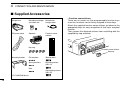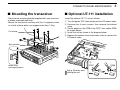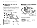
1
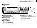
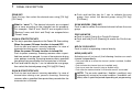
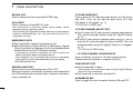
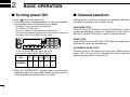
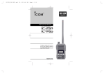
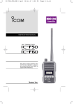
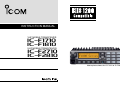
INSTRUCTION MANUAL
VHF MOBILE TRANSCEIVER
iF1710
iF1810
UHF MOBILE TRANSCEIVER
iF2710
iF2810
Above photo shows the IC-F1810 or IC-F2810.
IMPORTANT
PRECAUTION
READ ALL INSTRUCTIONS carefully and com-
RWARNING! NEVER connect the transceiver to an
AC outlet. This may pose a fire hazard or result in an electric
shock.
pletely before using the transceiver.
SAVE THIS INSTRUCTION MANUAL — This
instruction manual contains important operating instructions
for the IC-F1710, IC-F1810, IC-F2710 and IC-F2810 VHF/
UHF MOBILE TRANSCEIVERS.
EXPLICIT DEFINITIONS
WORD
DEFINITION
Personal injury, fire hazard or electric shock
RWARNING may occur.
CAUTION
NOTE
Equipment damage may occur.
If disregarded, inconvenience only. No risk
of personal injury, fire or electric shock.
NEVER connect the transceiver to a power source of more
than 16 V DC such as a 24 V battery. This connection will ruin
the transceiver.
NEVER cut the DC power cable between the DC plug and
fuse holder. If an incorrect connection is made after cutting,
the transceiver might be damaged.
NEVER place the transceiver where normal operation of
the vehicle may be hindered or where it could cause bodily
injury.
NEVER allow children to touch the transceiver.
NEVER expose the transceiver to rain, snow or any liquids.
USE the specified microphone only. Other microphones
have different pin assignments and may damage the transceiver.
Icom, Icom Inc. and the
logo are registered trademarks of Icom
Incorporated (Japan) in the United states, the United Kingdom, Germany,
France, Spain, Russia and/or other countries.
All other products or brands are registered trademarks or trademarks of their
respective holders.
i
DO NOT use or place the transceiver in areas with temperatures below –30°C or above +60°C, or in areas subject to
direct sunlight, such as the dashboard.
AVOID operating the transceiver without running the vehicle’s engine. The vehicle’s battery will quickly run out if the
transceiver transmits while the vehicle’s engine OFF.
AVOID placing the transceiver in excessively dusty environments.
AVOID
placing the transceiver against walls. This will
obstruct heat dissipation.
AVOID the use of chemical agents such as benzine or
alcohol when cleaning, as they damage the transceiver surfaces.
BE CAREFUL! The transceiver will become hot when
operating continuously for long periods.
ii
TABLE OF CONTENTS
IMPORTANT ....................................................................................... i
EXPLICIT DEFINITIONS .................................................................... i
PRECAUTION .................................................................................... i
TABLE OF CONTENTS .................................................................... iii
1 PANEL DESCRIPTION .............................................................. 1–7
■ Front panel .................................................................................. 1
■ Function display .......................................................................... 2
■ Programmable function keys ...................................................... 3
2 BASIC OPERATION ................................................................ 8–13
■ Turning power ON ....................................................................... 8
■ Channel selection ....................................................................... 8
■ Call procedure ............................................................................ 9
■ Receiving and transmitting ......................................................... 9
D Transmitting notes .................................................................. 10
D TX code channel selection ..................................................... 10
D TX code number edit .............................................................. 11
D DTMF transmission ................................................................ 12
■ Scrambler function .................................................................... 12
■ User set mode .......................................................................... 13
3 BIIS OPERATION ................................................................... 14–24
■ Default setting ........................................................................... 14
■ Receiving a call ......................................................................... 14
D Individual call.......................................................................... 14
D Group call ............................................................................... 15
D Displaying the received call record—Queue indication .......... 15
■ Transmitting a call ..................................................................... 16
D Using call memory.................................................................. 16
D Calling back from the queue channel ..................................... 16
D Direct code entry .................................................................... 17
iii
■ Receiving a message ............................................................... 18
D Receiving a status message .................................................. 18
D Receiving an SDM (Short Data Message) ............................. 18
D Received message selection.................................................. 19
■ Transmitting a status ................................................................. 20
D General................................................................................... 20
D Transmitting a status .............................................................. 20
■ Transmitting an SDM (Short Data Message) ............................. 21
D General................................................................................... 21
D Transmitting an SDM.............................................................. 21
D Programming an SDM memory.............................................. 22
■ Position data transmission ........................................................ 23
■ Printer connection ..................................................................... 23
■ Digital ANI ................................................................................. 23
■ Auto emergency transmission ................................................... 23
■ Stun function ............................................................................. 24
■ BIIS indication ........................................................................... 24
■ Priority A channel selection ....................................................... 24
■ Horn output ............................................................................... 24
4 CONNECTION AND MAINTENANCE ................................... 25–29
■ Rear panel connection .............................................................. 25
■ Supplied Accessories ................................................................ 26
■ Mounting the transceiver ........................................................... 27
■ Optional UT-111 installation ...................................................... 27
■ Optional UT-109 or UT-110 installation ..................................... 28
■ Optional OPC-617 installation ................................................... 28
■ Antenna...................................................................................... 29
■ Fuse replacement ..................................................................... 29
■ Cleaning .................................................................................... 29
■ Options ..................................................................................... 29
5 DOC .............................................................................................. 30
PANEL DESCRIPTION
1
■ Front panel
q
1
w
e*
e*
Icom
IC-F1710
F2710
Inc
IC-F1810
F2810
o
i
u y t
q AF VOLUME CONTROL KNOB
Rotate the knob to adjust the audio output level.
• Minimum audio level is pre-programmed.
w FUNCTION DISPLAY (p. 2)
Displays a variety of information, such as an operating
channel number/name, 5-tone code, DTMF numbers and
audible condition, etc.
e DIAL or UP/DOWN KEYS
• IC-F1710, F2710: DIAL
Rotate to select an operating channel, etc.
• IC-F1810, F2810: UP/DOWN Keys
Push to select an operating channel, etc.
r
r 10-KEYPAD (IC-F1810 or IC-F2810 only)
The keypad allows you to enter digits to:
• Select memory channels, tone channels and DTMF codes
(when in the DTMF code channel selection mode)
• Set TX codes and BIIS status number
• Input text message for SDM operation
• Start up with a password
t BUSY INDICATOR
Lights green while receiving a signal, or when the squelch
is open.
*The desired function can be assigned by your dealer. (p. 3)
1
1
PANEL DESCRIPTION
y POWER SWITCH [POWER]
Push to turn the power ON and OFF.
• The following functions are available at power ON as options:
- Automatic scan start
- Password prompt
- Set mode
u TRANSMIT INDICATOR
Lights red while transmitting.
i DEALER-PROGRAMMABLE KEYS
Desired functions can be programmed independently by
your dealer. (p. 3)
In this instruction manual, these keys are from the left,
called [P0]/[P1]/[P2]/[P3]/[P4].
o MICROPHONE CONNECTOR
Connect the supplied microphone or optional DTMF microphone.
NEVER connect non-specified microphones. The pin
assignments may be different and the transceiver may
be damaged.
D MICROPHONE
The supplied microphone has a PTT switch and a hanger
hook.
• The following functions are available when the microphone is on or
off hook:
- Automatic scan start when on hook.
- Automatic priority channel selection when off hook.
- Sets to ‘Inaudible’ condition (mute condition) when on hook.
- Sets to ‘Audible’ condition (unmute condition) when off hook.
2
■ Function display
q
w
e
r
136.1
t
y
u
i
o
Nar
!0
!1
q SIGNAL STRENGTH INDICATOR
Indicates relative signal strength level.
w LOW POWER INDICATOR
Appears when low output power is selected.
e AUDIBLE INDICATOR
➥ Appears when the channel is in the ‘audible’ (unmute)
condition.
➥ Appears when the specified 5-tone/BIIS code is
received.
r COMPANDER INDICATOR
Appears when the compander function is activated.
t SCRAMBLER INDICATOR
Appears when the voice scrambler function is activated.
PANEL DESCRIPTION
1
■ Programmable function keys
y BELL INDICATOR
Appears/blinks when the specific 5-tone/BIIS code is
received, according to the pre-programming.
u CALL CODE MEMORY INDICATOR
Appears when the call code memory is selected.
i SDM MEMORY INDICATOR
Appears when the SDM memory is displayed.
o SDM INDICATOR
Appears when an SDM is received, or a transmit SDM is
selected.
!0 ALPHANUMERIC DISPLAY
Displays an operating channel number, channel name, Set
mode contents, DTMF code, etc.
The indication mode can be selected from 1 line or 2 lines.
Ask your dealer for details.
In this instruction manual, the LCD illustration is described
using the 2 lines indication mode.
!1 ACTIVATED KEY INDICATOR
Appears above the key assigned as [DIGITAL] key when
that key has been activated.
1
The following functions can be assigned to [DIAL]*, [UP],
[DOWN], [P0], [P1], [P2], [P3] and [P4] programmable function keys.
Consult your Icom dealer or system operator for details concerning your transceivers programming.
If the programmable function names are bracketed in the following explanations, the specific key is used to activate the
function depends on the programming.
*The functions you can assign to [DIAL] are limited.
(Only functions marked with ✩ can be assigned.)
✩ CH UP AND DOWN KEYS
➥ Push (or Rotate)* to select an operating channel.
➥ Push (or Rotate)* to select a transmit code channel after
pushing [TX Code CH Select].
➥ Push (or Rotate)* to select a DTMF channel after pushing
[DTMF Autodial].
➥ Push (or Rotate)* to select a scan group after pushing and
holding [Scan A Start/Stop]/[Scan B Start/Stop].
➥ Push (or Rotate)* to select a BIIS code, status number or
SDM after pushing [Digital].
*Rotate when this function is assigned to [DIAL].
✩ ZONE UP AND DOWN KEY (This function is for [DIAL] only)
Rotate to select the desired zone.
3
1
PANEL DESCRIPTION
ZONE KEY
Push this key, then select the desired zone using [CH Up]/
[CH Down].
➥ Push and hold this key for 1 sec. to indicate the scan
group, then select the desired group using [CH Up]/
[CH Down].
What is “zone”?—The desired channels are assigned
into a zone according to the intended use for grouping.
For example, ‘Staff A’ and ‘Staff B’ are assigned into a
“Business” zone, and ‘John’ and ‘Cindy’ are assigned into a
“Private” zone.
SCAN ADD/DEL (TAG) KEY
Push to add or delete the selected channel to/from the scan
group.
SCAN A START/STOP KEY
➥ This key’s operation depends on the Power ON Scan setting.
When the power ON scan function is turned OFF;
Push to start and cancel scanning operation. In case of
transmission during scan, cancels scanning.
When the power ON scan function is turned ON;
Push to pause scanning. Scanning resumes after a specified time period has passed. In case of transmission during
scan, pauses scanning. Scanning resumes after a specified
time period has passed after the transmission is finished.
➥ Push and hold this key for 1 sec. to indicate the scan group,
then select the desired group using [CH Up]/[CH Down].
SCAN B START/STOP KEY
➥ Push to start and cancel scanning operation. In case of
transmission during scan, pauses scanning. Scanning
resumes after a specified time period has passed after the
transmission is finished.
4
PRIO A/B KEYS
➥ Push to select Priority A or Priority B channel.
➥ Push and hold [Prio A (Rewrite)] to rewrite the Prio A channel.
MR-CH 1/2/3/4 KEYS
Push to select an operating channel directly.
MONI (AUDI) KEY
Activates one of (or two of) the following functions on each
channel independently:
• Push and hold to un-mute the channel (audio is emitted; ‘Audible’
condition).
• Push to mute the channel (sets to ‘Inaudible’ only).
• Push to un-mute the channel (sets to ‘Audible’ only).
• Push after the communication is finished to send a ‘reset code’.
NOTE: The un-mute condition (‘Audible’ condition) may
automatically return to the mute condition (‘Inaudible‘ condition) after a specified period depending on programming.
PANEL DESCRIPTION
PUBLIC ADDRESS KEY
While in the hailer mode, push this key for the audio output
via the hailer amplifier. Ask your dealer for details.
While in the normal mode, the audio output via the cable can
be controlled from the transceiver separately from [VOL] control knob when an optional OPC-617 ACC CABLE is installed.
• This audio output can be used as a ‘public address’ function when
an external audio amplifier and speaker are connected additionally.
• Push this key, then speak into the microphone while pushing the
PTT switch.
• [CH Up]/[CH Down] allow you to set the audio output level from minimum to maximum.
RX SPEAKER KEY
While in the hailer mode, the external speaker drive function
is also available simultaneously when the external connections are made for the ‘public address’ function. The received
audio can be heard via the external speaker when this key is
pushed.
• This function is useful when you are out of the vehicle.
• The audio output level is linked to the transceiver’s volume control.
LIGHT KEY
Push to turn the transceiver’s backlight ON for about 5 sec.
when the backlight function is turned OFF in user set mode.
LOCK KEY
Push and hold to electronically lock all programmable keys
except the following:
[Call] (incl. Call A and Call B), [Moni(Audi)] and [Emergency].
1
HIGH/LOW KEY
Push to select the transmit output power temporarily or permanently, depending on the pre-setting.
1
• Ask your dealer for the output power level for each selection.
C.TONE CH ENT KEY
Push to select the continuous tone channel using [CH Up]/
[CH Down] to change the tone frequency/code setting after
pushing this key. The selected channel remains set as the
continuous tone channel until another channel is designated
as such.
TALK AROUND KEY
Turn the talk around function ON and OFF.
• The talk around function equalizes the transmit frequency to the
receive frequency for transceiver-to-transceiver communication.
WIDE/NARROW KEY
Push to toggle the IF bandwidth between wide and narrow.
• The wide passband width can be selected from 25.0 or 20.0 kHz
using the CS-F70/F1700 CLONING SOFTWARE. Ask your Dealer for
details.
DTMF AUTODIAL KEY
➥ Push to enter the DTMF channel selection mode. Then
select the desired DTMF channel using [CH Up]/[CH Down].
➥ After selecting the desired DTMF channel, push this key to
transmit the DTMF code.
5
1
PANEL DESCRIPTION
RE-DIAL KEY
Push to transmit the last-transmitted DTMF code.
CALL KEYS
Push to transmit a 5-tone/BIIS ID code.
• Call transmission is necessary before calling another station
depending on your signalling system.
• [Call A] and/or [Call B] may be available when your system employs
selective ‘Individual/Group’ calls. Ask your dealer which call is
assigned to each key.
EMERGENCY KEYS
➥ Push and hold to transmit an emergency call.
➥ When [Emergency Single (Silent)] or [Emergency Repeat
(Silent)] is pushed, an emergency call is transmitted without
a beep emission and LCD indication change.*
• If you want to cancel the emergency call, push (or push and
hold) the key again before transmitting the call.
• The emergency call is transmitted one time only or repeatedly
until receiving a control code depending on the pre-setting.
*BIIS PMR operation only
SURVEILLANCE KEY
Push to turn the surveillance function ON or OFF.
When this function is turned ON, the beep is not emitted and
the LCD backlight does not light when a signal is received or
a key is pushed, etc.
6
TX CODE ENTER KEY
Push to enter the ID code edit mode directly, for both 5-tone
and BIIS. Then set the desired digit using [CH Up]/
[CH Down] or 10-keypad*. (p. 11)
*IC-F1810 or IC-F2810 only
TX CODE CHANNEL SELECT KEY
➥ Push to enter the ID code channel selection mode directly.
Then set the desired channel using [CH Up]/[CH Down].
(p. 10)
➥ During ID code channel selection mode, push for 1 sec. to
enter the ID code edit mode for 5-tone and BIIS. Then set
the desired digit using [CH Up]/[CH Down] or 10-keypad*.
(p. 11)
*IC-F1810 or IC-F2810 only
✩ TX CODE CHANNEL UP/DOWN KEYS
Push (or Rotate)* to select a TX code channel directly.
*Rotate when this function is assigned to [DIAL].
ID-MR SELECT KEY
➥ Recalls detected ID codes.
• Push this key, then select the ID code using [CH Up]/[CH Down].
• Up to 5 ID’s are memorized.
➥ Push and hold to erase the selected ID’s.
SCRAMBLER KEY
Push to toggle the voice scrambler function ON and OFF.
PANEL DESCRIPTION
COMPANDER KEY
Push to toggle the compander function ON and OFF.
The compander function reduces noise components from the
transmitted audio to provide clear communication.
HOOK SCAN KEY
When the hook on scan function is turned ON, push this key
to stop scanning temporarily. Push this key again to re-start
scanning.
1
✩ STATUS UP/DOWN KEYS (BIIS operation only)
➥ While in the standby condition, push (or rotate)* to display
the transmit status indication and select a status number.
➥ When a received SDM is displayed, push (or rotate)* to
cancel the automatic scroll and scroll the message manually.
➥ When an SDM that contains more than 12 characters is
displayed, push (or rotate)* to scroll the message manually.
1
*Rotate when this function is assigned to [DIAL].
USER SET MODE KEY
➥ Push and hold to enter user set mode.
• During user set mode, push this key to select an item, and
change the value or condition using push [CH Up]/[CH Down].
➥ Push and hold this key again to exit user set mode.
User set mode is also available via the ‘Power ON function.’
Refer to p. 13 also.
OPT 1/2/3 KEYS
Push to control the output signal level of the optional ports in
the optional unit connector.
DIGITAL BUTTON KEY (BIIS operation only)
➥ Push to select the call ID list, transmit message and standby condition. Toggles between queue channel and
received message record indication after queue channel is
selected.
➥ Push and hold to select queue channel indication.
7
2
BASIC OPERATION
■ Turning power ON
■ Channel selection
q Push [ ] to turn the power ON.
w If the transceiver is programmed for a start up password,
input the digit codes as directed by your dealer.
Several types of channel selections are available. Methods
may differ according to your system set up.
• 10-keypad* can be used for password input.
*IC-F1810 or IC-F2810 only
• The keys as below can be used for password input:
The transceiver detects numbers in the same block as identical.
Therefore “01234” and “56789” are the same.
NON-ZONE TYPE:
Push [CH Up] or [CH Down], or rotate [CH Up/Down] to select
the desired operating channel, in sequence; or, push one of
[MR-CH 1] to [MR-CH 4] keys to select a channel directly.
ZONE TYPE:
Push [Zone] then push [CH Up] or [CH Down], or rotate [Zone
Up/Down] to select the desired zone.
P0
P1
P2
P3
P4
In this instruction manual, these keys are
from the left, called [P0]/[P1]/[P2]/[P3]/[P4].
KEY
NUMBER
P0
P1
P2
P3
P4
0
1
2
3
4
5
6
7
8
9
e When the “PASSWORD” indication does not clear after
inputting 6 digits, the input code number may be incorrect.
Turn the power off and start over in this case.
8
AUTOMATIC SCAN TYPE:
Channel setting is not necessary for this type. When turning
power ON, the transceiver automatically starts scanning.
Scanning stops when receiving a call.
BASIC OPERATION
2
■ Call procedure
■ Receiving and transmitting
When your system employs tone signaling (excluding CTCSS
and DTCS), the call procedure may be necessary prior to voice
transmission. The tone signalling employed may be a selective calling system which allows you to call specific station(s)
only and prevent unwanted stations from contacting you.
Receiving:
q Push [ ] to turn the power ON.
w Push [CH Up] or [CH Down], or rotate [CH Up/Down] to
select a channel, in sequence.
e When receiving a call, adjust the audio output level to a
comfortable listening level.
q Select the desired TX code channel or 5-tone code
according to your System Operator’s instructions.
• This may not be necessary depending on programming.
• Refer to pgs. 10–11 for selection.
w Push the call key (assigned to one of the dealer programmable keys) or [PTT].
e After transmitting, the remainder of your communication
can be carried out in the normal fashion.
Selective calling
Non-selective calling
2
Transmitting:
Wait for the channel to become clear to avoid interference.
q Take the microphone off hook.
• 5-tone mute may be released. (The ‘audible’ condition is selected and BUSY indicator lights green.)
• A priority channel may be selected automatically.
w Wait for the channel to become clear.
• The channel is busy when BUSY indicator lights green.
e Push [CALL] when initiating a call from your side.
• Coded audio may be heard from the transceiver, then “
”
appears.
• This operation may not be necessary depending on your signaling system. Ask your dealer for details.
r While pushing and holding [PTT], speak into the microphone at your normal voice level.
t Release [PTT] to receive.
IMPORTANT: To maximize the readability of your signal;
1. Pause briefly after pushing [PTT].
2. Hold the microphone 5 to 10 cm from your mouth, then
speak into the microphone at a normal voice level.
9
2
BASIC OPERATION
D Transmitting notes
D TX code channel selection
• Transmit inhibit function
The transceiver has several inhibit functions which restrict
transmission under the following conditions:
- The channel is in mute condition (‘Inaudible’ condition;
“
” does not appear.)
- The channel is busy.
- Un-matched (or matched) CTCSS is received.
(Depending on the pre-setting.)
- The selected channel is a ‘receive only’ channel.
• Time-out timer
After continuous transmission for the pre-programmed time
period, the time-out timer is activated, causing the transceiver to stop transmitting.
• Penalty timer
Once the time-out timer is activated, transmission is further
inhibited for a period determined by the penalty timer.
If the transceiver has [TX Code CH Select] assigned to it, the
indication can be toggled between the operating channel
number (or name) and TX code channel number (or name).
When the TX code channel number (or name) is displayed,
[CH Up]/[CH Down] selects the TX code channel.
USING [TX CODE CH SELECT] KEY:
q Push [TX Code CH Select]— a TX code channel number
(or name) appears.
w Push [CH Up] or [CH Down], or rotate [CH Up/Down] to
select the desired TX code channel.
e Push [Call] (or [PTT] during BIIS operation) to transmit the
selected TX code.
USING [TX CODE CH UP]/[TX CODE CH DOWN] KEY:
If the transceiver has a [TX Code CH Up], [TX Code CH
Down] or [TX Code CH Up/Down] key assignment, the programmed TX code channel can be selected directly when
pushed or rotated.
NOTE for PMR or BIIS PMR operation:
• The LCD indication does not change when the operating
channel number (or name) is displayed. (Depending on
the pre-setting)
• To check the selected TX code, push [TX Code CH
Select].
10
BASIC OPERATION
D TX code number edit
If the transceiver has [TX Code CH Select] or [TX Code
Enter] assigned to it, TX code contents can be edited within
the allowable digits.
USING [TX CODE CH SELECT] KEY:
q Push [TX Code CH Select] to enter the TX code channel
selection mode.
• Select the desired channel before entering the TX code channel
selection mode if necessary.
w Push [TX Code CH Select] for 1 sec. to enter the TX code
edit mode.
e Push [TX Code CH Select] to select the desired digit to be
edited.
• The digit to be edited blinks.
r Push [CH Up], [CH Down] or 10-keypad*, or rotate [CH
Up/Down] to set the desired digit.
t Push [TX Code CH Select] to set the digit. The digit to the
right will blink automatically.
2
USING [TX CODE ENTER] KEY:
q Select the desired TX code channel via [TX Code CH
Select]+[CH Up] or [CH Down], [TX Code CH Up], [TX
Code CH Down] or [TX Code CH Up/Down].
w Push [TX Code Enter] to enter the TX code edit mode.
e Push [TX Code Enter] to select the desired digit to be edited.
2
• The digit to be edited blinks.
r Push [CH Up], [CH Down] or 10-keypad*, or rotate [CH
Up/Down] to set the desired digit.
t Push [TX Code Enter] to set the digit. The digit to the right
will blink automatically.
• When the 10-keypad* is used for setting, the digit to the right will
blink automatically without pushing [TX Code CH Select].
y Repeat r and t to input all allowable digits.
u Push [Call] or [PTT] to transmit the edited TX code.
*IC-F1810 or IC-F2810 only
• When the 10-keypad* is used for setting, the digit to the right will
blink automatically without pushing [TX Code CH Select].
y Repeat r and t to input all allowable digits.
u Push [Call] or [PTT] to transmit the edited TX code.
*IC-F1810 or IC-F2810 only
11
2
BASIC OPERATION
D DTMF transmission
If the transceiver has [DTMF Autodial] assigned to it, the automatic DTMF transmission function is available. Up to 8 DTMF
channels are available.
TO SELECT A TX CODE:
q Push [DTMF Autodial]— a DTMF channel appears.
w Push [CH Up] or [CH Down], or rotate [CH Up/Down] to
select the desired DTMF channel.
e Push [DTMF Autodial] to transmit the DTMF code in the
selected DTMF channel.
■ Scrambler function
The voice scrambler function provides private communication
between stations. The frequency inversion type is equipped
to all versions, moreover, the optional Rolling or Non-rolling
type can be available.
q Push [Scrambler] to turn the scrambler function ON.
•“
•“
12
” appears.
w Push [Scrambler] again to turn the scrambler function
OFF.
” disappears.
BASIC OPERATION
2
■ User set mode
User set mode is accessed with [User Set Mode] and allows
you to set seldom-changed settings. In this case you can
“customize” the transceiver operation to suit your preferences
and operating style.
Entering the user set mode:
q While pushing and holding [P1] and [P2], push [ ] to turn
the power ON. Then, push and hold [P0] to enter user set
mode.
[P0] [P1] [P2]
[
e Push [
] again to exit set mode.
[
2
]
User set mode is also available via a programmable key.
Please refer to p. 7 [User Set Mode] section.
]
w Push [P0] several times to select the appropriate item.
Then, push [Up] or [Down] or rotate [DIAL] to set the
desired level/condition.
• Available set mode functions are Backlight, LCD Contrast,
Beep, Beep Level, SQL Level, AF Min Level, Mic Gain, Horn
and Signal Moni.
[P0]
[Up]/[Down] or [DIAL]
13
3
BIIS OPERATION
■ Default setting
■ Receiving a call
The following functions are assigned to each programmable
key as the default. However, the assigned function can be
changed by your dealer. Ask your dealer for details.
NOTE: [TX Code Enter] must be assigned to a key.
P0
[P0]; Call
P1
P2
P3
P4
In this instruction
manual, these keys
are from the left,
called [P0]/[P1]/
[P2]/[P3]/[P4].
: Push to transmit a 5-tone/BIIS call
when the selected channel is a 5tone or BIIS channel.
[P1]; Digital
: Push to select the call list ID/transmit
message, or to display the receive
message record for selection.
[P3]; TX Code Enter : Push to enter the ID code edit mode
directly for both 5-tone and BIIS.
[P4]; Moni(Audi)
: Push this key after the communication to send a ‘Clear down’ signal
during BIIS channel operation.
[P2]; Null
: No function is assigned.
[Up]/[Down]/[DIAL]; CH Up/Down
: While in the standby condition,
selects the operating channel.
After pushing [Digital] or [TX Code
CH Select], selects call list or TX
code channel, respectively.
14
D Individual call
q When an individual call is received;
• Beeps sound.
•“
” appears and the mute is released.
• The programmed text message (e.g.“CALLING”) and the calling
station ID (or text) is displayed when the indication mode is 2
lines.
• The programmed text message (e.g.“CALLING”) and the calling
station ID (or text) is displayed alternately when the indication
mode is 1 line, depending on the setting.
• “ ” appears or blinks depending on the setting.
Appears
Appears or blinks
CALLING
0500
w Push and hold [PTT], then speak into the microphone at a
normal voice level.
• TX indicator lights red.
e Release [PTT] to return to receive.
• BUSY indicator lights green while receiving a signal.
r To finish the conversation, push [P4] (Moni(Audi)) to send
the ‘Clear down’ signal.
• Either station can send a ‘Clear down’ signal.
• “CLR DOWN” is displayed for 2 sec. (approx.).
•“
” disappears and the transceiver returns to the standby condition.
BIIS OPERATION
D Group call
D Displaying the received call record
— Queue indication
q When a group call is received;
• Beeps sound.
•“
” appears and the mute is released.
• The programmed text message (e.g.“GROUP”) and the calling station ID (or text) is displayed when the indication mode is 2 lines.
• The programmed text message (e.g.“GROUP”) and the calling
station ID (or text) is displayed alternately when the indication
mode is 1 line, depending on the setting.
• “ ” appears or blinks depending on the setting.
Appears
3
Appears or blinks
GROUP
1120
w Push and hold [PTT], then speak into the microphone at a
normal voice level.
• TX indicator lights red.
NOTE: Only one station is permitted to speak.
e Release [PTT] to return to receive.
• BUSY indicator lights green while receiving a signal.
r To finish the conversation, push [P4] (Moni(Audi)) to send
the ‘Clear down’ signal.
• Either station can send a ‘Clear down’ signal.
• “CLR DOWN” is displayed for 2 sec. (approx.)
•“
” disappears and the transceiver returns to the standby condition.
3
The transceiver memorizes the calling station ID in the memory. Up to 3 calls can be memorized, and the oldest call
record is erased when a 4th call is received. However, once
the transceiver is powered OFF, the all records are cleared.
q Push [P1] (Digital) for 1 sec.
• Displays following indication.
When a record is available
<QUEUE>
-QUEUE!When no record is available
<QUEUE>
NO QUEUE
w Push [Up] or [Down], or rotate [DIAL] to select the desired
call.
e Push [P1] (Digital) for 1 sec. again to return to the standby
condition.
• When no operation is performed for 30 sec., the transceiver
returns to the standby condition automatically.
15
3
BIIS OPERATION
■ Transmitting a call
A total of 3 ways for code selection are available—selecting
the call code from memory, entering the call code from the
keypad and calling back from the queue channel record.
D Using call memory
q While in the standby condition, push [P1] (Digital) to enter
the call code memory channel selection mode.
•“
” appears.
D Calling back from the queue channel
q While in the standby condition, push [P1] (Digital) for
1 sec. to enter the queue memory channel selection mode.
w Push [Up] or [Down] or rotate [DIAL] to select the desired
record.
<QUEUE>
-QUEUE!-
Appears
e Push [P0] (Call) or [PTT]* to call.
CALLING
0500
w Push [Up] or [Down], or rotate [DIAL] to select the desired
call code.
e Push [P0] (Call) or [PTT]* to call.
*PTT call can be made only when PTT call capability is permitted.
NOTE: When no answer back is received, the transceiver repeats the call 3 times (default) automatically,
and “WAIT” is displayed during each call. However, an
error beep sounds and “FAILED” is displayed when no
answer back is received after the calls.
r Push [PTT] to transmit; release to receive.
t Push [P4] (Moni(Audi)) to send the ‘Clear down’ signal.
16
*PTT call can be made only when PTT call capability is permitted.
NOTE: When no answer back is received, the transceiver repeats the call 3 times (default) automatically,
and “WAIT” is displayed during each call. However, an
error beep sounds and “FAILED” is displayed when no
answer back is received after the calls.
r Push [PTT] to transmit; release to receive.
t Push [P4] (Moni(Audi)) to send the ‘Clear down’ signal.
BIIS OPERATION
3
D Direct code entry
q While in the standby condition, push [P3] (TX Code Enter)
to enter the TX code edit mode.
u Push [PTT] to transmit; release to receive.
i Push [P4] (Moni(Audi)) to send the ‘Clear down’ signal.
3
• Code digit for editing blinks.
0500
For your information
When the “UpDate” setting for the call code is enabled, the
set code is overwritten into the call code memory.
w Push [P3] (TX Code Enter) to select the desired digit to be
edited.
• Digit for editing differs according to the setting.
e Set the desired digit using [CH Up]/[CH Down]/[DIAL] or
10-keypad*.
*IC-F1810 or IC-F2810 only
r Push [P3] (TX Code Enter) to set the digit, then the digit
to the right will blink automatically.
• When the 10-keypad is used for setting, the digit to the right will
blink automatically without pushing [P3] (TX Code Enter).
t Repeat e and r to input all allowable digits.
y Push [P0] (Call) or [PTT]* to call.
*PTT call can be made only when PTT call capability is permitted.
NOTE: When no answer back is received, the transceiver repeats the call 3 times (default) automatically,
and “WAIT” is displayed during each call. However, an
error beep sounds and “FAILED” is displayed when no
answer back is received after the calls.
17
3
BIIS OPERATION
■ Receiving a message
D Receiving a status message
D Receiving an SDM (Short Data Message)
q When a status message is received;
q When an SDM is received;
• Beeps sound.
• The calling station ID (or text) and the status message is displayed alternately when the indication mode is 1 line, depending
on the setting.
RX Status
BASE
• Beeps sound.
• The calling station ID (or text) and the SDM is displayed alternately when the indication mode is 1 line, depending on the setting.
•“
” appears.
01
w Push [P4] (Moni(Audi)) to return to the standby condition.
NOTE: Only the calling station ID (or text) is displayed (no
message is displayed alternately) when the scroll timer is
set to ‘OFF.’ In this case, push [Status Up]/[Status Down]
to display the status message manually.
Appears
SDM 8
BASE
w When the received SDM includes more than 12 characters, the message scrolls automatically, when the automatic scroll function is activated.
• Push [Status Up]/[Status Down] to scroll the message manually.
SDM 12345678
BASE
e Push [P4] (Moni(Audi)) to return to the standby condition.
18
BIIS OPERATION
3
D Received message selection
The transceiver memorizes the received message in the
memory. Up to 6 messages for status and SDM, or 95 character SDM’s can be memorized. The oldest message is
erased when the 7th message is received. However, once the
transceiver is powered OFF, all messages are cleared.
r Push [P1] (Digital) for 1 sec. again to return to the standby
condition.
3
• When no operation is performed for 30 sec., the transceiver
returns to the standby condition automatically.
q Push [P1] (Digital) for 1 sec.
• Displays queue memory.
w Push [P1] (Digital) momentarily.
• Displays message memory.
When a message is available
MESSAGE
- MSG! When no message is available
MESSAGE
-NO MSGe Push [Up] or [Down], or rotate [DIAL] to select the desired
message.
• When selecting the SDM that includes more than 12 characters,
the message scrolls automatically when the automatic scroll
function is activated.
• Push [Status Up]/[Status Down] to scroll the message manually.
19
3
BIIS OPERATION
■ Transmitting a status
D General
D Transmitting a status
The status message can be selected with the programmed
text, and the message text is also displayed on the function
display of the called station.
Up to 24 status types (1 to 24) are available, and the status
messages 22 and 24 have designated meanings.
Status 22: Emergency*
Status 24: GPS request
q While in the standby condition, push [P1] (Digital), then
push [Up] or [Down], or rotate [DIAL] to select the desired
station/group code.
w Push [P1] (Digital) again, then push [UP] or [DOWN] to
select the desired status message.
*The status 22 can also be used as a normal status message by
disabling the designated meaning. However, the status 24 is fixed.
The status call can be sent with both individual and group
calls.
Or, you can select the desired status message using
[Status Up]/[Status Down] key directly.
STATUS 01
TX Status 01
Status message is displayed.
e Push [P0] (Call) or [PTT]* to transmit the status message
to the selected station/group.
*PTT call can be made only when PTT call capability is permitted.
• 2 beeps will sound and the transceiver returns to the standby
condition automatically when the transmission is successful.
20
BIIS OPERATION
3
■ Transmitting an SDM (Short Data Message)
D General
D Transmitting an SDM
The short data message, SDM, can be sent to an individual
station or group stations. Also, 8 SDM memory channels are
available and the messages can be edited via PC programming.
q While in the standby condition, push [P1] (Digital), then
push [Up] or [Down] or rotate [DIAL] to select the desired
station/group code.
w Push [P1] (Digital) again, then push [Up] or [Down] or
rotate [DIAL] to select the desired SDM.
3
Or, you can select the desired SDM using [Status Up]/
[Status Down] key directly.
Appears
MESSAGE
SDM 1
1
SDM is displayed.
e Push [P0] (Call) or [PTT]* to transmit the SDM to the
selected station/group.
*PTT call can be made only when PTT call capability is permitted.
• 2 beeps will sound and the transceiver returns to the standby
condition automatically when the transmission is successful.
21
3
BIIS OPERATION
D Programming an SDM memory
• Available characters
(IC-F1810 or IC-F2810 only)
Key
q During standby condition, push [P1] (Digital) twice, then
push [Up] or [Down] to select the desired SDM to be edited.
w Push [M] or [#] to enter the message editing condition.
• The first character blinks when [#] is pushed, the last character
blinks when [M] is pushed.
•“
” blinks.
Blinks
Blinks
MESSAGE
SDM 8
8
When [#] is pushed.
e Push the appropriate digit key, [0] to [9], to enter the
desired character.
• See the table at right for the available characters.
• Pushing [UP] also enters space, pushing [DOWN] deletes the
selected character.
r Push [#] to move the cursor to the right, push [M] to move
the cursor to the left.
t Repeat steps e and r to set the desired text message.
y Push [P1] (Digital) for 1 sec. to overwrite the set content
into the memory.
• Push [P1] (Digital) momentarily to cancel the editing and return to
the original message indication.
22
[0]
[1]
[2]
[3]
[4]
[5]
[6]
[7]
[8]
[9]
Characters
0
1
2
3
4
5
6
7
8
9
!! ? ' " , ; : _ ( ) < > [ ]
(space) # * / + - = / & % $ @ ^
A B C a b c
D E F d e f
G H I g h i
J K L j k l
M N O m n o
P Q R S p q r s
T U V t u v
W X Y Z w x y z
NOTE: A decimal point can only be written with the CSF70/F1700 CLONING SOFTWARE. Pre-programmed characters can be rewritten with the 10-keypad, except for the
decimal point, as it is not included in the transceiver character list, and cannot be displayed again.
BIIS OPERATION
3
■ Position data transmission
■ Digital ANI
When the optional cable and a GPS receiver is connected to
the transceiver, the position (longitude and latitude) data can
be transmitted automatically.
Ask your dealer or system operator for connection details.
The own ID can be transmitted each time the PTT is pushed
(log-in) or released (log-off) during individual or group call
communications.
By receiving the ANI, the communication log can be recorded
when using a PC dispatch application.
The position data is transmitted when;
• Status 24 message is received
*When the status 24 message, GPS request, is received.
• Fully automatic
When automatic position transmission is enabled, send
the position data according to ‘Time Marker’ and ‘Interval
Timer’ settings.
• PTT is released
When ‘Send with Logoff’ is enabled.
- Set the ‘Log-In/Off’ item as ‘L-OFF.’
• After sending a status message
When ‘Send with Status’ is enabled.
• After sending an SDM
When ‘Send with SDM’ is enabled.
• After sending status 22 (Emergency)
When ‘Send with Emergency’ is enabled.
■ Printer connection
When the optional cable is connected to the transceiver, a
printer can be connected to print out the received SDM content and the ID of the station who sent the message.
Ask your dealer or system operator for connection details.
3
In addition, when using the ANI with log-in, the PTT side tone
function can be used to inform you that the ID is sent and
voice communication can be performed.
■ Auto emergency transmission
When [Emergency Single (Silent)] or [Emergency Repeat
(Silent)] is pushed, an emergency signal is automatically
transmitted for the specified time period.
The status 22 (Emergency) is sent to the selected ID station,
and the position data is transmitted after the emergency signal when a GPS receiver is connected to the transceiver.
The emergency transmission is performed on the emergency
channel, however, when no emergency channel is specified,
the signal is transmitted on the previously selected channel.
There is no change in the function display or beep emission
during automatic emergency transmission.
23
3
BIIS OPERATION
■ Stun function
■ Priority A channel selection
When the specified ID, set as a killer ID, is received, the stun
function is activated.
When one of the following operations is performed, the transceiver selects the Priority A channel automatically.
When the killer ID is received, the transceiver switches to the
password required condition. Entering of the password via the
keypad is necessary to operate the transceiver again in this
case.
Priority A is selected when;
• Clear down signal is received/transmitted
- Set the ‘Move to PrioA CH’ item as ‘Clear down.’
• Turning the power ON
The Priority A channel is selected each time the transceiver power is turned ON.
• Status call
The Priority A channel is selected when transmitting a status call.
- Enable the ‘Send Status on PrioA CH’ item in the BIIS
configuration.
■ BIIS indication
The following indications are available for the BIIS operation
on a BIIS channel.
CONNECT : Individual/group call is successful.
OK
: Message (status or SDM) transmission is successful.
FAILED : No answer back is received.
WAIT
: Appears during retry of the call (2nd call).
CLR DOWN : End the communication.
BUSY
: Operating channel is in the busy condition.
■ Horn output
Automatic honking function is available when the optional
OPC-617 ACC CABLE is connected. When a status message
is received, the transceiver controls the vehicles horn for the
specified time period to inform a status message is received.
This function is convenient when the operator away from the
transceiver.
Ask your dealer or system operator, or refer to the service
manual for connection and setting details.
24
CONNECTION AND MAINTENANCE
4
■ Rear panel connection
q ANTENNA CONNECTOR
Connects to an antenna.
Contact your dealer about
antenna selection and
placement.
Antenna
w Reserved for a
future function.
e EXTERNAL
SPEAKER JACK
Connect a 4–8 Ω
external speaker.
w
q
Supplied speaker SP-22
(IC-F1810 or IC-F2810 only.
IC-F1710 and IC-F2710 has a
built-in speaker.)
e
3
4
r
y DC POWER RECEPTACLE
Connects to a 12 V DC battery. Pay attention to polarities. NEVER connect to a 24 V
battery. This could damage the transceiver.
y
Red
t
Black
12V
Battery
R CAUTION! NEVER remove
the fuse-holder from the DC
power cable.
NOTE: Use the terminals as shown
below for the cable connections.
Crimp
Solder
r MICROPHONE HANGER
Connect the supplied microphone hanger to the
vehicle’s ground for microphone on/off hook
functions. (See p. 2)
t OPTIONAL CABLE
(OPC-617)
Connect an external modem unit, dimmer control,
etc.
25
4
CONNECTION AND MAINTENANCE
■ Supplied Accessories
Microphone
Microphone hanger
and screw set
Microphone
hanger cable
DC power cable
Speaker*
Function name
stickers
• Function name stickers
There are no names on the programmable function keys
since the functions can be freely assigned to these keys.
Attach the supplied function name stickers as below to the
appropriate keys for easy recognition of that key’s assigned
function.
Then, protect the attached stickers from unsticking with the
supplied key cap as below.
KEY-STICKER
Key cap
Function name sticker
Key cap
Mounting bracket
Flat washers
Bracket bolts
Spring washers
Mounting screws
(M5×12)
Nuts
*IC-F1810/F2810 only
26
Self-tapping screws
(M5×16)
CONNECTION AND MAINTENANCE
■ Mounting the transceiver
■ Optional UT-111 installation
The universal mounting bracket supplied with your transceiver allows overhead mounting.
• Mount the transceiver securely with the 4 supplied screws
to a thick surface which can support more than 1.5 kg.
Install the optional UT-111 unit as follows:
Flat washer
4
q Turn the power OFF, then disconnect the DC power cable.
w Unscrew the 4 cover screws, then remove the bottom
cover.
e Cut the pattern on the PCB at the CP57, then solder CP58
as shown below.
r Install the unit as shown in the diagram below.
t Replace the bottom cover and screws, then re-connect the
DC power cable.
4
r
Spring washer
e
When using
self-tapping screws
CP57
CP58
See p. 28 when uninstalling the unit.
27
4
CONNECTION AND MAINTENANCE
■ Optional UT-109 or UT-110
installation
■ Optional OPC-617 installation
Install the OPC-617 as shown below.
q Turn the power OFF, then disconnect the DC power cable.
w Unscrew the 4 cover screws, then remove the bottom cover.
e Cut the pattern on the PCB at the TX mic circuit (MIC) and
RX AF circuit (AF OUT), then solder CP37 as shown below.
r Install the scrambler unit as described in the installation of
optional UT-111 installation on p. 27
t Replace the bottom cover and screws.
MIC and AF OUT
FRONT
OPC-617
Cut off the bushing as in the
illustration, when you install
the optional OPC-617.
CP37
OPTIONAL CABLE PIN ASSIGNMENT
NOTE: When uninstalling
the unit
Be sure to re-solder the
disconnected points and
un-solder the connected
points as above when you
remove the unit. Otherwise
no TX modulation or AF
output is available.
28
trewq
Re-solder
oiuy
Un-solder
Remove
q Dimmer cont. IN
w AF OUT
e Det. AF OUT
r Mod. IN
t PTT control IN or
FTSW control IN
y Horn drive cont. OUT
u AF GND
i Det. AF GND
o Mod. GND
CONNECTION AND MAINTENANCE
4
■ Antenna
■ Options
A key element in the performance of any communication system is an antenna. Contact your dealer about antennas and
the best places to mount them.
• RMK-2 SEPARATION KIT + OPC-609 SEPARATION CABLE
Allows you to install the transceiver main unit separately
from the front panel for operating convenience.
• SP-5/SP-22 EXTERNAL SPEAKER
Input impedance : 4 Ω
Max. input power : 5 W
SP-5 : Large speaker for good audio quality.
SP-22 : Compact and easy-to-install. The same as supplied
with the transceiver (depending on version.)
• HM-152/HM-152T/HM-148 HAND MICROPHONE
HM-152 : Hand microphone
HM-152T : DTMF microphone
HM-148 : Heavy duty microphone
• SM-25 DESKTOP MICROPHONE
• UT-109 (#02)/UT-110 (#02) SCRAMBLER UNITS
Non-rolling type (UT-109)/Rolling type (UT-110) voice
scrambler unit provides higher communication security.
• UT-111 LTR TRUNKING BOARD
Provides trunking operation.
• OPC-617 ACC CABLE
Allows you to connect to an external terminal.
■ Fuse replacement
A fuse is installed in the supplied DC power cable. If a fuse
blows or the transceiver stops functioning, track down the
source of the problem if possible, and replace the damaged
fuse with a new rated one.
❑ Fuse rating: 10 A
USE the 10 A fuse only.
■ Cleaning
4
If the transceiver becomes dusty or dirty, wipe it clean with a
soft, dry cloth.
AVOID the use of solvents such as benzene or
alcohol, as they may damage the transceiver surfaces.
29
5
DOC
DECLARATION
OF CONFORMITY
We Icom Inc. Japan
0168
1-1-32, Kamiminami, Hirano-ku
Osaka 547-0003, Japan
Declare on our sole responsibility that this equipment complies with the
essential requirements of the Radio and Telecommunications Terminal
Equipment Directive, 1999/5/EC, and that any applicable Essential Test
Suite measurements have been performed.
Kind of equipment:
VHF TRANSCEIVER
Type-designation:
iC-f1710/f1810
Version (where applicable):
136–174 MHz 12.5 KHz/ 25 KHz
136–174 MHz 12.5 KHz/ 20 KHz
Düsseldorf 15th Mar. 2005
Place and date of issue
Authorized representative name
This compliance is based on conformity with the following harmonised
standards, specifications or documents:
i) EN 301 489-1 v1.2.1 (2000-8)
ii) EN 301 489-5 v1.2.1 (2000-8)
iii) EN 60950 2000
iv) EN 300 086-2 v1.1.1 (March 2001)
v) EN 300 219 (March 2001)
vi) EN 300 113-2 v1.1.1 (March 2001)
CE Versions of the IC-F1710/F1810/F2710/
F2810 which display the “CE” symbol on the
serial number seal, comply with the essential
requirements of the European Radio and
Telecommunication
Terminal
Directive
1999/5/EC.
30
Signature
This warning symbol indicates that this equipment
operates in non-harmonised frequency bands
and/or may be subject to licensing conditions in the
country of use. Be sure to check that you have the
correct version of this radio or the correct programming of this radio, to comply with national
licensing requirement.
DECLARATION
OF CONFORMITY
We Icom Inc. Japan
1-1-32, Kamiminami, Hirano-ku
Osaka 547-0003, Japan
Declare on our sole responsibility that this equipment complies with the
essential requirements of the Radio and Telecommunications Terminal
Equipment Directive, 1999/5/EC, and that any applicable Essential Test
Suite measurements have been performed.
Kind of equipment:
UHF TRANSCEIVER
Type-designation:
iC-f2710/f2810
Version (where applicable):
400–470 MHz 12.5 KHz/ 25 KHz
400–470 MHz 12.5 KHz/ 20 KHz
0168
Düsseldorf 25th Feb. 2005
Place and date of issue
Authorized representative name
This compliance is based on conformity with the following harmonised
standards, specifications or documents:
i) EN 301 489-1 v1.2.1 (2000-8)
ii) EN 301 489-5 v1.2.1 (2000-8)
iii) EN 60950 2000
iv) EN 300 086-2 v1.1.1 (March 2001)
v) EN 300 219 (March 2001)
vi) EN 300 113-2 v1.1.1 (March 2001)
About e-marking: Detailed installation notes for Icom
mobile transceivers to be fitted into vehicles are available.
Please contact your Icom dealer or distributor.
Signature
5
< Intended Country of Use >
GER
AUT
GBR
IRL
NOR
A-6407H-1EU-w
Printed in Japan
© 2004–2006 Icom Inc.
Printed on recycled paper with soy ink.
FRA
NED
BEL
LUX
ESP
POR
ITA
GRE
SWE
DEN
FIN
SUI
1-1-32 Kamiminami, Hirano-ku, Osaka 547-0003, Japan