1
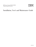
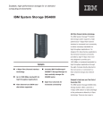
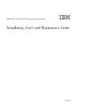
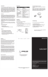
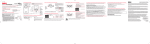
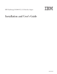
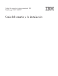
IBM TotalStorage DS4500 Storage Subsystem Fibre Channel Cabling Guide Attention This document contains important changes to the required cabling scheme for connecting storage expansion enclosures to the IBM® TotalStorage® DS4500 Storage Subsystem. The fibre channel cabling instructions in “Drive-side fibre-channel cabling” on page 4 of this document replace the information provided in the IBM TotalStorage DS4500 Fibre Channel Cabling Instructions (pn 25R0406) and the IBM TotalStorage DS4500 Installation and Support Guide (pn 25R0402). Additionally, if you are connecting DS4000 EXP700 or EXP710 storage expansion enclosures to a DS4500, follow the instructions provided in the this document and not the instructions on drive-side fibre channel cabling presented in the IBM TotalStorage DS4000 EXP700 and EXP710 Installation, User’s, and Maintenance Guide. This document contains information on the following topics: v “Using IBM SFP modules and IBM fibre channel cables” v “Direct-attached host-side fibre channel cabling” on page 3 v “Drive-side fibre-channel cabling” on page 4 Using IBM SFP modules and IBM fibre channel cables The Small Form-Factor Pluggable (SFP) module housing and fibre channel cable have integrated guide keys that prevent you from inserting these devices incorrectly. You must insert SFP modules into ports with minimal pressure so that you do not damage either the SFP module or the port. You can insert an SFP module into an active port without affecting the operational loop performance. You must connect the fibre channel cable to the SFP module after you insert the SFP module into the port. Attention: Remove SFP modules from any unused mini hub ports (both host-side and drive-side) on the DS4500 Storage Subsystem. To avoid damage to your fibre-optic cables: v Do not route the cable along a folding cable-management arm. v For devices on slide rails, leave enough slack in the cable so that it does not bend to a radius less than 38 mm (1.5 in.) when extended or become pinched when retracted. v Route the cable away from places where it can be damaged by other devices in the rack cabinet. v Do not use plastic cable ties in place of the provided cable straps. v Do not overtighten the cable straps or bend the cables to a diameter of less than 76 mm (3 in.), or a radius less than 38 mm (1.5 in.). v Do not put excess weight on the cable at the connection point. Be sure that the cable is well supported. Installing an SFP module and fibre channel cable 1. Remove the protective caps from the SFP module and from the fibre channel cable. Do not touch the exposed fibre-optic cable. Protective cap Wire tab Plastic tab Protective cap Protective caps Fibre Channel cable o 10 90o SFP module SFP module Figure 1. SFP modules and fibre channel cables 2. Insert the SFP module into an SFP module port on an IBM DS4500 mini hub. 3. Connect the fibre channel cable to the SFP module. Removing an SFP module and fibre channel cable 1. Remove the fibre-optic cable from the SFP module; then, replace the protective caps on the cable connector. Attention: Do not grasp the plastic tab that is part of the SFP module while disconnecting the fibre-optic cable. Pulling the SFP module plastic tab while disconnecting the fibre-optic cable might damage the SFP module. 2. For SFPs with plastic tabs, pull the SFP module plastic tab outward at a 10° angle while you remove the SFP module. The plastic tab releases the SFP module latch. 3. For SFPs with wire tabs, pull the SFP module wire tab outward at a 90° angle and remove the SFP module. The wire tab releases the SFP module latch. 4. Replace the protective cap on the SFP module. Statement 3: CAUTION: When laser products (such as CD-ROMs, DVD drives, fiber optic devices, or transmitters) are installed, note the following: v Do not remove the covers. Removing the covers of the laser product could result in exposure to hazardous laser radiation. There are no serviceable parts inside the device. v Use of controls or adjustments or performance of procedures other than those specified herein might result in hazardous radiation exposure. 2 DANGER Some laser products contain an embedded Class 3A or Class 3B laser diode. Note the following. Laser radiation when open. Do not stare into the beam, do not view directly with optical instruments, and avoid direct exposure to the beam. Class 1 Laser statement IEC 825-11993 CENELEC EN 60 825 Direct-attached host-side fibre channel cabling Attention: Install the DS4500 Storage Subsystem and all storage expansion enclosures in the rack cabinet before cabling the configuration. Drive mini hubs Host mini hubs Controller A 1 2 3 4 4 3 2 1 ! 2 Gb/s 1 Gb/s ! 2 Gb/s 1 Gb/s ! ! 2 Gb/s 1 Gb/s 2 Gb/s 1 Gb/s ! 2 Gb/s 1 Gb/s ! 2 Gb/s 1 Gb/s ! ! 2 Gb/s 1 Gb/s 2 Gb/s 1 Gb/s OUT OUT OUT OUT OUT OUT OUT OUT Mini hub Out ports IN IN IN IN IN IN IN IN Mini hub In ports Controller B DS4500 Storage Server Figure 2. DS4500 Storage Subsystem ports and controllers 1. Connect a host adapter to the Host 1 (top) port on host-side mini hub 1. For redundancy, connect a second host adapter to the Host 1 (top) port on the host-side mini hub 2. Note: Note: To connect devices to each other, follow the procedure on the other side of this document for installing SFP modules and fibre channel cables. 2. For a second redundant host, connect two host adapters to the Host 2 (bottom) ports on host-side mini hubs 1 and 2. 3. For a third redundant host, connect two host adapters to the Host 3 (bottom) ports on host-side mini hubs 3 and 4. 4. For a fourth redundant host, connect two host adapters to the Host 4 (top) ports on host-side mini hubs 3 and 4. 3 Host 1, Host Adapter 1 and 2 Host 1 Host 4 ! 2 Gb/s 1 Gb/s ! 2 Gb/s 1 Gb/s ! ! 2 Gb/s 1 Gb/s 2 Gb/s 1 Gb/s ! 2 Gb/s 1 Gb/s ! 2 Gb/s 1 Gb/s ! ! 2 Gb/s 1 Gb/s 2 Gb/s 1 Gb/s OUT OUT OUT OUT OUT OUT OUT OUT IN IN IN IN IN IN IN IN Host 2 Host 4, Host Adapter 1 and 2 Host 3 Host 2, Host Adapter 1 and 2 Host 3, Host Adapter 1 and 2 Figure 3. DS4500 Storage Subsystem host adapter connections (direct-attached) For additional information about host-side cabling, refer to the IBM TotalStorage DS4500 Fibre Channel Storage Subsystem Installation and Support Guide. Drive-side fibre-channel cabling The DS4500 Storage Subsystem supports up to two redundant drive loops. A redundant drive loop consists of one or more storage expansion enclosures connected to a controller using two sets of fibre channel cables. If one data path fails, the controller uses the other data path to maintain the connection to the drive group. This section provides information on the following two topics: v “Drive interface ports” on page 5 v “Overview: Cabling a DS4500 with four drive mini hubs” on page 6 v “Overview: Cabling a DS4500 with two drive mini hubs” on page 8 v “Configuring the drive loops” on page 10 v “Connecting a redundant drive loop to the DS4500” on page 13 4 Drive interface ports DS4500 Storage Subsystems use only redundant drive-loop configurations. Each drive mini hub connects to Controller A and Controller B and represents a single drive loop. The drive loops must be set up in pairs to support redundant drive loop configurations (two data paths per storage expansion enclosure). See Figure 4 for an illustration of the drive-side mini-hub interface ports. Drive loop C and D for redundant loop 2 4 3 2 1 2 Gb/s 1 Gb/s 2 Gb/s 1 Gb/s 2 Gb/s 1 Gb/s 2 Gb/s 1 Gb/s 2 Gb/s 1 Gb/s 2 Gb/s 1 Gb/s 2 Gb/s 1 Gb/s 2 Gb/s 1 Gb/s ! ! ! ! ! ! ! ! OUT OUT OUT OUT OUT OUT OUT OUT IN IN IN IN IN IN IN IN Use one port on each mini hub to connect a drive loop cable Drive mini-hub ports Leave one port unoccupied for future upgrades d3nu4024 Drive loop A and B for redundant loop 1 Figure 4. Drive mini-hub ports The maximum number of storage expansion enclosures that can be connected per pair of redundant drive loops depends on the IBM DS4000 storage expansion enclosure models used. The following DS4000 storage expansion enclosure types are supported by the DS4500 Storage Subsystem: v FAStT EXP500 v DS4000 EXP700 v DS4000 EXP710 v DS4000 EXP100 If the drives are configured using only DS4000 EXP700, EXP710, or EXP100 storage expansion enclosures, the DS4500 Storage Subsystem supports a maximum of 224 hard drives. If the drives are configured using only FAStT EXP500 storage expansion enclosures, the DS4500 Storage Subsystem supports a maximum of 220 hard drives. Attention: In order to attach DS4000 EXP100 or DS4000 EXP710 storage expansion enclosures to a DS4500 Storage Subsystem, the DS4500 Storage Subsystem controller firmware must be at version 06.xx.xx.xx or higher. In addition, you must purchase the FC/SATA Enclosure Intermix premium option to combine DS4000 EXP100s with DS4000 EXP700s or DS4000 EXP710s in the same DS4500 Storage Subsystem configuration. Refer to the IBM TotalStorage DS4000 Hard Drive and Storage Expansion Enclosure Installation and Migration Guide for complete information on storage expansion enclosure support and intermixing requirements for the DS4500 Storage Subsystem. 5 Overview: Cabling a DS4500 with four drive mini hubs Review the following information carefully and then continue to “Configuring the drive loops” on page 10 perform the drive-side cabling for your DS4500 Storage Subsystem. Figure 5 on page 7 shows a storage subsystem containing one DS4500 Storage Subsystem and two redundant drive loops with four storage expansion enclosures each. The DS4500 configuration shown requires four drive mini hubs to be installed. Each storage expansion enclosure group uses redundant drive loops to connect to the DS4500 Storage Subsystem. Loop A and loop B make up one redundant pair of drive loops, which is labeled “Storage Expansion Enclosures - Group 1.”. Loop C and loop D make up a second redundant pair, which is labeled “Storage Expansion Enclosures - Group 2.” Attention: To prevent loss of storage expansion enclosure redundancy in a DS4500 Storage Subsystem configuration with four drive mini hubs installed, connect the storage expansion enclosures as shown in Figure 5 on page 7. Note especially that drive loop B connects to mini hub 2 and drive loop C connects to mini hub 3. Note: The illustrations in this document might differ slightly from the hardware. 6 Input Output Input Output New DS4000 drive enclosure Last DS4000 drive enclosure Storage Expansion Enclosures - Group 1 First DS4000 drive enclosure Drive Loop A Drive Loop B DS4500 Storage Subsystem ESMs Drive Loop C Drive Loop D First DS4000 drive enclosure Storage Expansion Enclosures - Group 2 ds454min Last DS4000 drive enclosure Figure 5. Redundant drive loop cabling overview — four mini hubs 7 Attention: Previous DS4500 cabling documentation identified incorrectly the connections of drive loops B and C in DS4500 configurations with four drive mini hubs installed. Drive loop B was incorrectly shown as connecting to mini hub 3 and drive loop C was incorrectly shown as connecting to mini hub 2. Do not use the incorrect connections for drive loops B and C that are currently documented in the original IBM TotalStorage DS4500 Fibre Channel Cabling Instructions (pn 25R0406) and the IBM TotalStorage DS4500 Installation and Support Guide. For reference, this incorrect connection scheme is shown in Figure 6. Instead, use the correct connections (drive loop B connects to mini hub 2 and drive loop C connects to mini hub 3) as shown in Figure 5 on page 7 and as described in “Configuring the drive loops” on page 10 of this document. Drive loop A Drive loop B First storage expansion enclosure In Out DS4500 Storage Server First storage expansion enclosure Drive loop C ds45cabx Drive loop D Figure 6. Incorrect drive loop cabling in DS4500 configuration with four drive mini hubs installed Overview: Cabling a DS4500 with two drive mini hubs Review the following information carefully and then continue to “Configuring the drive loops” on page 10 perform the drive-side cabling for your DS4500 Storage Subsystem. The DS4500 Storage Server is currently shipped from the factory with two drive mini hubs installed in mini hub slots 4 and 2 as a standard option. Previously, these two mini hubs were installed in mini hub slots 1 and 2. If the DS4500 Storage Subsystem is shipped with two drive mini hubs installed in mini hub slots 4 and 2, cable the storage expansion enclosures as shown by “Storage Expansion Enclosures - Group 1” in Figure 7 on page 9 using the instructions in “Configuring the drive loops” on page 10 If this is a new DS4500 Storage Subsystem configuration and the DS4500 is shipped with two drive mini hubs installed in mini hub slots 1 and 2, IBM recommends that you remove the mini hub from slot 1 (the right most-position) and swap it with the blank mini hub inserted in drive mini hub slot 4 (the left-most position). Then cable the storage expansion enclosures as shown by “Storage Expansion Enclosures Group 1” in Figure 7 on page 9 using the instructions in “Configuring the drive loops” on page 10. By 8 swapping these mini-hubs, you will not need to schedule down time later for re-cabling the drive loop if additional mini hubs are installed to enable a second redundant drive loop. Attention: Re-cabling of drive loops to different drive mini hubs in an operating DS4500 Storage Subsystem configuration requires down time for the configuration. Drive Loop A Fibre Channel interface Cables Input Output Drive Loop B Fibre Channel interface Cables Output Input Last DS4000 drive enclosure Storage Expansion Enclosures Group 1 First DS4000 drive enclosure Drive Loop A Drive Loop B Drive minihub 4 Drive minihub 2 ds452minb DS4500 Storage Subsystem Figure 7. Redundant drive loop cabling overview with two mini hubs in slots 4 and 2 If you have an existing DS4500 Storage Subsystem configuration with mini hubs in slots 1 and 2 and you plan to add an additional redundant drive loop, you must re-cable your existing configuration as shown in Figure 7. If you can schedule down time before you are ready to add the new drive loop in the system (or whenever it is possible to make the changes to the mini hubs and the drive side FC cabling), you will not have to schedule down time when you are ready to add the new drive loop in the system. Note: If you have an existing DS4500 Storage Subsystem configuration with mini hubs in slots 1 and 2, and you do not plan to add an additional redundant drive loop, do not make any changes to the positions of your mini hubs. Figure 8 on page 10 shows a storage subsystem containing one DS4500 Storage Subsystem populated with two mini hubs and one redundant drive loop with two storage expansion enclosures, as the DS4500 was shipped previously, with mini hubs installed in mini hub slots 1 and 2. “Storage Expansion Enclosure Group 1” uses a redundant drive loop to connect to the DS4500 Storage Subsystem. Loop A and loop B make up one redundant pair of drive loops. 9 Drive Loop A Fibre Channel interface Cables Input Output Input Drive Loop B Fibre Channel interface Cables Output Last DS4000 drive enclosure Storage Expansion Enclosures Group 1 First DS4000 drive enclosure Drive Loop A Drive Loop B Drive minihub 1 Drive minihub 2 ds452min DS4500 Storage Subsystem Figure 8. Redundant drive loop cabling overview with two mini hubs in slots 1 and 2 — Not for use unless you meet the requirements in the above Note Configuring the drive loops The procedure and illustrations in this section show how to connect one group of four storage expansion enclosures in a redundant drive loop. Instructions for how to connect a second group of four storage expansion enclosures in a redundant drive loop are also included in this procedure. To complete this procedure, you will need two fiber-optic cables per storage expansion enclosure. Attention: Handle and install fiber-optic cables properly to avoid degraded performance or loss of communications with devices. Do not overtighten the cable straps or bend the cables to a diameter of less than 76 mm (3 in.), or a radius less than 38 mm (1.5 in.). 1. Connect the first two storage expansion enclosures to drive loop A, as shown in Figure 9 on page 11. Starting with the first storage expansion enclosure, connect a fiber-optic cable from the In port on the left environmental services module (ESM) board to the Out port on the left ESM board in the second (next) storage expansion enclosure. 10 Last storage expansion enclosure ESM boards Loop A Fibre Channel cable First storage expansion enclosure Storage server In Out ESM board Figure 9. Connecting two storage expansion enclosures into drive loop A For the location of the ports on the storage expansion enclosure ESM board, see Figure 10. Storage expansion enclosure In Out In Out ESM board Figure 10. Storage expansion enclosure environmental services module (ESM) board in and out ports 2. Connect the same first two storage expansion enclosures to drive loop B, as shown in Figure 11 on page 12. Starting with the first storage expansion enclosure, connect a fiber-optic cable from the In port on the right ESM board to the Out port on the right ESM board in the second (next) storage expansion enclosure. 11 Loop B Fibre Channel cable Out In ESM board Figure 11. Connecting two storage expansion enclosures into redundant drive loop B If you want to connect more storage expansion enclosures into drive loops A and B, continue with Step 3; otherwise, go to “Connecting a redundant drive loop to the DS4500” on page 13. 3. Connect additional storage expansion enclosures to drive loops A and B, as shown in Figure 12. Starting with the second storage expansion enclosure, connect each additional storage expansion enclosure into drive loops A and B in the same manner. Leave the In port on the last storage expansion enclosure in the loop and the Out port on the first storage expansion enclosure unoccupied. Loop A Loop B Storage expansion enclosure group 1 Storage server In Out In Out Figure 12. Connecting additional storage expansion enclosures to drive loops A and B If you want to connect a second storage expansion enclosure group, repeat Step 1 on page 10 through Step 3. Otherwise, go to “Connecting a redundant drive loop to the DS4500” on page 13. Figure 13 on page 13 shows a second redundant storage expansion enclosure group (loop C and loop D on storage expansion enclosure group 2). 12 Loop A Loop B Storage expansion enclosure group 1 Storage server Storage expansion enclosure group 2 Loop C Loop D Figure 13. Connecting a second redundant storage expansion enclosure group (loops C and D) Connecting a redundant drive loop to the DS4500 Use the following procedure to connect a redundant drive loop to the DS4500 Storage Subsystem. You will need two fiber-optic cables for each redundant pair of loops (for example, loop A and loop B) that you are connecting to the DS4500 Storage Subsystem. 1. Connect drive loop A to the DS4500 Storage Subsystem, as shown in Figure 14 on page 14. Starting with the last storage expansion enclosure in loop A, connect the In port on the left ESM board to the Out (upper) port on drive mini hub 4 on the DS4500 Storage Subsystem. Leave the Out port on the left ESM board on the first storage expansion enclosure and the In (lower) connector on drive mini hub 4 unoccupied. 13 Loop A Fibre Channel cables Last storage expansion enclosure First storage expansion enclosure Out port on drive mini hub 4 Figure 14. Connecting drive loop A to the DS4500 Storage Subsystem 2. Connect drive loop B to the DS4500 Storage Subsystem, as shown in Figure 15. Starting with the first storage expansion enclosure in the loop, connect the Out port on the right ESM board to the In (lower) port on drive mini hub 2. Leave the In port on the right ESM board on the last storage expansion enclosure and the Out (upper) port on drive mini hub 2 unoccupied. Loop B Fibre Channel cables Last storage expansion enclosure In port on drive mini hub 2 d3nu4044b First storage expansion enclosure Figure 15. Connecting redundant drive loops to the DS4500 Storage Subsystem To connect a second redundant storage expansion enclosure group to the DS4500 Storage Subsystem, continue with Step 3. 3. Connect drive loop C to the DS4500 Storage Subsystem, as shown in Figure 16 on page 15. Starting with the first storage expansion enclosure in storage expansion enclosure group 2, connect the In port on the left ESM board to the Out (upper) port on drive mini hub 3. Leave the Out port on the left ESM board on the last storage expansion enclosure in storage expansion enclosure group 2 and the In (lower) port on the drive mini hub 3 unoccupied. 4. Connect drive loop D to the DS4500 Storage Subsystem, as shown in Figure 16 on page 15. Starting with the last storage expansion enclosure in storage expansion enclosure group 2, connect the Out port on the right ESM board to the In (lower) port on mini hub 1. 14 Leave the In port on the right ESM board on the first storage expansion enclosure in storage expansion enclosure group 2 and the Out (upper) port on drive mini hub 1 unoccupied. Input Output Input Output New DS4000 drive enclosure Last DS4000 drive enclosure Storage Expansion Enclosures - Group 1 First DS4000 drive enclosure Drive Loop A Drive Loop B DS4500 Storage Subsystem ESMs Drive Loop C Drive Loop D First DS4000 drive enclosure Storage Expansion Enclosures - Group 2 ds454min Last DS4000 drive enclosure Figure 16. Connecting two redundant storage expansion enclosure groups 15 Trademarks The following terms are trademarks of International Business Machines Corporation in the United States, other countries, or both: IBM TotalStorage Other company, product, or service names may be trademarks or service marks of others. First edition (November 2005) © Copyright International Business Machines Corporation 2005. All rights reserved. US Government Users Restricted Rights – Use, duplication or disclosure restricted by GSA ADP Schedule Contract with IBM Corp. GC26-7813-00 (1P) P/N: 39M6031