1
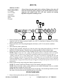
AIRLESS SPRAY EQUIPMENT
1997 VERSION
BEGINNING AT
SERIAL NUMBER
140056
SAFETY, OPERATING AND
MAINTENANCE INSTRUCTIONS
AND PARTS LIST
Do Not attempt to operate this machine until you have read and
understand ALL safety precautions and operating instructions.
Equipment and chemicals when used improperly can be
H.E.R.O. INDUSTRIES
41
1150GSD MANUAL - “B” VERSION
H.E.R.O. WARRANTY
H.E.R.O. INDUSTRIES LTD., guarantees this airless pump to be free of
defects in materials and workmanship to the original owner, for a period of
one full year from the date of purchase.
The warranty entitles the owner to parts replacement at no charge. The
parts replacement warranty is valid for any necessary replacement, whither
caused by material or workmanship defect or simple wear. The hydrapulse
membrane (part# 4-04-22-4500) is warranted for LIFE. Installation costs
for the hydrapulse membrane is provided for the first 12 months only. H.E.
R.O. Industries Ltd. offers no warranty on the intake ball, outgo ball, drive
belt, hoses, gun or accessories, plastic, rubber, other soft goods or motor
used in or supplied with the H.E.R.O. sprayer.
Motor, accessories, etc., which are supplied by other manufacturers and are
attached to or supplied with the H.E.R.O. airless pump, are warranted only
to the extent that these parts are warranted by their respective
manufacturers. Warranty claims must be made directly to such
manufacturers or their local authorized service depots.
The warranty is only applicable to the original purchaser and the equipment
has been properly used, operated and maintained in accordance with all
instructions, precautions and warnings contained in this manual. For the
purpose of this warranty, damage resulting from accident, abuse, improper
cleaning or operation, fire, flood, or Act of God, is not covered.
H.E.R.O.’s liability is limited to replacing parts found to be defective or
worn and does not include; transportation costs, damage or other expenses
of any kind incurred in connection with the purchase and use of this
sprayer.
Repairs claimed under warranty must be performed at an authorized H.E.R.
O. Service Center, using only genuine H.E.R.O. parts. Parts necessary
under warranty claim will be supplied by your local H.E.R.O. Service
Center.
DO NOT return worn parts to factory without authorization.
To qualify for the warranty, the warranty card (attached to this page)
supplied with this H.E.R.O. airless pump, must be completed with
H.E.R.O. INDUSTRIES
1
1150GSD MANUAL - “B” VERSION
TABLE OF CONTENTS
For greatest user satisfaction, please familiarize
yourself with all maintenance and operational instructions
Important Safety Precautions...................................................................................................... 3-4
Introduction .....................................................................................................................................5
Operating Instructions .....................................................................................................................5
Setting Up To Spray.................................................................................................................... 6-7
Flushing The Unit ...........................................................................................................................8
Special Notes ...................................................................................................................................9
Airless Spray Painting Suggestions........................................................................................ 10-12
Trouble Shooting..................................................................................................................... 13-21
Hydrapulse Membrane Replacement ...........................................................................................22
Intake Seat Replacement...............................................................................................................23
Piston Repairs .......................................................................................................................... 24-25
Outgo Valve ..................................................................................................................................26
Prime Valve Repairs .....................................................................................................................27
Pressure Control Valve Repairs....................................................................................................28
Accessories ....................................................................................................................................29
Parts List And Descriptions .................................................................................................... 30-34
Exploded Unit Diagram .......................................................................................................... 35-36
Depot List ................................................................................................................................ 37-40
IMPORTANT
NOTE: AS WITH ALL MECHANICAL EQUIPMENT, PROPER OPERATING AND
MAINTENANCE PROCEDURES ARE REQUIRED TO KEEP YOUR H.E.R.O. AIRLESS
PUMP PERFORMING TO YOUR SATISFACTION. THE FOLLOWING SAFETY,
OPERATING AND MAINTENANCE INSTRUCTIONS ARE IMPORTANT.
Read and understand this manual completely, especially with regard to all safety precautions. Read
and follow instructions on all warning labels on your equipment. Keep the warning labels clean and
readable at all times. Order new labels from your local distributor or from H.E.R.O. Industries Ltd. if
needed.
The manufacturer shall not be responsible for any loss, damages, or injury of any kind or nature
whatsoever resulting from the use the equipment other than in strict compliance with the instructions,
cautions and warnings contained in this operating and instruction manual and as displayed on the face
of the equipment.
This system is capable of producing 2400 psi. ( spray pressure ). To avoid rupture and injury DO
NOT operate this pump with components rated less than 3000 psi. working pressure (including but
not limited to spray guns, hose and connections).
Before servicing, cleaning or removing of any part, shut off power and relieve pressure.
IMPORTANT SAFETY PRECAUTIONS
H.E.R.O. INDUSTRIES
2
1150GSD MANUAL - “B” VERSION
WARNING
NEVER PLACE FINGERS NEAR SPRAY TIP OF GUN. NEVER POINT GUN TOWARD
ANY PART OF YOUR BODY, OR THAT OF ANY OTHER PERSON. MATERIAL ISSUING
FROM THE SPRAY TIP IS AT HIGH PRESSURE. IF FINGERS, OR ANY PART OF THE
BODY ARE PLACED NEAR THE TIP OF THE SPRAY GUN, IT IS POSSIBLE THAT THE
SPRAY COULD BREAK THE SKIN AND INJECT SOME OF THE SPRAY MATERIAL. IF
INJURY DOES OCCUR, SEEK THE IMMEDIATE ATTENTION OF A MEDICAL DOCTOR.
BE PREPARED TO INFORM THE DOCTOR WHAT FLUID WAS INJECTED, IF THE
INJURY IS OF AN INJECTION NATURE. EQUIPMENT AND CHEMICALS WHEN USED
IMPROPERLY CAN BE DANGEROUS!
NEVER place any part of the body in front of the spray tip or aim the gun toward any part of the
body.
NEVER point the gun toward any individual.
NEVER treat any injury as a simple cut. If injury does occur, seek immediate medical attention. Be
prepared to inform the doctor what fluid was injected.
NEVER allow another person to use the sprayer unless he is thoroughly instructed on its
operation and has read all safety precautions in this manual and all safety warning labels attached to
unit.
NEVER use around children.
NEVER attempt to perform any maintenance or service on any part of the unit spray system
without first;
1. Turn off the engine.
2. Turn the engine switch to “OFF” position.
3. Relieving all pressure in the pump by triggering the gun.
4. Locking gun trigger in "LOCKED" position, with gun locked closed.
NEVER operate the sprayer without the tip guard complete and in place.
NEVER spray any material in the vicinity of open flame, pilot lights, electrical outlets or any
other source of ignition.
NEVER spray volatile materials with flash points lower than 140 F (60 C).
NEVER attempt to stop any leakage in the paint line or at any fitting with your hand or any part of
your body. Immediately shut off the unit should leakage occur.
NEVER allow paint hose to become kinked, or to vibrate against rough or sharp surfaces.
NEVER operate the unit at pressures higher than the pressure rating of the lowest rated
component in the system, or at pressure higher than factory preset.
NEVER spray in an enclosed area. The spraying area must be well ventilated to safely remove
chemical vapors.
NEVER operate the unit with worn or damaged accessories, or with accessories other than those
supplied by H.E.R.O. Industries, unless the accessories have been first specifically approved in
writing by H.E.R.O. Industries Ltd.
NEVER allow the unit to be serviced or repaired anywhere other than an authorized H.E.R.O.
Service Center, or with other than genuine H.E.R.O. parts or components.
NEVER leave unit unattended without first shutting off, triggering the gun to relieve all pump
pressure, and setting the trigger lock on gun in "LOCKED" position, with gun locked closed.
ALWAYS
ALWAYS follow H.E.R.O. recommendations for operation and safety completely.
H.E.R.O. INDUSTRIES
3
1150GSD MANUAL - “B” VERSION
ALWAYS set trigger lock on gun in "LOCKED" position when not in use, with gun locked close.
ALWAYS check connections and fittings for tightness before operating the unit.
ALWAYS locate the unit in a well ventilated area a minimum of 25 feet from the spray area.
ALWAYS ground the unit, the paint containers, and the object being sprayed to eliminate static
discharge. Ensure that all these objects remain grounded throughout the entire spraying operation.
ALWAYS use accessories and components approved for at least 3000 psi (working pressure) in the
spraying system.
ALWAYS use accessories and components supplied by H.E.R.O. Industries Ltd., or specifically
approved in writing by H.E.R.O. Industries Ltd. on with the unit.
ALWAYS examine accessories for wear or damage before operating the unit.
ALWAYS use lowest possible pressure when flushing and cleaning the unit, and hold the gun firmly
against a metal container to reduce static discharge possibility.
ALWAYS wear a face filter mask when operating the unit.
ALWAYS ;
1. Turn off the engine.
2. Turn the engine switch to “OFF” position.
3. Relieve all pressure in the pump by triggering the gun.
4. Lock gun trigger in "LOCKED" position, with gun locked closed before attempting to perform
any maintenance or service on any part of the unit spray system.
ALWAYS wear safety glasses when operating the unit.
ALWAYS ensure fire extinguishing equipment is readily available and properly maintained in the spray
area.
ALWAYS observe good housekeeping and keep the spray area free from obstructions.
ALWAYS be aware that certain chemicals may react with aluminum, carbide, or other components in
the pump system. Read the manufacturer's label on all materials to be sprayed, and follow the
manufacturer's recommendations. If in doubt, consult your material supplier to be sure.
H.E.R.O. AIRLESS SPRAY PAINTING
Welcome to the world of H.E.R.O. airless paint spraying. We are sure you will enjoy owning and operating
your new H.E.R.O. model 1150GSD. With H.E.R.O. airless spray equipment you will avoid the
H.E.R.O. INDUSTRIES
4
1150GSD MANUAL - “B” VERSION
inconvenience and mess of overspray. You are spraying paint, not air, and the paint is driven to the painting
surface in a clean, fan shaped spray which penetrates all cracks and corners. To attain these results, you must
adjust the pressure as low as possible. We recommend that you become familiar with your H.E.R.O. unit.
Discuss with your dealer the useful accessory items he has to offer - various types of tips, extension poles for
hard to reach areas, extra hose, etc. Use of accessory items is often the difference between a good job and an
excellent one!
1997
HYDRAPULSE
“B” VERSION
BEGINNING AT
SERIAL NUMBER
INSTRUCTIONS
OPERATING
140056
WARNING
Do not attempt to operate this machine until you have read and understood all safety precautions and
operating instructions. Equipment and chemicals when used improperly can be dangerous.
Your H.E.R.O. airless sprayer has been fully factory tested prior to shipment.
BEFORE STARTING YOUR H.E.R.O. PUMP....
CHECK to ensure that the shipping seal has been removed from under the cap on the hydraulic tank.
Hydraulic tank should be at least 3/4 full of H.E.R.O. LVO hydraulic fluid.
CHECK all fittings and connections in the pump system, hose, and gun to ensure that they are tight.
CHECK to ensure that there is a spray tip in the gun, and that the tip is the correct size for the coating you
are to spray. ( There are various tips available, for each type of coating or configuration. See " Airless Spray
Tip " on page 11 , for proper tip selection.
CHECK to ensure that you have H.E.R.O. strainer bags, H.E.R.O. Wonder Wash, appropriate thinner for
the paint, a waste container, and any other accessories you may require for the job.
READ THIS MANUAL THOROUGHLY.
READ THE HONDA ENGINE MANUAL SUPPLIED WITH THE UNIT. FOLLOW ALL THEIR
RECOMMENDED PROCEDURES FOR “START-UP” AND OPERATION
SETTING UP TO SPRAY
1.
2.
Remove unit from shipping carton.
Attach intake siphon assembly (ref# 1) to intake elbow (ref# 8). The intake elbow provides a swiveling
connection during assembly only. Two wrenches are required to tighten these fittings. When sufficiently
H.E.R.O. INDUSTRIES
5
1150GSD MANUAL - “B” VERSION
tightened the siphon hose will no longer swivel or move, as such, ensure the siphon hose is positioned in
the desired direction prior to making the final tightening. The desired position is straight back from the
intake. Use caution to avoid over tightening which may result in cracked or broken fittings.
7
11
3. Attach prime hose (ref# 51) to
(ref#50). Secure with clamp (ref# 52).
4. Attach paint hose to outgo tee 8
5. Attach gun to paint hose.
NOTE; Spray tip and tip guard
attaching
to hose.
prime valve (ref# 36) hose barb
(ref# 35).
should be attached to gun prior to
36
35
Paint
Hose
50
6. P l a c e
51
52
i n t a k e
s i p h o n
assembly
clean 5 gallon pail.
7. Install strainer bag (accessory item 5GAL SB) in pail and secure
with large rubber band (accessory item 106).
NOTE; Strainer bag must remain 4 inches from the bottom of pail
8. Trigger gun to release any pressure in the unit. Use extreme caution
to ensure that the gun is not directed towards anyone or any object
which may be damaged.
NOTE; Unit may contain storage solution.
9. To remove storage solution, add one gallon of thinner, compatible
with the type of paint to be used, to the siphon pail.
into a
Strainer bag and siphon tube.
ALWAYS
strain paint before
starting
H.E.R.O. INDUSTRIES
6
1150GSD MANUAL - “B” VERSION
SETTING UP TO SPRAY - CONTINUED
75
46
10. Turn pressure control knob (ref# 75) counter clockwise to lowest pressure
setting.
11. Observe and perform all pre-operation checks as required by the engine
manufacturer, ( Honda ). See your Honda owner’s manual.
12. Start engine. See Honda owner’s manual for correct procedures.
13. Turn prime valve knob (ref# 46) counter clockwise until fully open. Allow
thinner to circulate back into the siphon pail for a few minutes. Then turn the
prime valve knob clockwise to close the valve ( close tightly ), and direct the
flow to the paint hose and gun. Leave the pressure setting low.
14. Trigger gun into a waste container.
15. Remove rinse / prime fluid and pour paint through strainer bag into siphon pail.
16. Repeat step 13, until paint flows freely.
NOTE; Never turn prime valve back to "prime" position when the unit is
under pressure.
NOTE: The thicker paint will require a longer time to complete the initial
prime circulation through the prime valve. Leave the valve in the prime
position to ensure the complete removal of all air and pre-prime fluid. Several
minutes may be required, particularly with thicker viscosity products.
17. Spray a test pattern. Begin by spraying a test pattern onto old newspaper or
other scrap material.
18. Increase the pressure, slowly at first, by turning the pressure control knob
clockwise. Continue increasing the pressure until the spray pattern is
uniformed from top to bottom, with no heavy areas. Secure pressure control
setting, by turning the silver lock ring (ref# 77) counter clockwise until snugly
against the face of the pressure control knob. If heavy areas are still visible at
maximum pressure setting, thin the paint with the correct thinner, according to
the paint manufacturer's recommendations.
19. Spray paint.
Paint Straining
It is recommended that all products entering the sprayer, be pre-strained to
remove any large particles and contaminants, BEFORE they are drawn into
the sprayer. The strainer bag should remain in place throughout the painting
operation. This will prevent foreign matter from falling into the bucket and
contaminating the previously strained paint. The gun filter should not be relied upon to do all the paint filtration. Any dirt, grime or other undesirable
particles which reach the gun filter have passed through the entire paint
pump and have possibly created unnecessary damage and inconvenience.
Always strain the paint before siphoning.
H.E.R.O. INDUSTRIES
7
1150GSD MANUAL - “B” VERSION
FLUSHING THE UNIT AT SHUTDOWN
OR COLOR CHANGE
If shutting down for a short period of time, it is sufficient to trigger the gun to
relieve pressure. Then set the safety lock on gun to "locked" position with the
gun locked closed and immerse the gun in a container of the correct thinner for
the paint you are spraying.
1.
2.
Remove spray tip from gun.
Turn pressure control knob counter clockwise to low pressure setting. Only
use sufficient pressure to allow material to move through the sprayer. DO
NOT operate at or near full pressure.
3. Remove siphon assembly from paint container.
4. Trigger gun, back into paint container, until unit runs dry.
NOTE: Pump and spray hose will continue to contain paint. This paint may
be recovered by placing prime hose into paint container and draining the
remainder while re-priming with cleaning fluid. See step 5* and 6*.
5. Place siphon assembly in container of correct thinner, for the spray product
being used,, and prime the pump as shown in step 13, of "Spraying". *See
special notes from step 4. Allow thinner to circulate back into the container
for a few minutes to flush the prime valve.
6. Close prime valve.
7. Trigger gun into paint container until thinner comes through. *See special
notes from step 4. Re-direct flow into waste container and continue spraying
until thinner runs clear. Heavily soiled thinners may have to be changed to
complete cleaning job.
8. Lift siphon assembly and allow pump to run dry.
9. Repeat procedure using a gallon of H.E.R.O. Equipment Wonder Wash
solution. If not using Wonder Wash, unit must not be stored with water. Only
store with a non corrosive material ( Paint thinner, solvent ).
10. Switch unit "off" and trigger gun to relieve remaining pressure.
11. Remove and rinse gun handle filter in correct thinner.
SPECIAL STORAGE INSTRUCTIONS
In areas where the sprayer is NOT used 12 months of the year, special preparations
must be used for winter or off season storage. Because solvents evaporate quickly,
they should not be used for long term storage. A petroleum based solution ( solvent
and oil ) should be used as an extended storage material. DO NOT allow storage
solution to freeze in the sprayer.
H.E.R.O. Equipment Wonder Wash, available from your H.E.R.O. distributor,
will provide the added cleaning benefits of solvent at a much lower cost. Suitable
as a short term ( 1-2 days ) storage solution only
SPECIAL NOTES AND INSTRUCTIONS
H.E.R.O. INDUSTRIES
8
1150GSD MANUAL - “B” VERSION
NEVER LEAVE THE UNIT UNDER PRESSURE WHEN NOT SPRAYING (ENGINE TURNED
OFF). RELIEVE PRESSURE BY TRIGGERING GUN. NEVER STORE THE UNIT WITH PAINT
OR WATER IN THE PUMP SYSTEM, EVEN OVERNIGHT.
NEVER attempt to start the engine when the unit is under pressure. Relieve pressure and follow
instructions in "Setting up to spray"
Avoid operating the unit while tilted. Keeping it level assures greater operating efficiency.
Always follow flushing and cleaning instructions exactly.
In hot weather, locate unit in shade.
Regularly check the level of H.E.R.O. LVO hydraulic fluid in the hydraulic tank. It should be kept near
full, top up as needed with only genuine H.E.R.O. LVO hydraulic fluid.
Crankshaft eccentric bearing should be greased at regular intervals consistent with hours of use. Use
MO-2 grease (i.e. common auto grease) approximately every 10 hours of operation.
A minimum 50’ and a maximum of 300’ of airless spray hose may be used.
NOTE: 50’ x 3/8” paint hose ( part # 117 ) should be used for every 50’ x 1/4” paint hose
( part # 114 ) over 100’.
100’ total length of paint hose = 2 of 50’ x 1/4” paint hose.
150’ total length of paint hose = 2 of 50’ x 1/4” paint hose and 1 of 50’ x 3/8 paint hose.
200’ total length of paint hose = 2 of 50’ x 1/4” paint hose and 2 of 50’ x 3/8 paint hose.
250’ total length of paint hose = 3 of 50’ x 1/4” paint hose and 2 of 50’ x 3/8 paint hose.
300’ total length of paint hose = 3 of 50’ x 1/4” paint hose and 3 of 50’ x 3/8 paint hose.
Product viscosity, altitude ( feet above sea level ) and vertical reach can effect pump performance and
special accessories may be required. Product viscosity may have to be further reduced at higher
elevations. The larger diameter 3/8” paint hose should be used.
Check drive belts ( part# 66/100 ) tension frequently. The belt will stretch with use, and should be
adjusted after 20 hours of operation and again after 50 hours. Periodic checks after 50 hours should be
made. Failure of the drive belt is not covered by the equipment warranty, so proper maintenance of the
belt is important.
Regularly check fittings, bolts, nuts and connections for damage. Tighten, adjust or replace as required.
Check crankshaft alignment often. An out of alignment crankshaft will cause the damage to the
eccentric bearing.
GAS ENGINE
Check the engine oil level daily. Top up only with the manufacturer’s recommended oil. Running the
engine with insufficient oil can cause serious engine damage.
Check the engine air cleaner daily. NEVER operate without an air cleaner.
Use only UNLEADED or lowleaded gasoline.
The engine requires regular operation and should not be stored for prolonged periods without operating.
Run for a minimum 15 minutes each week while in storage.
Remove gas before storing.
Have the engine professionally serviced by an approved service technician on a regular bases as
recommended by the manufacturer ( Honda ).
DO NOT adjust engine operating speed ( RPM ). The engine is factory set for optimum performance.
DO NOT use engine RPM to control spray performance, always adjust pressure with “Pressure Control”
AIRLESS SPRAY PAINTING
H.E.R.O. INDUSTRIES
9
1150GSD MANUAL - “B” VERSION
SUGGESTIONS AND TECHNIQUE
A good airless spray application is the result of many factors. Surface preparation, which includes cleaning
and degreasing, priming, material compatibility, quality finish product and correct application technique, are
all important to the finished results.
The key to all good applications is a good spray gun technique. The finished results are what the client will
look at and base his opinion on. Your skill and abilities are as important as good equipment and good paint.
Proper application techniques can easily be learned by using the following simple guidelines. If you are not
familiar with the basic spray techniques we recommend that you study this portion of the manual and
practice the techniques shown. Practice your technique on scrap cardboard or old newspaper until you feel
confident.
FOR EXCELLENT RESULTS, READ AND PRACTICE THESE TECHNIQUES
1.
2.
3.
4.
5.
6.
7.
Always strain all paint through a H.E.R.O. strainer bag.
The most common reason for airless sprayers to malfunction is foreign matter jamming the valves or
plugging the tip. Always strain the paint before putting through the pump.
Always spray at the lowest pressure setting which will provide a uniform spray fan. (fig. 1, page 10)
Adjust pressure control knob so that paint is completely atomized . Insufficient pressure will result in
"tailing". Too much pressure will result in excess fog and over spray, excess tip wear, and increased
sprayer wear and tear. See setting up to spray, page 5.
Always spray at right angles to the surface being sprayed. (fig. 2, page 10)
Angling or arcing the nozzle toward the surface will cause uneven coverage and excessive
overspray.
Always hold spray gun 12-15 inches from spray surface. (fig. 3, page 10)
Too close and the fan width will be reduced and material will be applied too heavily (runs).
Too far from the surface and you will have excessive overspray and light coverage (transparent).
Always move the gun parallel to the surface being sprayed, at a consistent speed.
This avoids uneven coverage (thick or thin areas).
Always start the spray stroke before triggering the gun and release the trigger before completing the
stroke. (fig. 4, page 10)
This avoids heavy build up of paint at either end of the spray stroke.
Always lap your spray pattern by one half. (fig. 5, page 10)
This assures full coverage of the surface being painted.
AIRLESS SPRAY PAINTING
SUGGESTIONS AND TECHNIQUE
H.E.R.O. INDUSTRIES
10
1150GSD MANUAL - “B” VERSION
SPRAY TIP SELECTION
FIG.
Poor
Good
Tailing
Good Pattern
FIG.
Fog, Overspray
FIG.
FIG.
FIG.
FIG.
H.E.R.O. INDUSTRIES
11
1150GSD MANUAL - “B” VERSION
TIP SIZE
.021
.018
.015
.013
.011
.009
FOR APPLICATION OF
Exterior Latex on large unobstructed areas.(max. size allowed) ( 60 OZ. )
Interior Latex, Exterior Latex, Shake Paint, Exterior Flat Paints. ( 46 OZ. )
Alkyd Flat Enamel, Interior Latex, Semi-Gloss Enamel, Stains. ( 30 OZ. )
Fine ground Gloss Enamels, and good quality Stains. ( 23 OZ. )
Clear Varnishes and Lacquers. ( 15 OZ. )
Clear Varnishes and Lacquers. ( 10 OZ. )
NOT: The above volumes achieved with gun wide open for 1 minute and pump spraying at
2000psi. All volumes are approximate. To test worn tips, spray water through the tip at 2000 psi.
for 1 minute. Spray into bucket and weigh amount (less weight of bucket). If it is substantially
greater than what is listed above, then the tip should be discarded or reclassified. As a tip wears, the
hole gets larger and the fan pattern becomes narrower.
ORIFICE SIZE
All tips are rated by the size of the orifice or bore size. The bore size is measured in thousandths of an inch
( .018 = 18 thousandths of an inch ). The size of tip required is based on the consistency of the material to be
sprayed. The thicker the paint, the larger the tip size required. Always consult the product label or ask the
paint retailer for the manufacturer's recommendations with regard to proper tip sizes.
FAN WIDTH
Fan width or pattern width is determined by the spray tip's "fan width" classification. This size is measured in
inches, and is determined when spraying 12 inches from the spray surface. Various methods of noting the fan
widths are used by tip manufacturers. Ask your distributor for assistance.
NOTE: Two tips having the same tip size, but different fan widths will deliver the same amount of paint
over a different area (wider or narrower strip). A spray tip with a narrow pattern width makes it
easy to spray in tight places. Use only good quality, high-pressure tungsten carbide spray tips.
SPRAY TIP REPLACEMENT
During use, especially with Latex paint, high pressure and material abrasion will cause the orifice to grow
larger. As the orifice grows larger, the fan width grows smaller. Replace tips before they become excessively
worn. Worn tips waste paint, cause overspray, make cutting in difficult, and decrease sprayer performance.
NOTE: When using Latex paint, a spray tip will wear at the rate of one size for approximately every 100
gallons of material sprayed.
An excessively worn tip can be the cause of apparent operating problems with the unit. If a tip is worn
past the aperture size which the unit can support, pulsation will become evident in the spray fan/pattern.
Added strain is placed on the Hydrapulse membrane as it attempts to keep the spray pressure consistent.
When the tip wears beyond .031, its is releasing more material than the unit is bringing in. The natural
reserve of product in the paint chamber is reduced and harm to the membrane begins. ALWAYS check
your tips for wear when trouble shooting the equipment. The 1150GSD can support up to a maximum of
a one .031 tip or two .021 tips.
TROUBLESHOOTING
Hydraulic Energy Regulated Output (H.E.R.O.) is more than just our name, it is the bases for the
operation of the pump. It is the regulation or control, of hydraulic energy, which allows the equipment to
H.E.R.O. INDUSTRIES
12
1150GSD MANUAL - “B” VERSION
build and then deliver or have an output of pressure. Once you have a basic understanding of the operation of
the equipment and the effect created in one area and how it will effect operation in another area, you will be
better able to diagnose and make repairs.
All H.E.R.O. hydrapulse membrane pumps are made up of two (2) distinct pumps. The first, and most
important pump is the hydraulic pump. The hydraulic system is made up of two valves, the hydraulic intake
valve (ref# 66) and the hydraulic outgo valve, known as the hydraulic pressure control valve (ref# 74). The
second pump is known as the paint or material pump. The paint system is made up of two basic valves, the
paint intake valve assembly (ref# 11-18), paint outgo valve, (ref# 26). A third valve, known as a prime valve
(ref# 36) is used during the priming procedure, (see "setting up to spray"). For correct operation, all five
valves must be in good working condition. For this manual we will refer to the two systems as "hydraulic"
and "paint".
At the center of these two pumps is the hydrapulse membrane. The hydrapulse membrane is a flexible nylon
disc which transfers the energy (pressure) created by the hydraulic pump, to create energy (pressure) in the
paint pump. The function of the hydrapulse membrane is to create a barrier between the hydraulic oil and the
spray material and transfer the energy created.
To fully understand and trouble shoot a H.E.R.O. pump, always keep in mind that "for every action,
there is an opposite or corresponding re-action". For every action of the hydraulic intake valve (ref# 66),
there is an opposite re-action of the hydraulic outgo valve (ref# 74). At the same time there are
corresponding re-actions taking place within the paint pump. This means that as the hydraulic intake valve is
opening, so is the corresponding paint intake valve, and while the hydraulic outgo valve is closing, so is the
corresponding paint outgo valve. The operation and function of each valve is discussed at the end of this
section.
For correct operation to begin, the hydraulic system must be fully primed and all air must be removed
( see "purging" page 18 ). Operation begins with piston in the backward position (fig.# 2). At this point the
hydraulic intake is open, while the hydraulic outgo valve is closed. The corresponding paint valves are in
similar positions.
As the piston moves forward, it pushes hydraulic oil forward. This movement of oil causes the hydraulic
intake valve to close and the hydrapulse membrane to move forward (fig.# 1). The hydraulic outgo valve will
remain closed until sufficient pressure is created to cause it to open. While the hydraulic valves are operating
a corresponding re-action is taking place in the paint valves. The forward movement of the hydrapulse
membrane pushes the paint, causing the paint intake valve, (ref# 11-18) to close. The trapped paint requires a
means of release, so it forces the outgo valve, (ref# 26), to open and paint flows to the gun.
Fig. 2
Fig. 1
H.E.R.O. INDUSTRIES
13
1150GSD MANUAL - “B” VERSION
TROUBLESHOOTING
The backward movement of the piston, creates a vacuum in the hydraulic system. This causes the
hydraulic outgo valve to close and the hydraulic intake valve to open (fig# 1). Opening of the hydraulic
intake valve allows a new supply of hydraulic oil to enter the system, replacing the oil which was used on the
forward stroke. Once again a corresponding re-action is taking place in the paint pump. The hydrapulse
membrane is being pulled backward by the hydrapulse membrane spring, (ref# 56). The backward
hydrapulse membrane movement causes a vacuum in the paint pump. This vacuum causes the intake valve
to open, allowing a new supply of paint to enter. The corresponding paint outgo valve is drawn closed by the
vacuum created by the hydrapulse membrane.
These operations are repeated at a rate of 750 times a minute. These continuously repeated actions draw
paint into the pump, pressurize it, and then deliver it to the gun. The failure, of any one valve, to operate
correctly will effect the overall equipment performance. Each of the five valves mentioned earlier, have an
important function and will effect the overall performance of the unit if not performing correctly.
HYDRAULIC INTAKE VALVE (REF# 66, PART # 4-30)
The hydraulic intake valve, is a small vacuum valve which controls the hydraulic oil entering the
hydraulic pump/cylinder area. Once the oil has past through the valve it is prevented from returning. The
valve is commonly called a “one way check valve”. Valve failure will result in the hydraulic pump being
unable to build pressure, and the hydrapulse membrane will stop moving. Spray pressure will cease.
HYDRAULIC OUTGO VALVE (REF# 74, PART# 4-27C)
The hydraulic outgo valve, better known as the "pressure control valve", is used to control the units
operating pressure. The valve is fully adjustable from 0 psi. to 3000 psi. By turning the pressure control valve
knob (ref# 75) clockwise the pressure is increased. The hydraulic pump continues to build at all times and
must have a means of releasing this pressure. Pressure applied to the P.C. ball, (ref# 88) will keep it lodged in
the P.C. seat (ref# 87) until the internal hydraulic oil pressure is sufficient to cause it to open. The point at
which the oil is released is equal to the level set by the control knob. As components within the pressure
control valve wear, the valve looses its ability to maintain or reach the required pressures (see "low static
pressure").
PAINT INTAKE VALVE ASSEMBLY (REF# 11-18)
The paint intake valve is made up of eleven items, endcap (ref# 11), washer (ref# 12), seat (ref# 13)
intake ball (ref# 14), spring (ref# 15), o-ring (ref# 16), ball guide (ref# 17), and ball stop (ref# 18). The intake
valve controls the incoming flow of spray materials and is responsible for keeping them from returning to the
source. The ball must be able to create a complete seal on the seat, otherwise pressure will be lost. A worn
intake valve will permit correct static pressure, but supply lower spray pressure. A worn intake ball will
become smaller in diameter and loose its ability to seal at the seat. A worn seat will develop a large step in
the area where contact with the ball is made. This can cause the intake ball to distort in shape making the ball
egg shaped. If the valve assembly becomes warm to the touch, this may be a sign of a loose or worn seat
caused by wear or improper compression caused by a worn intake washer (ref# 12). The intake washer (ref#
12), acts as a compression washer insuring the seat (ref# 13) remains pressed into the endcap (ref# 11). The
seat must remain firmly pressed into the endcap at all times, through the correct assembly of parts listed, and
the correct bolt torque. Replace the intake washer (ref# 12) each time the endcap is removed. See page 23 for
details.
TROUBLESHOOTING
H.E.R.O. INDUSTRIES
14
1150GSD MANUAL - “B” VERSION
PAINT OUTGO VALVE ( REF# 26, PART# 4-611C )
The paint outgo valve monitors and controls the flow of spray materials as it leaves the sprayer. It also
works together with the paint intake valve, to build paint pressure as specified by the setting made by the
hydraulic outgo valve (pressure control valve). A worn outgo valve will result in pulsation in the spray
material and cause the paint hose to jump and vibrate vigorously.
PRIME VALVE ( REF# 36, PART# 4-603 )
The prime valve is used at the beginning and end of the spray operation (see "setting up to spray"). The
function of the prime valve is to assist in removing air from the paint pump when beginning to spray. It is
necessary to remove all air from the paint pump so that the spray material can replace it. The pump will
function without the prime valve, however, the initial priming procedure would require considerably longer
to complete. During the priming procedure the hydrapulse membrane is exposed to its greatest amount of
stress. Use of the prime valve and a lightweight thinner, which is compatible with the intended spray
material, will reduce hydrapulse membrane stress and reduce priming time. The prime valve will also allow
you to remove any unused paint left in the pump and hose at the completion of a job. When the prime valve
is open the material is pumped through the paint intake and outgo and back to the source by way of the prime
valve. When closed, no material should be escaping from the prime valve return hose (ref# 51). If material
escapes through the prime valve return hose, when the valve is closed, spray pressure at the gun will be
reduced.
The solution to almost all problems can usually be found in the paint side valves. However, before
performing any repair or looking further, the following are things which can cause an apparent sprayer
failure, without any mechanical problem. ALWAYS check these items before preceding.
1.
2.
3.
4.
5.
6.
7.
Circuit breaker open or fuse blown
.
Engine fuel line closed.
Engine switch set to “OFF”.
Spark plug wire loose or disconnected.
Pressure control knob loose or missing
Spray tip plugged.
Spray tip worn out.
8. Gun handle filter plugged.
9. Paint hose plugged.
10. Loose fitting or hole in siphon hose.
11. Intake siphon hose plugged.
12. Siphon screen missing or plugged.
13. Sprayer under pressure when restarting.
14. Strainer bag plugging siphon screen.
UNLESS YOU ARE KNOWLEDGEABLE ABOUT THE REPAIR OF HIGH PRESSURE
EQUIPMENT, DO NOT ATTEMPT TO REPAIR AN AIRLESS SPRAYER YOURSELF. ALWAYS
FOLLOW ALL SAFETY PRECAUTIONS. THE H.E.R.O. SERVICE VIDEO TAPE (1-620-VHS OR 1620-BETA) WILL PROVIDE COMPLETE SERVICE TRAINING. SEE YOUR H.E.R.O.
DISTRIBUTOR TO PURCHASE A COPY.
TROUBLESHOOTING
H.E.R.O. INDUSTRIES
15
1150GSD MANUAL - “B” VERSION
PRESSURE TEST
To verify the operation of an airless sprayer, use of pressure gauge is required. A pressure gauge (min. 3000
psi) installed at the gun, using a new .021 tip, and not less than 50 feet of H.E.R.O. airless spray hose is
needed. If you do not have access to these items, your local H.E.R.O. authorized service center will be able
to perform this test. Your model 1150GSD is manufactured to perform at;
2650 psi -- Static pressure, with lock ring (ref# 77) on pressure control valve (ref# 74).
1950 psi -- Pressure drop, when gun trigger is squeezed.
2250 psi -- Spraying pressure, after recovery time.
If your unit is unable to perform to the above pressure levels consult the troubleshooting guide for the
required repair procedure.
HYDRAPULSE MEMBRANE TEST
If your unit is disabled and you are unable to perform a pressure test, use the following procedures for
determining the area to repair. This test will divide the two halves of the equipment (hydraulic from paint)
and make identification of your solution easier to obtain. This test is commonly referred to as the
"Hydrapulse membrane Test"
The solution to almost all problems can be found in the paint side valves, due to the increased wear from
contact with the abrasive paint/spray materials. Intake valve (ref# 11-18), Outgo valve (ref#26), and Prime
valve (ref# 36) make up the three paint valves. Refer to pages where exploded views of these valves are
shown. To eliminate the hydraulic side of the pump (piston side of hydrapulse membrane) as a source of
problems;
1. Remove the intake valve end cap (ref# 11) by removing the four cap screws (ref# 9 ). The intake valve
assembly, (ref# 1118), will generally come off as an entire assembly, requiring no f u r t h e r
dismantling. If the ball guide (ref# 17) and ball stop
(ref# 18),
remain in the paint head, they can be pried free
w i t h
a
screwdriver.
2. Start unit.
3. Increase the pressure by turning the pressure control knob
11
(ref# 71) clockwise to full pressure.
4. Put pressure on the center of the exposed hydrapulse
membrane with the handle of a screwdriver or other blunt
9
object.
NOTE: The hydrapulse membrane is located between the
paint head (ref# 21) and the hydraulic head (ref# 59)
5. If you are UNABLE to stop or alter the hydrapulse
membrane's movement, then the hydraulic side is operating
properly. The problem is located in the “Paint” pump. See
troubleshooting guide for additional information.
TROUBLESHOOTING
SITUATION
POSSIBLE CAUSE (REMEDY)
H.E.R.O. INDUSTRIES
59
16
21
1150GSD MANUAL - “B” VERSION
GASOLINE ENGINE WON'T START/RUN
1. Pump under pressure. (reduce pressure setting by turning pressure control knob counter-clockwise,
trigger gun to relieve pressure).
2. Fuel line valve closed. ( open fuel line valve. See Honda owners manual ).
3. Engine switch in “OFF” position. ( turn the engine switch to “ON” position ).
4. Engine out of gasoline. ( allow engine to cool, before adding appropriate levels of unleaded gas ).
5. Engine is oil contaminated. Unit and engine must remain vertical or oil from the crankcase can enter
the carburetor, air filter etc. ( see an authorized Honda service center ).
GASOLINE ENGINE STALLS/QUITS
1. See "GASOLINE ENGINE Won't Start/Run
2. Drive belt is loose. (tighten drive belts by evenly turning belt tension bolts on either side of engine
clockwise. Check tension frequently. Loose belts generally emit loud squealing noises).
3. Unit primes, builds pressure, but pump “seizes” or “stops” when gun is triggered. ( loose belts, tighten).
4. Engine requires tune-up. ( see an authorized Honda service center ).
TOTAL LOSS OF PRESSURE, HYDRAPULSE MEMBRANE MOVEMENT CANNOT BE STOPPED
OR ALTERED. (SEE "HYDRAPULSE MEMBRANE TEST")
1. Paint too thick. (thin paint according to manufacturer's recommendations).
2. Intake ball (ref# 14) worn or jammed opened/closed. (remove intake endcap (ref# 11) and ball guide
(ref# 17). Inspect intake ball,(ref# 14), to ensure it is free, round, and has no nicks or cuts. Inspect ball
guide for excessive "bashing out" on the internal walls. Excessive wear causes the ball to become "lost"
and unable to locate the seating surface. Inspect for foreign material jamming ball. Replace parts as
needed).
3. Intake seat loose/bypassing. (remove intake endcap,(ref# 11) and ball guide, (ref# 17). Remove seat
(ref# 13), inspect inlet washer (ref# 12) for excessive compression. Inspect for any sign of material
bypass between intake seat and endcap cavity. NOTE; The proper alignment of intake parts, condition
of intake washer (ref# 12), combined with the correct bolt torque are critical to the correct function of
the intake valve. Replace the intake washer (ref# 12), each time the endcap is removed. See page 23 for
more details.
4. Outgo valve ball (ref# 30) worn or jammed. (remove outgo valve,(ref# 26). Invert valve and unthread
outgo valve upper,(ref# 31), from outgo lower,(ref# 27). Remove crush washer,(ref# 28), outgo seat,
(ref# 29), outgo ball,(ref# 30), from outgo upper tunnel. Inspect outgo ball to ensure that it is round and
free of nicks or cuts. Inspect for foreign material jamming ball. Inspect ball and cage for wear. Replace
parts as needed).
5. Outgo valve (ref# 26) incorrectly assembled. (disassemble and reassemble outgo valve, closely
following detailed instructions on page 26).
TROUBLESHOOTING
SITUATION
POSSIBLE CAUSE (REMEDY)
H.E.R.O. INDUSTRIES
17
1150GSD MANUAL - “B” VERSION
TOTAL LOSS OF PRESSURE, HYDRAPULSE MEMBRANE HAS NO MOVEMENT OR
MOVEMENT CAN BE STOPPED. (SEE "HYDRAPULSE MEMBRANE TEST")
1. Hydraulic intake valve (ref# 66) defective. (remove hydraulic feed line,(ref# 67), from hydraulic
intake valve. Plug hydraulic feed line so hydraulic fluid does not drain. Remove hydraulic intake valve
from elbow,(ref# 62). Check hydraulic intake valve to ensure that it flows in one way only, into the
cylinder. Replace if necessary. NOTE; Item cannot be repaired ).
2. Air lock created on hydraulic side of pump. (air entering hydraulic side due to loose hydraulic feed
line fittings, (ref# 67), punctured hydraulic feed line, poor seal at hydraulic intake valve, (ref# 66), or
elbow, (ref# 62). Tighten hydraulic feed line, test for leaks, or apply Teflon tape or pipe sealant on
fittings. Purge air as per detailed instructions below).
3. Pressure control valve ball (ref# 88) worn out/jammed. (remove hydraulic return line, (ref# 73), from
pressure control valve fitting,(ref# 82). Remove pressure control valve,(ref# 74), from elbow, (ref# 62).
Disassemble pressure control valve, by removing valve seat,(ref# 87), from body, (ref# 83). Inspect for
and remove foreign material. Inspect ball for wear. Install pressure control repair kit,(ref# 89), if
necessary).
4. Piston rod (ref# 94) disconnected from piston (ref# 92). (reconnect piston rod following detailed
instructions on page 24-25).
NO PRESSURE, BLUE HYDRAULIC FLUID IN PAINT
1. Hydrapulse membrane broken. (replace with complete hydrapulse membrane,(ref# 54). Closely follow
detailed instructions on page 21. NOTE; If, and only if, paint has contaminated the hydraulic side of the
pump, the entire hydraulic system must be cleaned and flushed. Make sure to remove and clean the
hydraulic tank screen,(ref# 70), during this process. Refill only with genuine H.E.R.O. LVO hydraulic
fluid. NOTE; If lacquer has contaminated the hydraulic system, the piston seal, (ref# 91), must be
changed in addition to flushing the system. Closely follow detailed instructions on page 24-25).
HYDRAULIC SIDE OF PUMP HAS BEEN REPAIRED AND REASSEMBLED, HYDRAPULSE
MEMBRANE NOT MOVING "PURGING"
1. Air lock created on hydraulic side of pump. (when the hydraulic side of the pump is working there is no
air in it. During repairs it is possible that air has been trapped in the hydraulic system. It must be
removed or the pump will not work. To purge the air from the hydraulic system; remove the pressure
control knob,(ref# 75), from the valve. Gently pull the P.C. stem,(ref# 82), out. It will pull out about
1/8". Remove the vented hydraulic cap,(ref# 72), from the hydraulic tank,(ref# 69), and install accessory
pressure cap, item 4-45-3. With a bicycle pump, apply a few pounds of air pressure to the hydraulic tank.
This will force the oil through the hydraulic system and push out any of the trapped air. Wait a few minutes.
Remove pressure cap and replace with vented cap. Restart the unit and install pressure control knob.
NOTE: Unit may be running during purging procedure to speed up the
procedure. If a pressure cap
is unavailable, simply running the
equipment for approximately 5-10 minutes with the P.C. stem pulled
out, will purge the system).
TROUBLESHOOTING
SITUATION
POSSIBLE CAUSE (REMEDY)
Accessory
Item
4-45-3
PUDDLE OF OIL APPEARING UNDER SPRAYER DURING
OPERATION
1. Hydraulic fitting loose/cracked or hydraulic lines are punctured.
(examine all hydraulic lines and fittings for cracks, breaks or looseness.
H.E.R.O. INDUSTRIES
18
1150GSD MANUAL - “B” VERSION
Replace or tighten as required).
2. Piston seals (ref# 91) worn. (remove and replace piston seals, following closely the detailed
instructions on page 24-25).
CORRECT STATIC PRESSURE, BUT REDUCED SPRAYING PRESSURE
(Check with pressure gauge, see page 16 for details).
1. Spray tip worn out/too large. (replace with new, correct sized spray tip. Tip most not exceed a newer
condition .031 tip (for 1 gun) or .021 tip (for 2 guns)).
2. Paint hose incorrect. (replace hose with genuine H.E.R.O. airless spray hose (min. 50 feet). Steel
braided hoses must not be used ).
3. Intake valve seat (ref# 13) worn. (replace intake seat closely following detailed instructions on page
23).
4. Intake ball (ref# 14) worn. (replace intake balls when signs of wear, deformation, nicks or cuts are
evident. An out of round ball is the sign of a worn intake seat,(ref# 13), and both items should be
replaced).
5. Outgo seat (ref# 29) worn. (replace seat).
6. Outgo ball (ref# 30) worn/damaged. (replace outgo ball).
7. Prime valve (ref# 36) bypassing. (start sprayer. With prime valve closed tightly, stem,(ref# 46), turned
clockwise fully, check prime valve return hose, (ref# 51), for material bypass. Repair prime valve using,
(ref# 42), if material is bypassing.
LOW STATIC PRESSURE, LOW SPRAY PRESSURE
(Check with pressure gauge, see page 16 for details).
1. Pressure control valve stem screw (ref# 80) loose. (remove pressure control knob,(ref# 75), and inspect
screw for looseness. Screw should be secured to stem, (ref# 80), with Loc-Tite. If the screw turns
independent of the stem than it must be re-secured. Secure unit so it will not move. Install pressure
gauge and .021 spray tip. Obtain a piece of wood, to use as a pusher or purchase a pressure control
adjustment tool, 27C-15. Remove pressure control screw and put some Loc-Tite 609 on threads. Turn
the screw into the stem a few turns and push it in to its maximum and read pressure. Turn the screw in
or out until 3000 psi static pressure is obtained. If you obtain a pressure which higher than 3000 psi,
trigger gun to release some pressure and continue adjusting screw until correct pressure is obtained. Let
Loc-Tite set up.
2. Pressure control ball (ref# 88) and/or seat (ref# 87) worn. (remove entire pressure control valve,
(ref# 74), from sprayer. Remove valve seat, ball, retainer,(ref# 86), and spring,(ref# 85), from valve.
Replace with pressure control repair kit,(ref# 89). Hold valve body vertical while placing in spring,
followed by retainer. Retainer should be below the valve body (approx. 3/8") when positioned correctly.
Center ball on retainer, turn valve seat into body until finger tight, using pipe dope or Teflon tape to
seal. Fully tighten using wrench.
TROUBLESHOOTING
SITUATION
POSSIBLE CAUSE (REMEDY)
FLUID BEING SPRAYED OUT OF TIP PULSATES, SPRAY HOSE LIES QUIET WHEN GUN
TRIGGER CLOSED
1. Spray tip worn out or too large. (replace with new tip of correct size. Tip must not exceed a single good
condition .031 tip or 2 .021 tips).
H.E.R.O. INDUSTRIES
19
1150GSD MANUAL - “B” VERSION
2.
3.
Paint hose incorrect type. (replace with genuine top quality H.E.R.O. airless spray hose. Steel braided
hose is not recommended ).
Too short a length of hose. (minimum 50' of airless spray hose is required. Replace or add hose until a
minimum of 50' is being used).
FLUID BEING SPRAYED OUT OF TIP PULSATES, SPRAY HOSE CONTINUES TO MOVE
VIGOROUSLY WHEN GUN TRIGGER CLOSED
1. Outgo valve (ref# 26) assembled incorrectly. (remove the outgo valve and reassemble closely following
the instructions on page 26).
2. Outgo valve ball (ref# 30) worn out or jammed. (inspect outgo ball to ensure that it is round and free of
nicks or cuts. Inspect for foreign material jamming ball. Inspect seat and cage for wear. Replace parts as
required).
PUMP SPRAYS WATER OR SOLVENT AT CORRECT PRESSURES, BUT WILL NOT SPRAY
PAINT (Check with pressure gauge, see page 16)
1. Air leak in paint intake siphon assembly. (check all fittings and hose clamps in intake assembly for
tightness).
2. Air leak in paint intake. (check for cracked or broken intake fittings. Swivel connector, (ref# 8), or hose
barb,(ref# 7), may be damaged due to over tightening. Look for small black hairline fractures. Replace
damaged parts).
3. Partial blockage in paint intake siphon hose, (ref# 5). (clean and remove any blockages from intake
siphon hose. Check to insure strainer bag is not clogging intake siphon hose).
SPRAYER DOES NOT PRIME WITH PAINT
1. Heavy bodied paint, pump dry. (refer to " Operating Instructions" and follow priming instructions
using the correct thinner for the paint you are to use).
SPRAYER DOES NOT PRIME WITH CORRECT THINNER
1. Pump completely dry.(pump may experience difficulty in priming when it is completely dry. First invert
siphon tube and pour thinner into siphon tube, to help prime dry pump).
2. Intake siphon assembly (ref# 1) has loose/damaged fittings, loose clamps, or damaged hose.(check all
fittings, hose clamps, for tightness, siphon hose for damage or holes. Replace or tighten as required).
3. Intake valve ball (ref# 14) stuck. (remove intake endcap,(ref# 11), and free ball and reassemble).
4. Outgo valve ball (ref# 30) stuck. (remove outgo valve,(ref# 26). Unthread outgo valve upper body,
(ref# 31), from outgo body lower,(ref# 27). Remove outgo seat,(ref# 29), from upper body. Free ball
and reassemble following detailed instructions on page 26).
TROUBLESHOOTING
SITUATION
POSSIBLE CAUSE (REMEDY)
SPRAY MATERIAL LEAKS AT PRIME VALVE STEM
1. Prime valve stem packings (ref# 44 or 45) defective. (replace damaged packings following detailed
instructions on page 27.
SPRAY MATERIAL LEAKS OUT PRIME VALVE HOSE WITH VALVE CLOSED
H.E.R.O. INDUSTRIES
20
1150GSD MANUAL - “B” VERSION
1.
2.
Prime not closed tightly. (tighten valve stem,(ref# 46) further)
Prime valve worn. ( install prime valve repair kit, (ref# 42). See page 27 for detailed instructions.)
SPRAY PATTERN IS SPOTTY OR UNEVEN
1. Pressure is too low. (increase pressure slowly until problem is corrected ).
2. Spray material too thick. (thin as recommended by material manufacturer).
3. Plugged siphon screen, siphon tube, gun filter or a combination. (inspect and clean or replace as
required).
4. Plugged tip. (remove and clean tip).
5. Pump malfunctioning or unsuitable for the material. (refer to other areas of troubleshooting guide and
check material requirements vs 1150GSD output abilities).
SPRAY PATTERN LEAVES LINES OR FINGERS
1. Pressure too low. (increase pressure slowly until problem is corrected).
2. Worn tip. (replace tip).
3. Tip too small for spray material. (change to larger tip or increase pressure. See material manufacturers
recommendations).
EXCESSIVE OVERSPRAY OR FOGGING
1. Pressure too high. (reduce pressure as required).
2. Material too thin. (follow material manufacturers recommendations re-thinning).
3. Tip too large. (reduce tip size).
4. Improper application technique. (refer to proper application techniques on page 10-12).
5. Too windy. (wait for wind to let up).
HYDRAPULSE MEMBRANE REPLACEMENT
(REF# 54)
H.E.R.O. INDUSTRIES
21
1150GSD MANUAL - “B” VERSION
TOOLS REQUIRED
-1/4" Allen wrench
-1/2" Open end wrench (2)
-4-45-3 (accessory item)
-Torque wrench
Removal
58
1. Remove the eight bolts securing
57
head (ref# 21) to the hydraulic head
2. Remove the material head
56
(ref# 22) and replace with the new
provided.
55
3. Place a container under pump to
oil.
4. Gently pull hydrapulse
separate it from the hydraulic head.
5. Remove the nut (ref# 58) on the
membrane stem in order to separate
54
membrane from the hydraulic
(ref# 55), hydrapulse membrane spring (ref# 56), and spring locator (ref# 57).
6. Clean all parts.
the
material
(ref# 59).
cushion
1-5/16 Inches c u s h i o n
catch hydraulic
membrane
to
hydrapulse
the hydrapulse
plastic
horn
Assembly
1.
2.
3.
Place hydraulic plastic horn over the new hydrapulse membrane.
Position the spring in the bore of the plastic horn.
Install the spring locator over the hydrapulse membrane stem and into the spring. Thread the new jam
nut onto the stem.
4. Tighten the jam nut until a measurement of 1-5/16” is obtained. The measurement is taken from the
top of the hydraulic horn (ref# 55) to the top of the spring locator ( ref# 57). See diagram above.
5. Check the assembly. The spring must be positioned in the bore of the plastic horn on one end and over
the shoulder of the spring locator on the other end.
6. Place the hydrapulse membrane assembly back into the hydraulic head.
7. Re-install the material head with the eight bolts. Torque to 30 ft. lbs.
8. Refill hydraulic oil tank and "PURGE" system following instructions on page 18.
9. Prime the pump with solvent or water and bring the pump up to full pressure (approximately 2500 psi.).
Run the pump on standby ( not triggering gun ) for about 20 minutes, to “break-in” new membrane.
10. Installation is now complete and the pump is ready for use.
REPLACEMENT OF INTAKE SEAT
(REF # 13)
H.E.R.O. INDUSTRIES
22
1150GSD MANUAL - “B” VERSION
21
19
16
15
14
13
12
TOOLS REQUIRED
-5/16" Allen wrench
-vise
-torque wrench
-screwdriver
18
17
11
1. Remove the four bolts (ref# 9) and
pull intake endcap (ref# 11), from the pump. The endcap should separate from the material head (ref# 21),
with the ball guide (ref# 17) attached. If the ball guide remains in the material head, pry out with a screw
driver.
2. Clamp endcap in vise with the ball guide facing up.
3. Pry off the ball guide and remove intake ball (ref# 14) and spring (ref# 15).
4. Remove seat from endcap. NOTE; The seat is not secured with any Loc-Tite, however dried paint
may cause difficulty in removing seat.
5. Remove the crush washer (ref# 12).
6. Thoroughly clean and inspect all parts. Replace any worn or damaged parts.
7. Place clean endcap in vise with o-ring (ref# 19) groove facing up.
8. Assembly of parts is the reverse of removal; washer (ref# 12), seat (ref# 13), and ball (ref# 14).
NOTE; A new compression washer should be used each time the endcap is removed
9. If the ball guide (ref# 17) and ball stop (ref# 18) were separated during removal, re-assemble the two.
NOTE; The step on the ball stop must face outwards ( Towards hydrapulse membrane ).
10. Place the spring (ref# 15) into the ball guide so the smaller end of the spring will contact the ball.
11. Assemble the ball guide, with spring, onto the endcap over the already installed ball and seat. Push
down on the ball guide so that the ball guide o-ring (ref# 16) locks the assembly together.
12. Place o-ring (ref# 19) in the groove on the face of the endcap.
13. Install the entire endcap assembly onto the material head with the four bolts (ref# 9). Torque bolts,
using a crisscross pattern, to 20 ft. lbs. Repeat torquing procedure using 30 ft. lbs.
NOTE: Effective March 1997, and beginning with serial number 140056, a new style Hydrapulse
“Intake” assembly is used. The changes effect the Endcap (ref# 11), Crush Washer (ref # 12), Ball Guide
(ref# 17), Ball Stop (ref# 18), and the Material Head (ref# 21). The most significant change is to the
endcap. Gone is the o-ring, formerly located under the intake seat. The endcap is machined flush and a
new crush washer is now placed in before the seat ( crush washer is placed under the seat ). The seat will
be held in place through the compression of parts during assembly.
PISTON REPAIRS
H.E.R.O. INDUSTRIES
23
1150GSD MANUAL - “B” VERSION
(REF# 90)
SPECIAL NOTES
TOOLS REQUIRED
-1/2" wrench
-11/16" wrench
-circlip pliers
-torque wrench
-grease
-vise grips
All gas driven units must remain level at all times. Tipping of the units will
cause the oil from the engine crankcase to flow into the engine air cleaner,
carburetor and cylinder head. This will cause starting and running
difficulties. Keep unit level during service.
A
B
94
1.
2.
3.
4.
5.
6.
93
92
C
91
Remove hydraulic feed line, (ref# 67) from hydraulic intake valve, (ref# 66) and also remove hydraulic
return line, (ref# 73) from the pressure control valve, (ref# 74). Plug lines to minimize oil loss. (Hint;
golf tees work well for this)
Remove the bolts, (ref# 120) passing through the side frames, (ref# 115,118), into the crossblock,
(ref# 63).
Place a drain tray under cylinder area.
Grasp the pump assembly, and pull away from the piston. Stop when piston pulls free, to allow the
hydraulic oil to drain into pan. Completely remove pump assembly from between side frames.
Remove the piston, (ref# 90) from eccentric bearing (ref# 100). Move to clean work bench for repairs.
NOTE: Repairs to the rod / seat / piston will be required if there is end play in the rod / piston
connection. This is evident if you can feel back and forth movement in the piston when you tug on it
(pulling it from the rod ). A loose fitting piston / rod can be corrected by re-packing the seat with
grease. If a pump is operated with a loose piston / rod damage to the rod, seat and piston can develop
requiring additional repairs. A pump with a loose piston / rod connection will not recover hydraulic
pressure quickly ( large pressure drop when gun is triggered ) and generally operate at lower levels of
performance.
Remove piston circlip, using circlip pliers. Remove piston from rod.
NOTE: Use extreme caution not to damage circlip or the internal circlip groove of piston.
NOTE: Piston rod circlip, washer, o-ring, and nut are not available individually. Parts are available
with the purchase of piston rod, (ref# 94) only.
NOTE: The circlip will have one sharp edge and one smooth edge. The smooth edge should be towards
the washer. If reversed, the rod will continually pull out of the piston.
PISTON REPAIRS
7.
Remove bronze piston rod seat, (ref# 93) from piston, (ref# 92).
H.E.R.O. INDUSTRIES
24
1150GSD MANUAL - “B” VERSION
8.
9.
10.
11.
12.
13.
14.
15.
16.
17.
18.
19.
20.
21.
22.
23.
24.
Examine all parts for wear or damage. Replace as required.
Fill the center cavity of piston rod seat until flush with grease. Slide seat into piston with concave side
(filled with grease) facing out.
Lightly grease the ball end of piston rod. Push piston rod into piston until ball end of rod contacts seat.
Slide o-ring and steel washer down rod and into piston. Slide circlip down into piston and snap into the
internal circlip groove of piston using circlip pliers.
NOTE: Circlip must fully expand into groove of piston. Circlip has fully expanded when there is
13/64" space between circlip eyelets.
NOTE: If you experience difficulty installing circlip, remove a small quantity of grease. When
installed correctly, rod should move slowly and without any end play ( See step 5 ).
If piston seals, (ref# 91) are required, they may be installed now.
Remove and discard old piston seals.
Piston seal kits, (ref# 91) contain a total of four pieces (1 o-ring, 1 flat washer, 2 cup washers). Take
note of their installation sequence by referring to drawing. The piston has three machined grooves,
which have been marked on the drawing as A, B, & C.
Place flat washer (one side has a contoured face) into groove "C", then place o-ring in front of flat
washer, so that it fits into the contoured face of the flat washer.
Place one cup washer into groove "B", with open face of cup washer facing the end of piston. (towards
hydraulic oil when installed)
Place second cup washer into groove "A".
NOTE: Always work from the front of the piston back so that you are always moving the cup
washers over filled grooves. This avoids damage that can occur to the cup washers if they have to be
dug out of one groove and moved to another. Avoid over stretching.
NOTE: A small, dental like tool, may be used to assist in moving cup washers.
Apply grease to seals before installing in cylinder, (ref# 61).
Thread rod into eccentric bearing holder, (ref# 102) until nut is flush with eccentric bearing. Tighten
snugly.
NOTE: Piston rod nut must remain fully threaded onto rod, if during installation, the nut begins to
loosen from rod, re-tighten to rod. Place vise grips on rod to assist in tightening piston rod into
eccentric.
Slide pump assembly into side frames and guide piston into cylinder.
NOTE: Use care not to push the piston too far into cylinder. If piston rings slide in too far they will pass
through cylinder into the hydraulic cavity. Complete dismantling of piston will be required to remove.
The piston can not be pulled back if the seals have gone through cylinder.
Reattach crossblock bolts, as removed in step 2. Torque bolts to 30 foot pounds.
Reconnect hydraulic lines, as removed in step 1.
Add new hydraulic oil to hydraulic tank, using only genuine H.E.R.O. LVO hydraulic oil.
Once the repairs have been completed, the hydraulic oil will require purging to remove the trapped air.
See "PURGING" instructions on page 18.
OUTGO VALVE
(REF# 26)
TOOLS REQUIRED:
H.E.R.O. INDUSTRIES
25
1150GSD MANUAL - “B” VERSION
- 1" wrench
- vise
- Teflon tape
1.
Open prime valve, (ref# 36) in order to release pressure from the material
side of pump.
2. Remove pressure control knob, (ref# 75) and pull P.C. stem, (ref# 78) out to
internal stop, thereby releasing hydraulic pressure.
3. Disconnect outgo tee, (ref# 35) from outgo swivel, (ref# 32) on the outgo
valve.
4. Remove outgo valve from machine by turning counter clockwise.
5. Invert valve and secure upper part of valve, (ref# 31) in vise.
6. Remove lower half of valve, (ref# 27).
7. Remove crush washer, (ref# 28), seat, (ref# 29), and ball, (ref# 30). Clean
and inspect all parts for wear. Replace any worn parts.
NOTE: Check the condition of the internal passage
ways of the outgo
upper (ref# 31). A total of five holes allow the paint to pass through the upper.
The center hole will become enlarged over time and cause the ball to travel a
greater distance than originally intended. This can cause a reduction in the
response time of the valve and lead to pulsation in the spray hose and spray
pattern.
8. Apply Teflon tape to threads of outgo upper body.
9. Invert outgo upper and drop ball in.
10. Install seat, beveled side down to ball. Seat should fit
snugly into outgo body. Press on seat to ensure it will
compress until it is flush with outgo body.
11. Place crush washer on seat. Replace crush washer if badly
crushed.
12. Thread outgo lower onto outgo upper until finger tight.
Tighten 1/2 turn with wrench. NOTE: Teflon tape or pipe sealant should be
used.
13. Attach repaired valve to machine, installing a new crush washer, (ref# 25)
following steps 3-4 in reverse order.
Outgo swivel
ref# 32
Not Shown
3
3
2
2
SPECIAL NOTES:
*
*
To check the ball for wear, place against a new seat and check sealing edge
against a bright light.
A used seat may be checked in a similar manner using a new ball. Replace
used part if light pass at sealing edge.
2
2
PRIME VALVE REPAIRS
(REF# 36)
H.E.R.O. INDUSTRIES
26
1150GSD MANUAL - “B” VERSION
5
4
4
3
4
4
4
TOOLS
REQUIRED
-5/16" wrench
3/64"
4 wrench
3
3
4
4
Allen
4
4
1. O p e n
prime
valve, (ref# 36) to release pressure from material side of pump.
2. Remove prime valve return hose, (ref# 51) from prime valve return fitting, (ref# 50).
3. Place wrench on prime valve connector, (ref# 37). Turn counter-clockwise to remove valve from outgo
tee, (ref# 35).
4. Secure valve in vise, with valve stem, (ref# 46) upward.
5. To install new valve stem, or valve stem seals, (ref# 44 or 45), continue at step 6. If replacing prime
valve repair kit, (ref# 42) continue at step 9.
6. Use Allen wrench to remove valve stem set screw, (ref# 48).
7. Remove stem and inspect for wear or damage. Replace as required.
8. Thread repaired stem into packing nut, (ref# 43) until in closed position. Turn in set screw until tight on
valve stem. Loosen set screw 1/2 turn or until stem moves freely in packing nut.
NOTE: Valve stem should not be able to be removed from packing nut, if set screw is adjusted
correctly.
9. Use wrench to remove valve stem packing nut assembly, (ref# 49) from body, (ref# 38).
10. Remove ball from valve stem. NOTE: If ball does not drop free, remove with the aid of a knife.
11. Remove seat, (ref# 40) and crush washer, (ref# 39) from valve body.
12. Install new crush washer and seat, ensuring the seat is positioned correctly. The seat has both a
beveled inside edge and a beveled outside edge. The beveled inside edge will be facing the valve ball
when positioned correctly. Place new ball onto end of stem.
13. Rotate stem counter-clockwise until fully open and valve ball is inside valve stem packing nut.
14. Place packing nut assembly, (ref# 49) into valve body. Torque to 12 foot pounds.
15. Complete steps 3 and 2 of removal.
PRESSURE CONTROL VALVE
(REF# 74)
H.E.R.O. INDUSTRIES
27
1150GSD MANUAL - “B” VERSION
7
8
8
7
7
8 T O O L S 8
7
8
8
8
8
8
8
REQUIRED
-1" wrench
-11/16" wrench
1.
Remove pressure control knob, (ref# 75) and pull P.C. stem, (ref# 78) out to the internal stop (1/16" to
1/8") thereby releasing hydraulic pressure.
2. Remove hydraulic return line, (ref# 73) from P.C. fitting, (ref# 78).
3. Place 11/16" wrench on P.C. seat, (ref# 87). Turn counter-clockwise to remove complete valve.
4. Place complete valve in vise and remove seat from body, (ref# 83).
5. Remove ball, (ref# 88), retainer, (ref# 86), and spring, (ref# 85) from body. Inspect ball for nicks or cuts
and replace if damaged. Inspect seat at sealing edge, for signs of wear. A good condition seat will have
a very small beveled at the sealing edge. The larger the bevel the more wear has taken place. Inspect
retainer for wear. The retainer has a small locating hole in it. The hole should be flush or slightly
beveled. The greater the wear on the ball, seat, and retainer the poorer the static pressure will be.
Replace parts individually, or use repair kit, (ref# 89).
6. Hold P.C. body vertical. Place spring into body, place retainer onto spring. Ensure retainer fits
completely over spring. Retainer should rest below end of body by approximately 1/4" to 3/8". Place
ball onto retainer, ensuring ball is located on center hole.
7. Thread on seat, using care not to dislodge the ball from its position on the retainer. Tighten firmly.
8. Apply pipe dope or Teflon tape to exterior threads of seat. Install into elbow. Tighten to prevent leaks
and return to original position.
9. Reattach hydraulic line.
10. See "PURGING" instructions on page 18.
ACCESSORIES PARTS LIST
1/4x1/4
106
CONNECTOR, 1/4 PAINT HOSE TO 1/4 PAINT HOSE
RUBBER BAN
H.E.R.O. INDUSTRIES
28
1150GSD MANUAL - “B” VERSION
114
115
117
3-WHIPEND
620-VHS
621-BETA
620-H2O
67/18B
10-55-011-2
10-55-011-4
5GAL SB
10-55-____
4-649
4-650
4-655
4-660
4-662
4-664
661
4-666
4-668
4-6658B
4-6659B
4-6656
4-6657
4-LVO-1
4-LV0-4
4-67/19
4-45-3
HOSE, AIRLESS PAINT 50' X 1/4"
HOSE, AIRLESS PAINT 25' X 1/4"
HOSE, AIRLESS PAINT 50' X 3/8"
WHIPEND, 3' X 3/8"
SERVICE VIDEO TAPE, VHS FORMAT
SERVICE VIDEO TAPE, BETA FORMAT
HOW TO OPERATE VIDEO TAPE, VHS FORMAT
HEX KEY SET, 5/16",1/4",5/32",1/8"
AIRLESS SPRAY GUN, ASM, 2 FINGER TRIGGER
AIRLESS SPRAY GUN, ASM, 4 FINGER TRIGGER
STRAINER BAG, 5 GALLON
ZIP TIP INSERT, AVAILABLE IN THE FOLLOWING SIZES;
0904
1104
1304
1504
1704
1904
2104
2704
3104
0906
1106
1306
1506
1706
1906
2106
2708
3110
1108
1308
1508
1708
1908
2108
2310
2712
3112
1110
1310
1510
1710
1910
2110
2312
2912
1312
1512
1712
1912
2112
2510
OTHER FAN SIZES ALSO AVAILABLE, BUT NOT ALWAYS STOCKED
WONDER WASH ( 48 PCS X 1.5 OZ. PKG )
WONDER WASH 5 OZ. PKG.
WONDER WASH ( 25 PCS X 5 OZ. PKG )
WONDER WASH BULK, 5 LBS.
WONDER COAT, 1 LITRE
WONDER COAT ( 12 PCS X 1 LITRE )
SPRAY TRIGGER, FOR USE WITH 4-662
WONDER COAT, 4 LITRE
WONDER COAT ( 4 PCS X 4 LITRE )
INTAKE REPAIR KIT (ref# 12, 14-15, 19 )
INTAKE OVERHAUL KIT (ref# 12-19 )
OUTGO REPAIR KIT (ref# 25, 28, 30 )
OUTGO OVERHAUL KIT (ref# 25, 28-30 )
HYDRAULIC OIL, 1 LITRE
HYDRAULIC OIL, 4 LITRE
PRESSURE GAUGE C/W FITTINGS
PRESSURE CAP, HYDRAULIC TANK
PARTS LIST
REF# PART#
DESCRIPTION
1.
2.
Intake, SIPHON SCREEN
Intake, SIPHON TUBE, 5 GALLON, GOLD
187A
189A-1
H.E.R.O. INDUSTRIES
QTY
29
1
1
1150GSD MANUAL - “B” VERSION
PARTS LIST
Please order parts by the appropriate part number and not by reference number.
The quantity required, per unit, is shown for each part number. Part numbers in bold text indicate
whole assemblies or kits. These parts may also be purchased individually
INTAKE PARTS
REF
PART #
1
4-235
2
187A
3
4
5
6
7
8
9
10
11
12
13
14
15
16
17
18
19
20
21
689A
4-7184B
1/75-3
667-27-AP
667-26-AP
HW1087
3-2
4-02-22-2502B
02-22-2009B
6
17S
02-22-2005
02-22-2006
02-22-2002B
02-22-2001B
5V
3
4-02-22-2501B
22
23
24
25
26
27
28
29
30
31
02-22-2004
4-6658B
4-6659B
7C
4-611C
11A-1
11A-3CP
11A-45
11A-5S
11B-2
H.E.R.O. INDUSTRIES
DESCRIPTION
SIPHON ASSEMBLY COMPLETE, ( Ref# 2-7, 53-55 )
SCREEN, Siphon, Coarse
***NOT USED***
TUBE, Siphon, Metal, 5 Gal.
HOSE, Siphon, 30”L x 1” ID
CLAMP
BARB, Hose to Elbow, 1”
ELBOW, 1”
CAPSCREW, SKT HD, 3/8 NC x 2", Gr. 8
WASHER, 3/8" Hi Collar Lock
ENDCAP, Hydrapulse, Gold
NEW, after serial # 140056
WASHER, Crush
NEW, after serial # 140056
SEAT, 3/4" Tungsten Carbide
BALL, 3/4", Corrosion Resistant
SPRING
O-RING, Urethane
BALL GUIDE
NEW, after serial # 140056
BALL STOP
NEW, after serial # 140056
O-RING, Viton
CAPSCREW, SKT HD, 5/16 x 1-3/4"
HEAD, Material, Hydrapulse, Gold
NEW, after serial #
140056
CUSHION, Material Head
REPAIR KIT ( Ref# 12, 14-15, 19 ) NEW, after serial # 140056
OVERHAUL KIT ( Ref# 12-19 )
NEW, after serial # 140056
WASHER, Copper Crush
OUTGO VALVE COMPLETE, ( Ref# 27-34 )
LOWER, Valve Body
WASHER, Copper Crush
SEAT, 3/8, Tungsten Carbide
BALL, STEEL, 3/8
UPPER, Valve Body, for use with steel ball
OUTGO PARTS
30
QTY
ASSY
1
1
1
2
1
1
4
4
1
1
1
1
1
1
1
1
1
8
1
1
KIT
KIT
1
ASSY
1
1
1
1
1
1150GSD MANUAL - “B” VERSION
PARTS LIST
Please order parts by the appropriate part number and not by reference number.
The quantity required, per unit, is shown for each part number. Part numbers in bold text indicate
whole assemblies or kits. These parts may also be purchased individually
OUTGO PARTS
REF
32
33
34
35
36
37
38
39
40
41
42
43
44
45
46
47
48
49
50
51
52
53
PART #
20
4-6656
4-6657
13-1
4-603
14A
603-1
603-3
603-4
603-13
4-603RK
603-2
603-8
603-15
4-603-10
603-12
HW2013
4-603-11
603-6
4-185B
196
188
DESCRIPTION
SWIVEL
REPAIR KIT ( Ref# 25, 28, 30 )
OVERHAUL KIT ( Ref# 25, 28-30 )
TEE, Female x Male x Male
PRIME VALVE COMPLETE ( Ref# 37-50 )
CONNECTOR, 1/4 x 1/4
BODY, P.V.
WASHER, Copper, P.V.
SEAT, Tungsten Carbide, P.V.
BALL, Tungsten Carbide, P.V.
REPAIR KIT, P.V. ( Ref# 39-41 )
PACKING NUT, P.V.
O-RING, P.V.
WASHER, Back-Up, P.V.
STEM ASSEMBLY, Includes Ref# 44-45
LABEL, “Close Tightly”
SETSCREW, SKT HD, 4-40 x 3/16
PACKING NUT & STEM ASSY., P.V. ( Ref# 43-48 )
BARB
HOSE, P.V. Return Line
CLAMP
TIES
QTY
1
KIT
KIT
1
ASSY
1
1
1
1
1
KIT
1
1
1
1
1
1
ASSY
1
1
1
2
HYDRAULIC PARTS
54
55
56
57
58
59
60
61
62
4-04-22-4500
04-22-4001
04-22-4005
04-22-4004
HW4032
4-04-22-4501
5
24/150
25-2
HYDRAPULSE MEMBRANE ( Includes Ref# 22 & 58 )
HORN, Plastic
SPRING
LOCATOR
NUT, 5/15NC Hex Ny-Lock
HEAD, Hydrapulse, Gold
O-RING
CYLINDER, 1",
ELBOW
H.E.R.O. INDUSTRIES
31
KIT
1
1
1
1
1
1
1
3
1150GSD MANUAL - “B” VERSION
PARTS LIST
Please order parts by the appropriate part number and not by reference number.
The quantity required, per unit, is shown for each part number. Part numbers in bold text indicate
whole assemblies or kits. These parts may also be purchased individually
HYDRAULIC PARTS
REF
63
64
65
66
67
68
69
70
71
72
73
74
75
76
77
78
79
80
81
82
83
84
85
86
87
88
89
90
91
92
93
94
PART #
35B
36
HW5050P
4-30
4-31G
31-1
4-45A
4-45-1
45-4
4-45-2
4-28G
4-27C
4-27C-7
HW2010
27C-6
4-27C-10
27C-10A
27C-10B
27C-12
4-27C-11
27C-8
27C-9
27C-5
27C-4
27C-3
27C-2
4-27CRK
4-38A/150
4-37A/150
4-38A/150-1
38A-3
4-38A-2
H.E.R.O. INDUSTRIES
DESCRIPTION
QTY
1
6
6
1
1
1
ASSY
1
1
1
1
ASSY
ASSY
1
1
ASSY
1
1
2
1
1
1
1
1
1
1
KIT
ASSY
1
1
1
1
CROSSBLOCK, Steel
CAPSCREW, HX. HD., 5/16NC x 3", Gr. 5
WASHER, 5/16" SAE
VACUUM VALVE
FEED LINE, LVO, C/W Fittings, Includes ref# 68
ORIFICE, Metering
TANK, Complete With Fittings, (ref# 70-72)
SCREEN, Tank
ELBOW, Return
LID, Vented, Hydraulic Tank
RETURN LINE, LVO, C/W Fittings
PRESSURE CONTROL VALVE, Complete ( Ref# 75-88 )
KNOB, P.C., Includes Ref# 76
SETSCREW, SKT. HD. 5/16 NC x 5/16"
LOCK NUT, Aluminum, P.C.
STEM ASSEMBLY ( Ref# 79-81 )
STEM, P.C.
SCREW, Stem, P.C.
O-RING, P.C.
FITTING, Oil Return, P.C.
BODY, P.C.
CIRCLIP, P.C.
SPRING, P.C.
RETAINER, P.C.
SEAT, 38-40RC, P.C.
BALL, Steel
REPAIR KIT, Ref# 85-88
PISTON & ROD ASSEMBLY, 1" ( Ref# 91-94 )
SEAL SET, Piston, 1"
PISTON, Only, W/O Seals, 1"
SEAT, Piston, Bronze
ROD, Piston, C/W Nut, Washer, O-Ring, Circlip
**Nut, Washer, O-Ring & Circlip NOT Sold Individually**
32
1150GSD MANUAL - “B” VERSION
PARTS LIST
Please order parts by the appropriate part number and not by reference number.
The quantity required, per unit, is shown for each part number. Part numbers in bold text indicate
whole assemblies or kits. These parts may also be purchased individually
DRIVE PARTS
REF
95
96
97
98
99
100
101
102
103
104
105
106
107
108
109
110
111
112
113
114
PART #
42
HW1090P
HW5070P
HW4060P
40
4-39
39-2
4-39-3
4-41
39-1
44
43
4-49
4-65/100A
65/118
65/120
66/150
4-48/101
65/119
4-62/101GS
DESCRIPTION
BEARING, Crankshaft Side
CAPSCREW, HX HD, 7/16NC x 1 1/4
WASHER, Lock, 7/16
NUT, HX. HD, 7/16
COUNTERWEIGHT, Plain Bolt Hole
ECCENTRIC BEARING & HOLDER, (Ref# 101,102)
BEARING, Eccentric, Outer
Holder, Eccentric, C/W Zerk
CRANKSHAFT, Includes Ref# 99
RACE, Eccentric, Inner
COUNTERWEIGHT, Tapped Bolt Hole
BOLT, SKT HD, 1/4NC x 2
KEYSTOCK, 3/16 SQ x 1.5"
SHEAVE ASSEMBLY, Pump, (Ref# 109, 110)
SHEAVE, Browning
HUB, 7/8”
BELT,
Sold Only In Pairs
SHEAVE ASSEMBLY, Motor, (Ref# 110, 113)
HUB, 3/4”
ENGINE, Honda, 5.5 HP, With Reduction Gears
QTY
2
4
4
4
1
ASSY
1
1
ASSY
1
1
1
2
ASSY
2
1
2
ASSY
1
1
CHASSIS PARTS
115
116
117
118
119
120
121
122
123
124
4-54
HW2040
HW4040
4-55
4-57
HW1060P
HW5051P
62
63
4-56
FRAME, Right Side
SETSCREW, Square HD, 5/16NC x 1-1/2
NUT, JAM, 5/16NC
FRAME, Left Side
SPACER, Bearing, 6 1/2” x 4”
CAPSCREW, HX HD, 5/16NC x 3/4
WASHER, Flat, 5/16
SPACER, Round, Steel, 3/4” x 6-3/4”
SPACER, Round, Steel, 3/4” x 3-1/8”
RAIL, Outboard
H.E.R.O. INDUSTRIES
33
1
2
2
1
2
12
12
1
2
1
1150GSD MANUAL - “B” VERSION
PARTS LIST
Please order parts by the appropriate part number and not by reference number.
The quantity required, per unit, is shown for each part number. Part numbers in bold text indicate
whole assemblies or kits. These parts may also be purchased individually
CHASSIS PARTS
REF
125
126
127
128
129
130
131
132
133
134
135
136
137
138
139
140
141
142
143
144
145
PART #
45B
45D
45C
HW1010P
64
66
HW1080P
4-66/10G
4-65
HW3012P
HW1020P
4-67/21
2/78
67/21
4-67/14A
HW1040P
HW5030P
HW5040P
HW4020P
67/16A
67/17
DESCRIPTION
BRACKET, For Hydraulic Tank
PAD, For Hydraulic Tank
STRAP, For Hydraulic Tank
CAPSCREW, HX HD, 1/4NC x 1/2”
BAR, Motor Mounting
SHIM
CAPSCREW, HX HD, 5/16NC x 1-3/4
BELTGUARD, (Includes ref# 135)
FINGERGUARD
SCREW, #6 x 3/8
CAPSCREW, HX HD, 1/4NC x 3/4
CHART, (Ref# 138-139)
HANDLE, Snap On, Rear
CHART, Less Handle
FOOT PAD (Includes Hardware)
CAPSCREW, HX HD, 1/4NC x 1-3/4
WASHER, Flat, 1/4
LOCK, Washer, 1/4
NUT, 1/4
WHEEL, Pneumatic
COTTER PIN
NOT SHOWN
QTY
1
1
2
2
2
2
8
1
1
4
2
ASSY
1
1
2
5
14
7
7
2
2
DECALS
146
147
148
97B
92
91
H.E.R.O. INDUSTRIES
“Quality By Design” 1150GSD
“ Release Pressure ”, Belt Guard
“H.E.R.O.” Small, Engine
34
1
1
1
1150GSD MANUAL - “B” VERSION
1150GSD PARTS SCHEMATIC
114
148
6
4
53
5
1
131
107
53
130
131
6
51
121
2
130
121
129
117
52
116
7
137
8
124
107
140
112
141
113
109
144
147
133
121
145
Motor Part
109
134
110
108
144
146
138
111
142
141
132
135
H.E.R.O. INDUSTRIES
139
143
145
35
1150GSD MANUAL - “B” VERSION
H.E.R.O. INDUSTRIES
71
72
69
127
121
120
119
11
116
62
96
125
97
126
120
128
100
105
121
95
101
102
115
35
74
122
36
36
73
98
32
70
99
26
37
106
22
90
123
25
1150GSD MANUAL - “B” VERSION
21
104
121
103
60
97
19
18
96
59
64
98
16
121
117
15
58
120
120
116
57
121
20
11
56
67
121
12
118
61
63
123
14
13
65
124
120
17
68
66
62
55
54
10
9