1
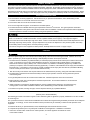
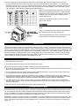
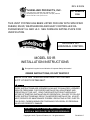
REV. B 02/06
TJERNLUND PRODUCTS, INC.
1601 Ninth Street • White Bear Lake, MN 55110-6794
PHONE (800) 255-4208 • (651) 426-2993 • FAX (651) 426-9547
Visit our web site • www.tjernlund.com
UC1 VERSION
X.06
THIS VENT SYSTEM HAS BEEN LISTED FOR USE WITH SPECIFIED
RHEEM, RUUD, WEATHERKING AND HEAT CONTROLLER OIL
FURNACES BY UL AND ULC. SEE FURNACE RATING PLATE FOR
VERIFICATION.
INCLUDES UC1
UNIVERSAL CONTROL
MODEL SS1R
INSTALLATION INSTRUCTIONS
!
Recognize this symbol as an indication of important Safety Information!
OWNER INSTRUCTIONS, DO NOT DESTROY
NOTE: FLUE GAS TEMPERATURES MUST NOT EXCEED
575oF AT VENT SYSTEM INLET.
THESE INSTRUCTIONS ARE INTENDED AS AN AID TO QUALIFIED, LICENSED
SERVICE PERSONNEL FOR PROPER INSTALLATION, ADJUSTMENT AND
OPERATION OF THIS UNIT. READ THESE INSTRUCTIONS THOROUGHLY
BEFORE ATTEMPTING INSTALLATION OR OPERATION. FAILURE TO FOLLOW
THESE INSTRUCTIONS MAY RESULT IN IMPROPER INSTALLATION, ADJUSTMENT, SERVICE OR MAINTENANCE POSSIBLY RESULTING IN FIRE, ELECTRICAL SHOCK, CARBON MONOXIDE POISONING, EXPLOSION, OR PERSONAL
INJURY OR PROPERTY DAMAGE.
DO NOT DESTROY. PLEASE READ CAREFULLY AND
KEEP IN A SAFE PLACE FOR FUTURE REFERENCE.
Copyright © 2006, Tjernlund Products, Inc. All rights reserved
P/N 8504117
TABLE OF CONTENTS
Page (s)
Description and Specifications ........................................................................................................................................1
Installation Restrictions .................................................................................................................................................2
Cautions .........................................................................................................................................................................2
Safety Inspection of a Previously Used Appliance .....................................................................................................2, 3
SS1R Terminology .........................................................................................................................................................3
LED Status / Fault Indicators and Fault Retrieval from Memory .....................................................................................3
SS1R With Integral UC1 Universal Control Board Features ..........................................................................................4
Pre / Post-Purge & Pre-Cycle Prover Status Check Settings......................................................................................4, 5
Vent Hood Termination Clearances For U.S. Installations ..........................................................................................5, 6
Vent Hood Termination Clearances For Canadian Installations..................................................................................6, 7
Installation
Tools Required .................................................................................................................................................7
Vent Hood Terminus Installation ..................................................................................................................7, 8
Installation of Rain Shield .................................................................................................................................8
Plenum Installation .......................................................................................................................................8, 9
Installation of Plenum Wall Support Bracket .....................................................................................................9
Installation of Vent Pipe ..............................................................................................................................9, 10
Electrical Wiring
Wiring Restrictions ..........................................................................................................................................11
Installation of Oil Solenoid Valve on "D" & “F” Series oil furnaces (-OBD, F-XXX, -OPD, F-XXX and etc.) ...11
Field Wiring Connections & Sequence of Operation.....................................................................11, 12, 13, 14
Selection of Proper Bleed Orifice & Draft Adjustment ............................................................................................14, 15
Combustion Air .............................................................................................................................................................15
System Operation Check Out .......................................................................................................................................15
Troubleshooting Oil Odors.......................................................................................................................................15, 16
Troubleshooting Electrical Problems .................................................................................................................16, 17, 18
Maintenance ..................................................................................................................................................................18
Removal & Replacement of Motor/Wheel ......................................................................................................18
Warranty ........................................................................................................................................................................19
Mounting Templates
Template B Motor Notch ................................................................................................................................20
Template A Vent Hood Terminus....................................................................................................................21
SideShot® is a registered trademark of Tjernlund Products, Inc. for their Model SS1R Vent System.
DESCRIPTION
The SS1R is a mechanical vent system designed and listed for use with specified Rheem, Ruud, Weatherking and Heat Controller oil
fired furnaces. The SS1R automatically vents the flue gases away from the oil furnace to the outdoors. By combining outside air
with high-tech insulation and maintaining required clearances, surrounding combustible materials remain at safe temperatures. A
factory post-purge time is set at 2 minutes and is adjustable up to 16 minutes, see “Pre / Post-purge Settings” on page 4. The
SS1R features a safety system consisting of the integral UC1 Universal Control, a Fan Proving Switch and a High Limit temperature control. These devices monitor the SS1R’s performance and will interrupt the main burner if a venting malfunction is detected.
APPLICATION TABLE
Verify that the total BTU/hr. input of the heating appliance(s) fall
within the proper category listed below. All BTU/hr. capacity ranges
are based on a maximum of 10 linear feet of vent pipe with no more
than 3 - 900 elbows. (Two 450 elbows are equivalent to one 900 elbow)
SPECIFICATIONS
Motor: 115/1/60, 3300 RPM, 212 watts, 2.28 FLA
Fan Proving Switch: Non-adjustable set point of -.04" W.C.
High Limit: Manual reset, N/C contacts, open at 135oF + 10oF.
UC1 Universal Control: See UC1 Universal Control Board Features on page 4.
Pre-Purge: Options (0, 5, 20, 35 seconds); Post-Purge: Factory set at 2 minutes, Options (0, 30 seconds or 1, 2, 4, 8, 16 minutes).
See page 4 for Pre / Post-purge options.
Oil Solenoid Valve: ON - Off control of oil flow to burner; 3-8 second valve opening delay; 120 VAC, .115 Amps, 13.8 VA
A
B
C
27 3/8" 16 1/2" 12 1/4"
Rough-In
8” Height
8 3/8” Width
D
8"
G
FRONT VIEW
7 3/4"
SIDE VIEW
1
E
F
13 3/4" 15 1/8"
H
I
14 3/4" 23 1/4"
GENERAL INFORMATION
These units have been factory tested and rated in accordance with AMCA standard 210, Test Code for Air Moving Devices and
also rated in accordance with the following Canadian Standards: CAN/CSA - B140.0-M87 General Requirements For Oil Burning
Equipment; CAN/CSA - B139-M91 Installation Code For Oil Burning Equipment; CAN3 - B255-M81 Mechanical Flue - Gas Exhausters.
Each SS1R is electrically factory line tested before shipment. After opening carton, inspect thoroughly for hidden damage. Wheel
should rotate freely. If any damage is found notify freight carrier and your distributor immediately and file a concealed damage claim.
INSTALLATION RESTRICTIONS
1. Do not install on condensing appliances. Use this device only on specified oil fired Rheem, Ruud, Weatherking & Heat
Controller furnaces. Do not use with more than one furnace.
2. A barometric draft control must be used with the SS1R.
3. Do not use single wall vent pipe in unconditioned or unheated spaces.
4. The SS1R shall not be installed where flue gas temperatures exceed 575oF at its inlet. Flue gas temperature verification:
Measure temperature of flue gases at the inlet to the SS1R at time of installation. Measure the temperature after the appliance
and SS1R operate for at least 15 minutes, allowing flue gas temperature to stabilize.
Improper installation, adjustment, alterations, service or maintenance can cause injury, property damage or death. Refer to this
manual. For assistance or additional information consult a qualified installer, service agency or the equipment supplier.
Do not exceed the recommended input range of the SS1R. Under no circumstances shall the minimum draft adjustment be used
for the larger input range of this product. Improper adjustment may result in the dispersion of flue products (carbon monoxide)
into the building interior causing carbon monoxide poisoning or death.
If oil nozzle is changed or other equipment is added perform “Draft Adjustment Procedure” on page 14 again.
CAUTIONS
Disconnect power supply from the oil furnace when making wiring connections and servicing the SS1R. Failure to do so may
result in personal injury and/or equipment damage. LED #6 (RED) should be off with power removed.
1. The SS1R must be installed by a qualified installer (an individual properly licensed and/or trained) in accordance with all local
codes. In the absence of local codes, USA installations should be in accordance with the latest editions of the applicable
National Fire Protection Agency (NFPA) code. These are NFPA 31 (Installation of Oil-Burning Equipment), and NFPA 211
(Chimneys, Fireplaces, Vents and Solid Fuel burning Appliances). In addition, USA installations must comply with the National
Electrical Code. In the absence of local codes in Canada, installations must comply with CSA Std 139 (The National Building
Code of Canada) and CSA Std 22.1 (The Canadian Electrical Code).
2. Plan the vent layout so that the code required clearances are maintained from plumbing, wiring and combustible materials.
3. The SS1R motor shaft must be mounted horizontally to ensure proper operation of the Fan Proving Switch and prevent
motor bearing wear.
4. Flue gas temperatures must not exceed 575oF at SS1R inlet. Ambient temperature must not exceed 104oF.
5. Make certain the power source is adequate for the SS1R requirements. Do not add the SS1R to a circuit where the
total electrical load is unknown.
6. "Safety Inspection of a Previously installed Appliance" must be completed when replacing a conventional chimney
venting system or when SS1R is installed on Rheem, Ruud, Weatherking or Heat Controller oil fired furnaces.
7. The SS1R vent system, including vent pipe, must be inspected annually by a qualified individual.
*SAFETY INSPECTION OF A PREVIOUSLY INSTALLED OIL APPLIANCE
(Perform prior to SS1R installation)
The following procedure is intended as a guide to aid in determining that an appliance is properly installed and is in safe condition
for continuing use.
This procedure is based on central furnace installations and it should be recognized that generalized procedures cannot anticipate
all situations. Accordingly, in some cases deviation from this procedure may be necessary to determine safe operation of the
equipment.
a. Install the SS1R only on specified Rheem, Ruud, Weatherking & Heat Controller oil fired furnaces.
b. Complete this procedure prior to any attempt at modifications of the appliance or installation of the SS1R.
c. If there is a condition which could result in unsafe operation, shut off the appliance and advise the owner
of the unsafe condition.
2
The following steps should be followed in making the safety inspection:
1. Visually inspect the venting system and determine there is no blockage or restriction, leakage, corrosion or other deficiencies
which could cause an unsafe condition.
2. Inspect burner and primary control for proper operation.
3. Inspect heat exchanger for cracks, openings or excessive corrosion. Check both the limit control and fan control for proper operation.
SS1R TERMINOLOGY
LED STATUS & FAULT INDICATORS
LED INDICATOR LIGHTS
LED #1 (Amber) Appliance call for heat.
LED #2 (Blue)
Safety circuit through P1 & P2 (SS1R Limit & Fan Prover). Indicates SS1R Limit & Prover are closed during run cycle.
Oil solenoid valve is energized with Interlock Relay contact closure from terminal 3 to 4.
LED #3 (Green) Power switched to SS1R motor & burner motor from L to MTR & M.
LED #4 (Red)
Status / Fault indicator.
LED #5 (Red)
Used as a status indicator.
LED #6 (Red)
115 VAC power supplied to board.
LED STATUS INDICATORS
LED #4 & #5 (Red) Flashing Alternately
= Venter in Pre-purge. (Pre-Purge options 0, 5, 20, 35 seconds)
LED #4 & #5 (Red) Flashing in Unison
= Venter in Post-Purge. (Post-Purge options 0, 30 seconds or 1, 2, 4, 8, 16 minutes)
LED #4 Flashing Continuously*
= Fan Prover opened for more than 10 seconds during burner cycle.
(Venter will run for 10 minutes, attempting to make Fan Prover)
LED #5 (Red) Flashing Intermittently
= With no call for heat, flashes 3 seconds on / 3 seconds off if microcontroller is working properly.
LED FAULT INDICATORS
Fault conditions are indicated by counting the number of times LED #4 (Red) flashes.
LED #4 Flashes 2 Times
Fan Prover was in electrically closed position prior to venter operation.
LED #4 Flashes 3 Times*
Fan Prover does not close within 60 seconds after call for heat.
LED #4 Flashes 4 Times*
Fan Prover did not re-close after 10 minutes of Venter operation.
LED #4 Flashes 5 Times*
Fan Prover opened for more than 10 seconds during burner cycle but closed within 10 minutes.
* Investigate causes of Fan Prover not making, i.e; Firing burner at capacities or temperatures exceeding Venter limits, excessive
vent pipe runs, high winds, plugged / kinked Fan Prover sensing tube or a faulty Fan Prover. Reset SS1R High Limit. If Limit
was tripped and SS1R fires, investigate cause of high heat.
IMPORTANT: Fault codes will automatically be displayed after a fault condition occurs. If the call for heat interlock signal
or 115 VAC power is removed, the UC1 board will reset and the fault will be stored in memory instead of displayed. Any
tripped
and
fires,
cause of high heat.
new
fault
willSS1R
replace
anyinvestigate
previous fault.
CHECKING MEMORY FOR LAST FAULT CODE
IMPORTANT: Prior to accessing the fault code memory, note the settings of the dip switches so that they can be returned to their
original Pre / Post-Purge positions. When power is supplied to the UC1 use caution when moving dip switches.
The last fault code can be retrieved at any time by setting all dip switches 1-8 to the up, or “on” position. The last fault code, or
lack there of, will be indicated by counting the number of times LED #4 flashes. By moving any of the dip switches back to their
original position, the fault code will be cleared. NOTE: The UC1 board must have its 115 VAC power supply present when any of
the (1-8) dip switches are moved back to their original position for the fault code to clear.
3
SS1R WITH INTEGRAL UC1 UNIVERSAL CONTROL BOARD FEATURES
C, GND, F AUXILIARY DEVICE
COMMUNICATION TERMINALS
2 mA @ 5VDC. For Tjernlund MAC1E or
MAC4E auxiliary devices. SEE WARNING # 1.
P1 - P2 SAFETY CIRCUIT
TERMINALS
1 mA @ 5VDC.
SEE WARNING # 1.
DIP SWITCH SETTINGS
Pre-Purge (1-2)
Post-Purge (3-8)
Prover status check (9)
See “Pre / Post Purge &
Prover Status Check Dip
Switch Settings”.
P1 P2
LED 6 (RED) POWER LED
(1
LED STATUS LIGHTS
See “LED Status & Fault
Indicator Section” for details.
APPLIANCE CALL
VOLTAGE SELECTION
IMPORTANT
Place RED voltage jumper in
proper location based on
appliance call interlock voltage. SEE WARNING # 2.
DRY
# 3.
I
APPLIANCE INTERLOCK
RELAY
1 HP MAX LOAD across
terminals 3 & 4.
APPLIANCE
INTERLOCK
RELAY
VENTER
MOTOR
RELAY
J1
J2
XL
VENTER MOTOR RELAY
1 HP MAX LOAD from
terminals L to MTR & M.
XL / XN AUXILIARY DEVICE
POWER TERMINALS
115 VAC - Maximum of 0.15 Amps.
Only connect to Tjernlund auxiliary devices.
SEE WARNING # 1.
115 V
XN
N
A B 1 2 3 4 L N
APPLIANCE INTERLOCK
TERMINAL BLOCK (A-B, 1-4)
A - B - Dry Contact call. 3 mA @ 5VDC.
SEE WARNING # 1.
1 - 24 or 115 VAC intercepted call.
IMPORTANT: RED voltage jumper must
match intercepted call voltage.
2 - 24V common or 115V Neutral.
3 - Common terminal to appliance relay contacts. IMPORTANT: J1-J2 jumper routes
call voltage at terminal 1 to 3. Remove
J1-J2 jumper if a different voltage source is
provided to terminal 3.
4 - Normally open terminal of appliance relay.
Will be energized from terminal 3 if safety
circuit is “proven”.
# 1.
# 2.
9)
LED 1 (AMBER)
LED 2 (BLUE)
LED 3 (GREEN)
LED 4 (RED)
LED 5 (RED)
24 V
J1- J2 CALL
JUMPER
Used when the call signal is
used as the “proven” return
signal to the appliance. See
wiring section for details.
C GND F
M
MTR
L / N - 115 VAC POWER
SUPPLY BLOCK
115 VAC / 50-60 Hz
Circuit protection provided by installer.
SEE WARNING # 3.
MTR & M LOAD TERMINALS
FROM VENTER MOTOR RELAY
Used to drive SS1R Motor & Burner Motor.
1 HP MAX LOAD across terminals MTR & M / N.
Power supplied by board. Do not supply power to this area or control damage may result.
Do not supply power to the appliance interlock block with the call selector in the “DRY” position.
Control damage may result if power is supplied.
Circuit protection must be provided by the installer. 16 Amps is the maximum current allowed for this device at terminal L.VETI
A
A 15 Amp circuit breaker is recommended.VETI
PRE / POST PURGE AND PROVER STATUS CHECK DIP SWITCH SETTINGS
Remove power to SS1R and heating equipment when installing, servicing or changing dip switch settings. Failure to do so may result in
personal injury and/or equipment damage. LED #6 (RED) should not be on if 115 VAC supply power is removed from the control.
Pre-purge
Used for longer vent runs to get draft fully established throughout the vent system prior to burner ignition. Also beneficial for negative pressure prone environments. IMPORTANT: Nuisance equipment lockouts may occur if our pre-purge is running in conjunction with and is longer than any equipment timing circuit. Pre-purge settings must be shorter than burner control lockout time
unless wired prior to burner control timing circuit (i.e. aquastat / thermostat).
Post-purge
A Venter post-purge has been factory set at 2 minutes. Confirm that dip switch #5 is in the up or "on" position. Oil fired equipment
requires that the post-purge be long enough to eliminate post cycle nozzle drip odor. A longer post-purge may be necessary for
longer vent runs or high heat retention, refractory lined combustion chambers.
4
Pre-Cycle
Prover Status
Check Deactivated
DIP SWITCH NUMBERING
Pre-Purge
Post-Purge
LED 6 RED
POWER LED
ON
1
ON
1 2
3 4 5 6
7 8
9
LED 1 AMBER
LED 2 BLUE
LED 3 GREEN
LED 4 RED
LED 5 RED
PRE-PURGE SETTINGS (SEE “PRE-PURGE”, ON PAGE 4 PRIOR TO SETTING)
ON
1 2
0 Seconds
1 2
5 Seconds
1 2
20 Seconds
9
1 2
35 Seconds
POST-PURGE SETTINGS (SEE “POST-PURGE”, ON PAGE 4 PRIOR TO SETTING)
ON
ON
3 4 5 6 7 8
0 Seconds
3 4 5 6 7 8
30 Seconds
3 4 5 6 7 8
1 Minute
3 4 5 6 7 8
4 Minutes
3 4 5 6 7 8
8 Minutes
3 4 5 6 7 8
16 Minutes
3 4 5 6 7 8
2 Minutes
P1 & P2 PRE-CYCLE FAN PROVER STATUS CHECK
Pre-Cycle
Prover Status
Check Deactivated
9
The Pre-Cycle Prover Status Check is deactivated from the factory on the SS1R. Because of the
low set point of the SS1R Fan Prover (as low as .03" w.c.) cross winds may cause the Fan Prover
to close prior to a call for heat. Activating the Prover Status Check on the SS1R may cause
nuisance lockouts.
PLENUM AND VENT HOOD CLEARANCE FROM COMBUSTIBLES
With an inlet flue gas temperature of 575oF or below, the SS1R has been Listed for the following clearances from combustible materials:
IMPORTANT
Vent Hood and top of Plenum: Zero Clearance
Plenum front and sides: 1/2 inch
Plenum rear: 3 inches
VENT HOOD TERMINATION CLEAOR
TERMINATION CLEARANCES FOR U.S. INSTALLATIONS
Install the SS1R according to the requirements of the National Fire Protection Association #31, #54 and #211 as follows,
(See Diagram A):
• The exit terminals of mechanical draft systems shall not be less than 7 feet above grade when located adjacent to public walkways.
• A venting system shall terminate at least 3 feet above any forced air inlet located within 10 feet.
• The venting system shall terminate at least 4 feet below, 4 feet horizontally from or 1 foot above any door, window or gravity air
inlet into any building.
• The bottom of the vent terminal shall be located at least 12 inches above grade.
• Arrange the exit terminal so that the flue gases are not directed so as to jeopardize people, overheat combustible structures or
enter buildings.
• Not to be less than 2 feet from an adjacent building.
The SS1R is also Listed to terminate a minimum of 12" below, above or horizontally from a soffit, deck or adjacent sidewall.
5
It is not recommended for the SS1R to be terminated on a wall that faces the direction of
the prevailing winds. Backdrafts by severe winds can cause oil odors to remain in the
structure and/or interrupt heating equipment operation.
DIAGRAM A
TERMINATION CLEARANCES FOR CANADIAN INSTALLATIONS
The SS1R has been CSA Listed according to the requirements of “Mechanical Flue-Gas Exhausters” CSA Std B255-M81 and the
“Installation code for Oil burning Equipment” CSA Std B139-M91. (See Diagram. A1)
• A venting system shall not terminate underneath a veranda, porch, or deck, or above a paved sidewalk or a paved driveway
that is located between two buildings, and that serves both buildings.
• The exit terminals of mechanical draft systems shall not be less than 2.13m (7ft) above grade when located adjacent to a paved
sidewalk or driveway.
• A venting system shall not direct flue gases towards brickwork, siding, or other construction, in such a manner that may cause
damage from heat or condensate from the flue gases.
• A venting system shall not direct flue gases so as to jeopardize people, overheat combustible structures, or enter buildings.
A venting system shall not terminate within 1.8 m (6ft) of the following:
• A window, door or mechanical air supply inlet of any building, including soffit openings
• A gas service regulator vent outlet
• A combustion air inlet
• A property line
• A direction facing combustible materials or openings of surrounding buildings
A venting system shall not terminate within 1m (3ft) of the following:
• Above a gas meter/regulator assembly within 1m (3ft) horizontally of the vertical centreline of the regulator
• A oil tank or an oil tankfill inlet
• The inside corner of an L-shaped structure
A venting system shall not terminate within .3m (1ft) of the following:
• Above grade level or any surface that may support snow, ice, or debris
6
It is not recommended for the SS1R to be terminated on a wall that faces the direction of
the prevailing winds. Backdrafts by severe winds can cause oil odors to remain in the
structure and/or interrupt heating equipment operation.
DIAGRAM A1
INSTALLATION
Tools required:
• Reciprocating Saw
• Drill and 1/8", 1/4", 1/2" Bits, 1” hole saw
• Blade Screwdriver
• Wire Cutter/Stripper
• Tube Cutter
Materials required:
• 1/2", 7/16",5/8" Wrench
• 1/4" Masonry Drill Bit
• 1/4", 5/16”, 11/32" Nut Driver/Socket
• Hammer
• Vent Pipe
• Wire
• Wire Nuts
• 1” Strain Reliefs
• 1” Anti-Short Bushings
• Electrical Conduit
INSTALLING VENT HOOD TERMINUS
1. a) Fold template A along dashed line and attach in between the floor joists ensuring that it is
snug against the sill plate and right hand floor joist. Follow same procedure if floor trusses
are used, (See Diagram B).
b) If the SS1R is not being installed between floor joists, attach the template to the wall it will be
exiting ensuring it is level.
2. Using 1/2" bit, drill pilot holes noted on each side of the template from inside through rim-joist,
wall board, siding, etc., keeping drill bit perpendicular to the wall. 1/2" bit must be long enough
to penetrate through exterior.
3. Remove template from rim-joist and attach to building exterior, aligning pilot hole markings on
template with holes previously created in Step #2.
4. Drill the four corner holes noted on the template through the building exterior. Remove the
template and mark lines from the outside edge of the holes drilled, forming a rectangle.
5. Using reciprocating saw and appropriate blade, cut a rectangular opening through the rim joist, wall board, siding, etc., on the lines marked in
step 4. The rectangular opening should be no larger than 8-3/8" in width
by 8" in height, (See Diagram C).
6. Knock out block material exposing rectangular opening through the wall.
7. Apply two beads of exterior rated caulk approximately 3/8" in width at
the seam of the outermost casing of the Vent Hood and the inner
flange of the Vent Hood Terminus, (See Diagram D).
7
DIAGRAM C
DIAGRAM B
DIAGRAM D
DIAGRAM E
OUTERMOST CASING
BUILDING
EXTERIOR
RAINSHIELD
(INSTALL BETWEEN BUILDING
EXTERIOR AND INNER FLANGE)
INNER FLANGE OF VENT HOOD TERMINUS
8. Slide Vent Hood Terminus through the wall while taking care
installing the rain shield as shown, (See Diagram E). The nuts
located on the Vent Hood outermost casing should be facing up
when sliding it through the wall. Mount Vent Hood to the exterior
using four #8 x 3" wood screws & spacers provided, (See Diagram E).
Wall anchors are provided for installation into masonry wall.
DIAGRAM F
9. Connect the Plenum to the Vent Hood Terminus of the SS1R
following the steps on pages 8, 9.
10. After the SS1R is completely installed, apply a bead of exterior
rated caulk between the Vent Hood Terminus inner
flange and the exterior of the building, (See Diagram F).
INSTALLING PLENUM
Depending on building construction, it may be
necessary to notch out a section of the floor
joist to provide proper clearance for the SS1R
motor, (See Diagram G).
DIAGRAM G
IMPORTANT: DO NOT NOTCH ANY
OTHER JOISTS OTHER THAN THOSE
OUTLINED IN THESE INSTRUCTIONS
1. Attach Template B to the floor joist that is to
be notched, aligning the sight line noted on
the template with the end or the outside
casing of the Vent Hood Terminus.
2. Cut out notch on line shown on the template.
NOTCH BRACING
It is recommended and local codes may dictate that the joist be reinforced as outlined below. Bracing of the rim joist is not necessary.
1. Cut two 2 x 4 pieces of wood 28 inches in length.
2. Center both pieces on each side of the floor joist above the notch and drive 8 16D or larger nails into each piece, (See Diag. H).
DIAGRAM H
CONNECTING THE PLENUM TO THE VENT HOOD TERMINUS
NOTES: Cut any nails which are protruding downward from the subfloor that may come in contact with the SS1R. Place both slip
joint drivers in your pocket before continuing.
8
Minimum clearances from the Plenum to any combustible materials must be maintained as listed on page 5. Failure to do so can
cause a fire or explosion resulting in property damage, personal injury or death.
Note: Blower - Motor/Wheel assembly can be removed to make
Plenum section easier & lighter to install. Refer to Removal
and Replacement of Motor/Wheel Assembly, Page 18.
DIAGRAM I
1. Connect the Plenum to the Vent Hood by aligning both grooves
on the bottom of Plenum with both grooves on the bottom of the
Vent Hood. The Plenum is designed to slide into the Vent
Hood, (See Diagram I).
2. Gently slide the Plenum into the Vent Hood until the slip joint
guides located on each side of the Plenum are in contact with
each other.
3. Slide the slip joint drivers from the bottom upward over the the slip joint guides as far as possible by hand. A hammer may be
used to tap the slip joint drivers to their final position. Start the slip joint drivers on the slip joint guides with the embossed end
facing down. Do not force slip joints past embossing.
INSTALLATION OF WALL SUPPORT BRACKET
1. To prevent damage to the SS1R, temporarily support the bottom of the plenum (prop on ladder) while assembling the wall
support bracket. Assemble the wall support bracket as shown, (See Diagram J).
2. Using the prepunched holes, adjust the wall support bracket so that a slight pitch is maintained for water drainage, (See
Diagram J).
3. Use the prepunched holes on the wall bracket as a template to mark holes to be drilled into the side wall for mounting screws.
4. a)
b)
If installing the bracket into a wood wall, drill 2 pilot holes at each point established in step 3 with a 1/8" drill bit
approximately 1" deep and install the screws provided to secure the bracket to the wall.
If installing the bracket into a masonry wall, drill 2 holes at each point established in step 3 with a 1/4" masonry drill bit
approximately 1" deep. Tap the masonry anchors into the holes drilled in step 4. Screw the wall bracket onto the wall.
5. Connect the other end of wall support bracket to the stud on the plenum using the supplied 1/4"-20 keps nut, (See Diagram J).
DIAGRAM J
IMPORTANT:
Adjust SS1R mounting
bracket for a slight downward
pitch towards exit terminal.
INSTALLATION OF VENT PIPE
Single wall vent pipe is not allowed in an unconditioned or unheated space. When Installing the SS1R vent system, a barometric
draft damper control must be used. Install the barometric draft damper as close as is practical to the SS1R with the center line of
the barometric damper not closer than 10 inches to the SS1R inlet. Always install the draft damper in a 6” section of pipe. The
general venting configurations are shown in diagram K. The SS1R vent system is designed to accept 6” single wall, type”L” or
type “A” vent pipe. When installing the vent system, it will be necessary to use the tapered reducers or increasers as shown.
Determine which inlet of the SS1R will allow for the least amount of elbows to the furnace. When using single wall pipe, a minimum clearance of 18” must be maintained between the vent pipe and combustible materials and the vent pipe must be exposed to
view for its entire length. If this clearance cannot be maintained, type “L” or type “A” vent may be used according to its listing and
vent pipe manufacturer’s instructions.
A maximum of 10 linear feet of vent may be used to connect the SS1R to the furnace. No more than three 900 elbows may be
used (two 450 elbows will be considered equivalent to one 900 elbow).
9
The SS1R vent system is shipped from the factory with the plug connected to the rear and the vent pipe inlet collar connected at
the bottom. If using the bottom inlet, see “Vent Pipe Clamp Assembly” at bottom of page. If the installation requires the use of the
rear inlet, see “Vent Pipe Inlet Collar Conversation” to move the vent pipe inlet collar from the bottom to the rear.
DIAGRAM K
IMPORTANT: Oil installations
must have a barometric draft
control.
VENT PIPE INLET COLLAR CONVERSION
1. Remove the plug from rear inlet port
by unfastening the 6 nuts that secure it
to the Plenum. Keep the plug & nuts
for later use.
DIAGRAM L
DIAGRAM M
2. Remove the sensing tube from the
Fan Proving Switch by loosening the
plastic compression fitting.
3. Remove the vent pipe inlet collar from
the bottom port by unfastening the
6 nuts that secure it to the plenum.
Keep the nuts for later use.
4. Using a tube cutter, cut the sensing
tube 2" from the elbow directed at the
vent pipe inlet collar, (See Diagram L).
Discard the cut off section of metal tube.
5. Attach the vent pipe inlet collar to the rear inlet port making sure that the sensing tube is orientated as shown, (See Diagram M).
NOTE: Alignment marks on the inlet collar and plenum casing must match.
0
6. Attach 90 compression fitting to the short tube on the inlet collar.
7. Using the "soft" aluminum tubing, connect the Fan Proving Switch to the inlet collar. Take care not to crimp the tubing.
8. Install the plug removed in step 1 over the bottom inlet port, tightening securely.
VENT PIPE CLAMP ASSEMBLY
NOTE: The following diagrams show the use of the rear inlet. The same steps will apply if using the bottom inlet.
1. Attach the three vent pipe clamps to the inlet collar, (See Diagram N).
2. Bend each vent pipe clamp so it conforms to the outside diameter of the vent pipe being used, (See Diagram O)
3. Route the adjustable clamp through the openings at the opposite end of the legs.
4. Slide the vent pipe over the inlet collar of the SS1R.
5. Tighten the adjustable clamp around the vent pipe, (See Diagram O).
DIAGRAM N
DIAGRAM O
10
ELECTRICAL WIRING OF SS1R ON OIL EQUIPMENT
All wiring from the SS1R to the appliance must be appropriate Class 1 wiring as follows: installed in rigid metal conduit, intermediate metal conduit, rigid non-metallic conduit, electrical metallic tubing, Type MI Cable, Type MC Cable, or be otherwise
suitably protected from physical damage.
PREPARATION FOR SYSTEM WIRING
MAKE SURE ALL POWER IS DISCONNECTED FROM THE FURNACE BEFORE ATTEMPTING TO INSTALL THE SS1R.
FAILURE TO DO SO CAN CAUSE ELECTRICAL SHOCK RESULTING IN PERSONAL INJURY OR DEATH.
INSTALLATION OF OIL SOLENOID VALVE
On "D" series oil furnaces (-OBD-XXX, -OPD-XXX and etc.) (DIAGRAM P)
1. Apply pipe sealant to the elbows and attach the
elbows to the valve in the positions shown.
DIAGRAM P
2. Place the ½" chase nipple through the cad cell
housing with the 7/8" grounding lock-washer on
the outside of the housing as shown.
3. Thread the chase nipple into the valve passing the
wires of the valve through the chase nipple.
4. Connect one 8” Tube Assy. from the pump to the
Valve and the remaining 8” Tube Assy. from the
Valve to the Nozzle Line paying attention to the
direction of flow as shown.
5. Thread wires (2) from solenoid valve to cad cell
housing of burner and out through the opposite
side of the burner on to the exit hole drilled in the
furnace wall.
On "F" series oil furnaces (-OBF-XXX, -OPF-XXX
and etc.)
The solenoid valve supplied with the SS1R kit will not
be installed on Rheem/Ruud/Weatherking -OBF-XXX
or -OPF-XXX models. These model furnaces come
equipped with a solenoid valve already mounted to
the burner. The valve is controlled by the furnace primary control. This existing solenoid will be wired into
the SS1R UC1 control. See Diagram R for wiring schematic.
MAKE SURE THAT ALL POWER IS DISCONNECTED AND TURNED OFF COMPLETELY BEFORE PROCEEDING TO
INSTALL THE SS1R POWER VENTER. FAILURE TO DO SO COULD RESULT IN PERSONAL INJURY OR DEATH.
THE FOLLOWING INSTRUCTIONS PERTAIN ONLY TO RHEEM, RUUD, OR WEATHERKING "D" (-OBD-XXX, -OPD-XXX and
etc.) and "F" (-OBF-XXX, -OPF-XXX and etc.) SERIES OIL BURNING FURNACES.
1. All wiring from the SS1R to the oil furnace must be appropriate Class 1 wiring as follows: installed in a rigid metal conduit,
intermediate metal conduit, rigid non-metal conduit, electrical metallic tubing, Type MI Cable, Type MC Cable, or be otherwise
suitably protected from physical damage while complying with the latest revision of the National Electric Code.
2. Always route wires neatly around the front of the burner and wire tie them to the burner in a way so that the wires will never
touch a hot part of the furnace (such as the center panel).
3. Remove the screws that secure the primary control to the junction box.
On "D" series oil furnaces (-OBD-XXX, -OPD-XXX and etc.), the primary control module (Honeywell R8184-M) is located on
the main junction box mounted to the interior wall of the furnace.
On "F" series oil furnaces (-OBF-XXX, -OPF-XXX and etc.), the primary control module (Honeywell 7184B) and junction box
is mounted directly to the oil burner assembly.
4. For "D" series oil furnaces (-OBD-XXX, -OPD-XXX and etc.): Remove the primary control from the main junction box and
push the wires inside to the side so that the holes on the back of the junction box can be seen. Once these holes are located,
choose one of these holes and trace its pattern onto the furnace wall. Once the hole is traced, remove the main junction
box/primary control assembly from the wall of the furnace and drill out the newly traced hole with a 1" drill. Use caution when
drilling into the furnace so existing wiring and components are not damaged. The four wires connecting the Rheem, Ruud or
Weatherking oil-fired furnace to the SS1R power venter must be routed through this new hole. When the hole is complete,
install a 1" diameter bushing. If electrical conduit is not going to be used, then a mechanical strain relief must be used where
wires pass through the furnace wall. Next, replace the junction box to the wall of the furnace, but leave the primary control detached.
11
For "F" series oil furnaces (-OBF-XXX, -OPF-XXX & etc.): Drill a 1" diameter hole into the junction box side of the furnace
wall, allowing for adequate clearance from electrical components. (Do not drill the hole at or near the junction box.) Use caution
when drilling into the furnace so existing wiring and components are not damaged. The five wires connecting the Rheem, Ruud
or Weatherking oil-fired furnace to the SS1R power venter must be routed through this new hole. When the hole is complete,
install a 1" diameter bushing. Some wires will route to the burner junction box and some will route to the main junction box on
the furnace wall. If electrical conduit is not going to be used to the junction boxes, then a mechanical strain relief must be used
where wires pass into the junction boxes (Note: There may be additional room in the existing strain relief(s) of the junction
boxes to add additional wires. Check the specifications for the strain relief.).
5. For "D"(-OBD-XXX, -OPD-XXX and etc.) series oil furnaces, remove the wire-nuts which secure the Orange to Black wires
(burner control) and White wires (line neutral) of the primary control (see Diagram Q).
A.
In addition to the L1, Neutral and ground that must be supplied to the SS1R UC1 control board, four wires are to be
installed from the oil furnace to the SS1R Side Wall Vent System. Refer to Diagram Q and instructions below for wiring.
B.
Attach L1 (115V) and Neutral wires from a nominal 115VAC power source to L & N on the UC1 control board. This power
should be routed through a disconnect so that power to the SS1R can be turned off remotely if necessary. Additionally, all
wire should be run through the appropriate conduit per NEC standards as noted in step 1.
C.
A ground wire will need to be installed between the system ground and the grounding lug in SS1R electrical box.
D.
A neutral wire will need to be installed from the oil furnace line neutral to the terminal labeled "2" on the UC1 control
board. Note: The existing wire nut (which connects all the line neutrals together) is full and a new wire cannot be added
to it. A new (larger) wire-nut will have to be installed and this will require that the neutral wire is cut and stripped.
E.
Route a wire to connect the orange lead on the primary furnace control to the UC1 control board terminal labeled "1".
F.
Last, route a wire between the Beckett burner motor and ignition transformer to the UC1 control board terminal labeled "M".
G.
The RED Voltage Jumper on UC1 board in SS1R must be in the 115V position.
FIELD WIRING TO RHEEM, RUUD, OR WEATHERKING -OBD-XXX & OPD-XXX MODEL OIL BURNING FURNACES
DIAGRAM Q
ORANGE
PRIMARY CONTROL
IMPORTANT:
RED JUMPER POSITION MUST BE THE SAME
AS APPLIANCE INTERLOCK VOLTAGE.
VIA JUNCTION BOX
TO FACTORY-WIRED
LIMIT SWITCHES
BLACK
24V
DRY
115V
WHITE
CALL
JUMPER
J2
F
F
R
W
UNIVERSAL CONTROL
C
G
J1
Y
TO FUSE
DISCONNECT
NEUTRAL
XN
SUPPLY
115 VAC
50/60 Hz
XL
OIL VALVE
GROUND
N
M
YELLOW
YELLOW
VENTER MOTOR
(FACTORY-WIRED)
MTR
GROUNDED
JUNCTION BOX
IMPORTANT:
CRIMP GROUND WIRE TO GROUNDING
SPADE TERMINAL IN ELECTRICAL BOX.
BLACK
TO BURNER
MOTOR
TO IGNITION
TRANSFMR
LEGEND:
115 VAC, FIELD-WIRED
TO FLAME
SENSOR
115 VAC, FACTORY-WIRED
B/W
LOW VOLTAGE
BECKET BURNER
D/N 9183047-5
12
6. For "F" (-OBF-XXX, -OPF-XXX and etc.) series oil furnaces: Remove a knock-out slug from the existing junction box mounted to the burner
(see Diagram R). A 7/8" diameter bushing or strain-relief must be installed in the hole formed by removing the slug.
A.
B.
In addition to L1, Neutral and ground that must be supplied to the SS1R UC1 control board, five wires are to be installed from the oil
furnace to the SS1R Side Wall Vent System. Refer to Diagram R wiring instructions below.
Attach L1 (115V) and Neutral wires from a nominal 115VAC power source to L & N on the SS1R UC1 control board. This power should
be routed through a disconnect so that power to the SS1R can be turned off remotely if necessary. Additionally, all wire should be run
through the appropriate conduit per NEC standards as noted in step 1.
C.
A ground wire will need to be supplied between the system ground and the grounding lug in the SS1R electrical box.
D.
A neutral wire will need to be installed from the oil furnace line neutral to the terminal labeled "2" on the UC1 control board.
E.
Inside the burner mounted junction box, remove the leads from the primary control terminals labeled "Burner/Motor" and "Valve".
F.
Install a field-constructed wire between the lead removed from the terminal labeled "Burner/Motor" (step E above) and the UC1 control
board terminal labeled "M". The connection to the burner motor lead will require a special male ¼" quick connect (Amp Manufacturing
part # 2-520102-2 (insulated male spade)). Do NOT cut any wires on the existing burner. Also, the wire connection to the "Burner/Motor"
lead should be made inside the burner junction box and should be covered and concealed by the primary control once it is replaced.
Install a field-constructed wire between the terminal labeled "Burner/Motor" (step E above) and the UC1 control board terminal labeled "1".
The connection to the primary control will require a female ¼" quick connect (Amp Manufacturing part # 2-520856-2).
G.
H.
Install a field-constructed wire between the lead removed from the terminal labeled "Valve" (step E above) and the UC1 control board
terminal labeled "4". The connection to the "Valve" lead will require a special male ¼" quick connect (Amp Manufacturing part #
2-520102-2 (insulated male spade)). Do NOT cut any wires on the existing burner. Also, the wire connection to the "Valve"
lead should be made inside the burner junction box and should be covered and concealed by the primary control once it is replaced.
I.
Install a field-constructed wire between the terminal labeled "Valve" (step E above) and the UC1 control board terminal labeled "3".
The connection to the primary control will require a female ¼" quick connect (Amp Manufacturing part # 2-520856-2).
J.
IMPORTANT: The Call Jumper between J1 and J2 on the UC1 board in SS1R must be removed. The RED Voltage Jumper on UC1
board must be in the 115V position.
FIELD WIRING TO RHEEM, RUUD, OR WEATHERKING -OBF-XXX & OPF-XXX MODEL OIL BURNING FURNACES
DIAGRAM R
IMPORTANT:
CALL JUMPER MUST
BE REMOVED.
13
7. For "D"(-OBD-XXX, -OPD-XXX and etc.) series oil furnaces, Replace the junction box / primary control to the wall of the
furnace in the same fashion as the original factory placement. Replace the furnace door.
For "F"(-OBF-XXX, -OPF-XXX and etc.) series oil furnaces, Replace the primary control to the junction box and replace the
junction box cover on the junction box on the wall of the furnace in the same fashion as the original factory wiring. Replace the
furnace door.
8. Return the system to normal operation by installing the furnace doors and applying power to the system. System operation
should be verified as described in the next section.
SEQUENCE OF OPERATIONS WITH SS1R POWER SIDEWALL VENTER INSTALLED ON RHEEM, RUUD,
OR WEATHERKING OIL-FIRED FURNACES.
When the thermostat calls for heat, the Honeywell burner control is closed. This causes 115 VAC to be applied to terminal #1 of
the SS1R terminal strip of the UC1 control board. The #1 contact on the terminal strip supplies 115 VAC to the "M" and "MTR"
spade connections on the SS1R control board causing the Beckett burner and the induced draft motor to start immediately upon a
thermostat heat-call. At this point, the burner is running, but the oil valve is still off, so combustion has not yet started. When the
induced draft motor gets enough speed to close the pressure switch, the switch contacts operate a relay on the control board
which then supplies power to the oil solenoid valve. At this point, combustion should take place.
Once the thermostat is satisfied, the Honeywell burner control will remove 115 VAC power from terminal #1 of the SS1R UC1 control board. As a result, the oil solenoid valve snaps closed immediately and this action causes the burner flame to extinguish
immediately. The loss of power to terminal #1 of the SS1R control board begins the post-purge period. The "M" and "MTR" terminals on the SS1R control board will remain energized with 115 VAC for the entire post-purge period. This means that both the
Beckett burner and the Induced draft motor of the SS1R will remain powered for the user-selected post purge period (although no
flame is present). No flame will be present during the post-purge period because the oil solenoid (which was turned off immediately when the heat-call ended) will prevent the oil from flowing.
jSELECTION OF PRESSURE SWITCH BLEED ORIFICE
In order for the SS1R pressure switch to function properly for the intended application, the proper bleed orifice has to be selected
as determined below.
DIAGRAM S
1. Upon installation, if the furnace input rate is 1
gallon per hour or less (140,000 BTU/hr. or less),
then the plug should be installed in the pressure
switch.
2. Upon installation, if the furnace input rate is
greater than 1 gallon per hour or 140,000 BTU/hr.,
then the #33 bleed orifice should be used.
3. Once the proper bleed orifice has been determined,
install into bleed orifice port as shown in Diagram S.
DRAFT ADJUSTMENT OIL
The SS1R Vent system will properly vent a wide range of BTU/hr. input capacities. To compensate for different burner capacities,
vent connector lengths and wind conditions it features a draft adjustment located on the outside of the Vent Hood. In general,
positioning the draft adjustment inward will cause the SS1R to operate at lowest capacity. Positioning the draft adjustment
outward will cause the SS1R to operate at highest capacity.
IMPORTANT:
The following paragraph describes the initial draft adjustment. It may be necessary to make a slight readjustment to compensate
for various conditions: wind, vent connector resistance, negative building pressure and multiple appliances.
ASHRAE lists the average design factor for wind loads in North America at 15 MPH. Refer to the Draft Adjustment Chart on page
15. We recommend that the 25 MPH category be used to allow for excursions beyond the 15 MPH average. It is not recommended for the SS1R to be terminated on a wall that faces the direction of the prevailing winds. Backdrafts by severe winds can
cause oil odors to remain in the structure and/or interrupt heating equipment operation. If the SS1R is terminated in a direction
prone to higher winds, or if higher winds are common in your geographic area, use the 40 MPH category to determine the proper
draft adjustment setting. If the draft adjustment is set at the 25 MPH category and sustained winds exceeding 25 MPH are present, the Fan Proving Switch will act to close the oil solenoid valve. Wind loads referenced are based on straight line winds
directed against the Vent Hood.
DRAFT ADJUSTMENT PROCEDURE:
1) Set the draft adjustment to the appropriate setting based on the above instructions and the Draft Adjustment Chart. Adjustment
is accomplished by loosening both nuts on each side of the Vent Hood and centering both indicators to the desired setting.
Tighten the four nuts to secure the draft adjustment at desired setting.
14
2) Place the appliance and SS1R in operation. Measure the over-fire draft. Make necessary adjustments to the primary
air intake and barometric draft control to comply with the over-fire draft requirements of the appliance. The over-fire draft
should be in a range of -.02" to -.04" W.C., with the optimum setting at -.03” W.C. If adjustments to the primary air intake and
barometric draft control do not provide the required over-fire draft, the SS1R draft adjustment must be repositioned, accordingly. Measure over-fire draft after repositioning SS1R draft adjustment.
NOTES: All draft adjustments are approximate. This chart is
to be used for initial draft adjustment only. Subsequent draft
adjustments may be required to compensate for various field
conditions: wind, vent pipe resistance, building pressure,
multiple appliances, etc.
BTU/HR input ratings assume 30% or less excess air for
flame retention burners.
Do not exceed the recommended BTU/HR input range of the
SS1R.
Under no circumstances shall the minimum draft adjustment
be used for the larger input range of this product.
Improper draft adjustment may result in the dispersion of flue
products (carbon monoxide) into the building interior.
COMBUSTION AIR
Adequate combustion air is vital for proper combustion and for safe venting. Likewise, for proper SS1R performance, adequate
combustion air must be available to the appliance. Many installers assume adequate combustion air is present, especially in older
homes. In some cases this is a false assumption, because many older homes have been made "tight" due to weatherization. Size
the combustion air opening(s) into the appliance room as outlined NFPA 31/NFPA 211. When installing a SS1R, it is usually not
necessary to supply any more combustion air than normally required when conventional venting. Common symptoms of inadequate combustion air include: Fan Proving Switch short cycling, odor present at the end of burner cycle, outside air enters the
structure through the SS1R Vent System on SS1R/Appliance off cycle.
SYSTEM OPERATION CHECK-OUT
1. Adjust thermostat to call for heat.
2. Verify that the SS1R and the burner motor both operate prior to ignition.
Allow heating equipment and SS1R to operate continuously while performing steps 3-5.
3. Close all doors and windows of the building. If heating equipment is installed in utility room or closet, close the entrance door to
this room. Close fireplace dampers.
4. Turn on all appliances in the structure that exhaust indoor air during their operation, e.g. turn on clothes dryer, exhaust fans,
such as range hoods, bathroom exhaust and whole house fans.
5. Allow SS1R and equipment to operate for at least five minutes. Tripping of the burner circuit by the Fan Prover Switch or
Limit during the five minute operation indicates an unsafe operating condition. Turn fuel supply off to appliance and DO NOT
OPERATE UNTIL UNSAFE VENTING CONDITION IS INVESTIGATED BY QUALIFIED SERVICE PERSONNEL.
6. Turn thermostat to the “off” position. Verify the SS1R and the burner operate for several minutes, without a burner flame,
before the system shuts off. This is due to the Post-purge settings of the integral UC1 Universal Control. See page 4 for Pre
and Post-Purge settings.
7. Return all windows, doors and exhaust fans to their original conditions of use.
TROUBLESHOOTING OIL ODORS
Many problems can be eliminated quite easily by having the equipment properly set up by a professional oil-heat service contractor. The sophistication of today's heating equipment and instrumentation needed for efficient operation requires proper training.
There is no substitute for the work of a qualified oil-heat service professional. All trouble shooting recommendations that follow
assume the equipment is installed and maintained by a qualified service person.
Post-purge: A post-purge is always necessary on oil installations. The factory default post-purge time period is 2 minutes. Just
as a chimney continues to draft after the burner has shut-down, the SS1R will continue to run to clear the vent system of residual
gases. The duration of the post-purge cycle is adjustable from 0 to 16 minutes. We recommend a minimum of 2 minutes postpurge on oil.
15
Draft Adjustment: The SS1R Draft Adjustment, located outdoors on the Vent Hood, has two functions: A) It allows the installer to
adjust the amount of draft in accordance with the draft adjustment chart that the SS1R must develop to vent the specific appliance,
and B) During the off-cycle, when the SS1R is off, it prevents air infiltration caused by strong winds and gusts. Air infiltration back
through the vent system will bring with it the odors from the flue gas residue on the inside of the vent pipe. When the Draft
Adjustment is at an inward setting (lower number) the Vent Hood will deflect a greater volume of wind than at a higher setting.
(REMINDER : The most significant preventer of wind-induced air infiltration is choosing a proper termination location of
the SS1R before installation, see requirements on pages 5, 6, 7 under "Vent Hood Termination Clearances.")V
Verify that the Draft Adjustment is appropriate for the BTU/hr input, as shown on the "Draft Adjustment Chart," page 15. If necessary, change setting by loosening both nuts on each side of the Vent Hood and center both indicators to the desired setting.
Tighten the four nuts to secure new Draft Adjustment.
IMPORTANT
Any adjustment to the draft setting must be followed by an over-fire draft measurement and necessary adjustments to the
primary air intake on the burner and barometric draft control. See Draft Adjustment Procedure on pages 14, 15.
Burner Adjustment: Verify that the over-fire draft matches that recommended by the heating equipment manufacturer. Adjust the
combustion efficiency and smoke characteristics to optimum levels of performance.
Combustion Air: Modern construction methods and materials have reduced natural air infiltration rates to extremely low levels.
Even older homes can lack adequate air for combustion, when insulation upgrades and other weatherization methods have been
installed.
It is recommended that fuel burning appliances have dedicated sources of outside air for combustion. This may be simply accomplished by running a properly sized duct from outdoors and terminating it near the burner air intake. Accessory air intakes are
available that connect to the burner motor, using it to pull in the outdoor air. The Tjernlund IN-FORCERTM Combustion Air Intake
tempers the raw outdoor air as it is delivered to the burner. Without a source of outdoor air for combustion, a tight home's negative
pressures will draw odors back through the venting system during the appliance off cycle.
TROUBLESHOOTING ELECTRICAL PROBLEMS
The following guide is intended to be used if a problem occurs during the use of the SS1R sidewall vent system. It may be
necessary to measure voltage during troubleshooting. Extreme caution must be exercised to prevent injury. If you are
unable to determine the defective part with the use of this guide, call your Tjernlund distributor or Tjernlund Products direct
at 1-800-255-4208 for further assistance.
LED STATUS & FAULT INDICATORS
LED INDICATOR LIGHTS
LED #1 (Amber) Appliance call for heat.
LED #2 (Blue)
Safety circuit through P1 & P2 (SS1R Limit & Fan Prover). Indicates SS1R Limit & Prover are closed during run cycle.
Oil solenoid valve is energized with Interlock Relay contact closure from terminal 3 to 4.
LED #3 (Green) Power switched to SS1R motor & burner motor from L to MTR & M.
LED #4 (Red)
Status / Fault indicator.
LED #5 (Red)
Used as a status indicator.
LED #6 (Red)
115 VAC power supplied to board.
LED STATUS INDICATORS
LED #4 & #5 (Red) Flashing Alternately
= Venter in Pre-purge. (Pre-Purge options 0, 5, 20, 35 seconds)
LED #4 & #5 (Red) Flashing in Unison
= Venter in Post-Purge. (Post-Purge options 0, 30 seconds or 1, 2, 4, 8, 16 minutes)
LED #4 Flashing Continuously*
= Fan Prover opened for more than 10 seconds during burner cycle.
(Venter will run for 10 minutes, attempting to make Fan Prover)
LED #5 (Red) Flashing Intermittently
= With no call for heat, flashes 3 seconds on / 3 seconds off if microcontroller is working properly.
LED FAULT INDICATORS
Fault conditions are indicated by counting the number of times LED #4 (Red) flashes.
LED #4 Flashes 2 Times
LED #4 Flashes 3 Times*
LED #4 Flashes 4 Times*
LED #4 Flashes 5 Times*
Fan Prover was in electrically closed position prior to venter operation.
Fan Prover does not close within 60 seconds after call for heat.
Fan Prover did not re-close after 10 minutes of Venter operation.
Fan Prover opened for more than 10 seconds during burner cycle but closed within 10 minutes.
* Investigate causes of Fan Prover not making, i.e; Firing burner at capacities or temperatures exceeding Venter limits, excessive
vent pipe runs, high winds, plugged / kinked Fan Prover sensing tube or a faulty Fan Prover. Reset SS1R High Limit. If Limit
was tripped and SS1R fires, investigate cause of high heat.
16
IMPORTANT: Fault codes will automatically be displayed after a fault condition occurs. If the call for heat interlock signal or 115 VAC power is removed, the UC1 board will reset and the fault will be stored in memory instead of displayed.
Any new fault will replace any previous fault.
CHECKING MEMORY FOR LAST FAULT CODE
IMPORTANT: Prior to accessing the fault code memory, note the settings of the dip switches so that they can be returned to their
original Pre / Post-Purge positions. When power is supplied to the UC1 use caution when moving dip switches.
The last fault code can be retrieved at any time by setting all dip switches 1-8 to the up, or “on” position. The last fault code, or
lack there of, will be indicated by counting the number of times LED 4 flashes. By moving any of the dip switches back to their
original position, the fault code will be cleared. NOTE: The UC1 board must have its 115 VAC power supply present when any of
the (1-8) dip switches are moved back to their original position for the fault code to clear.
SYMPTOM 1: SS1R OPERATES CONTINUOUSLY
Verify that Venter is not in post-purge mode which could last up to 16 minutes. A factory post-purge has been set for 2 minutes.
LED #4 & #5 (Red) will flash in unison during post-purge. A Venter pre-purge could also be set for up to 35 seconds. LED #4 &
#5 (Red) will flash alternately during pre-purge. See “Pre / Post-Purge Settings” on page 4.
Verify that LED #1 (Amber) is not lit.
Yes, LED #1 (Amber) is lit: Check interlock wiring. Confirm burner control(s) are functioning properly. UC1 control is receiving
constant call for heat signal.
LED #1 (Amber) is not lit: Replace UC1 circuit board part number 950-8804.
SYMPTOM 2: SS1R MOTOR DOES NOT OPERATE
Verify that UC1 control has power, LED #6 (Red) should be lit. If LED #4 (Red) is flashing, see “LED Status & Fault Indicators”,
page 16. Verify RED voltage selection jumper corresponds with interlock voltage, (115V).
No: Check circuit breaker, disconnect switches and wiring. Confirm that Venter leads are connected to N & MTR terminals.
Yes, LED #6 (Red) is lit: Verify that the interlocked burner is calling for heat, LED #1 (Amber) should be lit.
No, LED #1 (Amber) is not lit: Verify interlock wiring and that thermostat/aquastat is adjusted to call for heat. Verify that the RED
voltage selection jumper is installed so that it matches the voltage of the interlocked burner.
Yes, LED #1 (Amber) is lit: Verify Prover safety circuit fault does not exist. See, “LED Status & Fault Indicators”, page 16.
If faults exist check Prover P1 & P2 safety circuit.
If no faults exist, check for 115 VAC across terminals N and MTR.
Voltage present: Confirm motor leads are securely on N and MTR. If so, replace SS1R motor part number 950-0625.
No voltage present: Replace UC1 circuit board part number 950-8804.
SYMPTOM 3: SS1R OPERATES, BUT BURNER DOES NOT
If a Pre-purge is set on the SS1R verify it does not exceed primary control lockout time. Push reset button on SS1R high limit
inside electrical box. NOTE: Insufficient post-purge may cause limit to trip. If the limit switch trips, verify that the post-purge setting
is long enough to remove residual heat from the combustion chamber. If high limit will not reset and has an open circuit, replace
high limit part number 950-0640. If high limit trips repeatedly, do not operate the heater until the source of excessive heat has
been determined and repaired. For any newly established call for heat the SS1R will run for 60 seconds to try to close the fan
prover circuit (P1 to P2). If circuit can not be made after 60 seconds LED #4 (Red) will flash 3 times, indicating a prover circuit
fault on UC1 start up. NOTE: The UC1 safety circuit and LED #4 will be reset if the call for heat interlock signal or 115 VAC
power is removed. If the fan prover makes on start up, but breaks for more than 10 seconds during the burner cycle, LED #4 will
flash continuously indicating a prover circuit fault. The SS1R will continue to run for 10 minutes to try to make the prover circuit as
long as a call for heat exists. If Prover is not made within 10 minutes, the SS1R will shut down and LED #4 will flash 4 times indicating a prover circuit fault. Remove the call for heat and then reestablish to reset the UC1 prover safety circuit (P1 to P2) & LED #4.
Verify that LED #2 (Blue) is lit.
Yes, LED #2 (Blue) is lit:
On "D" series oil furnaces (-OBD-XXX, -OPD-XXX and etc.) Verify that "call jumper" is connected from J1 to J2 on UC1 circuit
board. Supply voltage from terminal 1 is routed to terminal 3 through “call jumper” then to 4 when appliance interlock relay makes.
With call for heat established, verify that wiring is correct by measuring 115 VAC between terminals 1 & 2 and 2 & 4 of UC1 terminal strip. Voltage should be the same in both cases, if not rewire per Diagram Q or confirm burner control(s) are functioning properly.
Confirm that solenoid valve opens when 115 VAC is measured across position 2 & 4 of UC1 terminal strip. If solenoid does not
open, replace solenoid valve (p/n 950-0690).
On "F" series oil furnaces (-OBF-XXX, -OPF-XXX and etc.) Verify that "call jumper" between J1 to J2 on UC1 circuit board has
been removed. With call for heat established, verify that wiring is correct by measuring 115 VAC between terminals 1 & 2, 2 & 3
and 2 & 4 on UC1 terminal strip. Voltage should be the same in all cases, if not rewire per Diagram R or confirm burner control(s) are
functioning properly. Confirm that solenoid valve opens when 115 VAC is measured across position 2 & 4 of UC1 terminal strip. If
solenoid does not open, replace solenoid valve. Contact Rheem/Prostock parts department for solenoid part number.
17
No, LED #2 (Blue) is not lit: Remove power from UC1 and verify dip switch #9 is up or “on” to deactivate Fan Prover status check.
Remove P1 and P2 prover leads off of Fan Prover switch and jumper together. Reset SS1R High Limit if not previously done.
Reestablish power and call for heat. After Venter pre-purge, if set (up to 35 seconds), LED #2 (Blue) should light.
No, LED #2 (Blue) does not light: Replace UC1 circuit board, part number 950-8804.
Yes, LED #2 (Blue) lights up: The Fan Proving switch may not be closing, SS1R High Limit may be tripped, wiring connections are
incorrect/broken or burner control(s) are not functioning properly. Push reset button on SS1R high limit inside electrical box.
NOTE: Insufficient post-purge may cause limit to trip. If the limit switch trips, verify that the post-purge setting is long enough to
remove residual heat from the combustion chamber. If high limit trips repeatedly, do not operate the heater until the source of
excessive heat has been determined and repaired. If high limit will not reset and has an open circuit, replace high limit part number 950-0640. Verify inlet assembly sensing tube is clean. With SS1R running, verify that venter performance is sufficient to close
fan prover. Draft gauge should read a minimum of -0.07" w.c. at SS1R Prover sampling port. If draft gauge is unavailable, verify
that Venter performance is sufficient to close Fan Prover contacts by checking for continuity across switch. Replace Fan Prover
leads from P1 and P2 back on Fan Proving switch.
No, measured draft is less than -0.07" w.c.: Verify that SS1R vent hood draft adjustment is at proper setting, see “Draft
Adjustment Procedure”, page 14. Visually inspect system for blockages. Confirm that maximum BTU/hr. input and vent pipe
lengths are not exceeded. See “Application Table” on page 1 for capacities. Check fan proving switch sensing tube for blockage.
Yes, measured draft is at least -0.07" w.c.: Replace fan proving switch part number 950-0750.
MAINTENANCE
SERVICE TECHNICIAN AND USER REQUIREMENTS
1. SS1R must be visually inspected annually.
2. Verify over-fire draft, CO2 and smoke readings are all correct. See “Draft Adjustment Procedure” on pages 14, 15.
3. Annually inspect vent pipe for evidence of corrosion. If any corrosion is found replace vent pipe and inspect venter.
WHEEL INSPECTION (DIAGRAM T)
1. The SS1R blower wheel must be inspected annually. Particulates, such as soot, oil impurities and sheet rock dust, can
prevent proper venting and will cause noise and vibration. Follow instructions, below for motor/wheel assembly removal.
2. Clean all particulate from wheel with a soft metal wire brush and soot cleaner. Clean the pocket of each blade, as well as the
rest of the wheel.
3. A wheel that exhibits large amounts of particulate or appears to be out of round should be replaced with a new wheel.
Instructions for wheel replacement are listed below.
REMOVAL AND REPLACEMENT OF MOTOR/WHEEL ASSEMBLY (DIAGRAM T)
Disconnect power supply to the SS1R and heating equipment when servicing the SS1R. Failure to do so may result in personal
injury and/or equipment damage. LED #6 (RED) should be off with power removed.
1. Remove electrical box cover.
2. Disconnect the two SS1R motor leads from the MTR & N terminals on integral UC1 board.
3. Remove motor bracket screw from electrical box.
4. Holding the motor, apply firm pressure towards the plenum of the SS1R and remove the six motor mount nuts. Note: Hold the
assembly firmly; failure to do so could damage internal parts.
5. Slide motor/wheel assembly from Plenum. Grasp only the motor casing; do not damage wheel, shaft or other components on
Plenum. Do not rest assembly on wheel.
DIAGRAM T
18
WHEEL REPLACEMENT (DIAGRAM T)
1. Loosen set screw from wheel hub by using a 5/32” allen wrench.
2. Twist wheel to loosen and pull off of motor shaft. Do not pull too hard; wheel may bend. Wheels “fused” to shaft may require
penetrating oil and/or a wheel puller to facilitate removal.
3. Slide new wheel on to flat of shaft and firmly tighten set screw.
MOTOR OILING
The SideShot motor is permanently lubricated and requires no oiling.
LIMITED PARTS WARRANTY AND CLAIM PROCEDURE
Tjernlund Products, Inc. warrants the components of the SS1R for two years from date of installation. This warranty covers
defects in material and workmanship. This warranty does not cover normal maintenance, transportation or installation charges for
replacement parts or any other service calls or repairs. This warranty DOES NOT cover the complete SS1R if it is operative,
except for the defective part.
Tjernlund Products, Inc. will issue credit or provide a free part to replace one that becomes defective during the two year warranty
period. Proof of date of the installation in the form of the contractor sales/installation receipt is necessary to prove the unit has
been in service for under two years. All receipts should include the date code of the SS1R to ensure that the defective component
corresponds with the complete unit. This will help preclude possible credit refusal.
1.) Follow troubleshooting guide to determine defective component. If unable to determine faulty component, contact your
Tjernlund distributor or Tjernlund Products Technical Customer Service Department at 1-800-255-4208 for troubleshooting
assistance.
2.) After the faulty component is determined, return it to your Tjernlund distributor for replacement. Please include SS1R
date code component was taken from. The date code is located on the Electrical Box cover plate. If the date code is older
than 2 years you will need to provide a copy of the original installation receipt to your distributor. Credit or replacement will
only be issued to a Tjernlund distributor after the defective part has been returned prepaid to Tjernlund.
COVERED PARTS
Part Number
Component
SS1 Series Motor with Wheel
950-0625
Contact Tjernlund
SS1 Series Wheel
950-0635
Products, Inc. for
SS1R Proving Switch
950-0750
SS1R components not
High Limit Switch
950-0640
referenced to the left.
UC1 Universal Control Circuit Board
950-8804
950-0690
Oil Solenoid For "D" series oil furnaces (-OBD-XXX, -OPD-XXX and etc.)
Oil Solenoid For "F" series oil furnaces (-OBF-XXX, -OPF-XXX and etc.) Contact Rheem/Prostock
parts department for solenoid part number.
WHAT IS NOT COVERED
Product installed contrary to our installation instructions, altered, neglected or misused
Product that has been wired incorrectly
Product that has been damaged by a malfunctioning or maladjusted burner
Any freight charges related to the return of the defective part
Any labor charges related to evaluating and replacing the defective part
TJERNLUND LIMITED TWO YEAR WARRANTY
Tjernlund Products, Inc. warrants to the original purchaser of this product that the product will be free from defects due to faulty
material or workmanship for a period of (2) years from the date of original purchase or delivery to the original purchaser,
whichever is earlier. Remedies under this warranty are limited to repairing or replacing, at our option, any product which shall,
within the above stated warranty period, be returned to Tjernlund Products, Inc. at the address listed below, postage prepaid.
THERE ARE NO WARRANTIES WHICH EXTEND BEYOND THE DESCRIPTION ON THE FACE HEREOF, AND TJERNLUND
PRODUCTS, INC. EXPRESSLY DISCLAIMS LIABILITY FOR INCIDENTAL OR CONSEQUENTIAL DAMAGES ARISING FROM
THE USE OF THIS PRODUCT. THIS WARRANTY IS IN LIEU OF ALL OTHER EXPRESS WARRANTIES AND NO AGENT IS
AUTHORIZED TO ASSUME FOR US ANY LIABILITY ADDITIONAL TO THOSE SET FORTH IN THIS LIMITED WARRANTY.
IMPLIED WARRANTIES ARE LIMITED TO THE STATED DURATION OF THIS LIMITED WARRANTY. Some states do not
allow limitation on how long an implied warranty lasts, so that limitation may not apply to you. In addition, some states do not
allow the exclusion or limitation of incidental or consequential damages, so that above limitation or exclusion may not apply to
you. This warranty gives you specific legal rights and you may also have other rights which may vary from State to State. Send
all inquiries regarding warranty work to Tjernlund Products, Inc. 1601 9th Street, White Bear Lake, MN 55110-6794. Phone (651)
426-2993 • (800) 255-4208 • Fax (651) 426-9547 • Email [email protected].
19
U
SIGHT
LINE
O
U
N
D
AR
Y
TEMPLATE B
CU
TO
U
T
N
C
U
UT
O
20
B
T
B
O
R
DA
Y
SIGHT
LINE
BACKSIDE OF TEMPLATE B
21
Rough-in
8" Height
8 3/8" Width
CORNER HOLES
INSTRUCTIONS
PILOT HOLES
TEMPLATE A
CORNER HOLES
Rough-in
8" Height
8 3/8" Width