1
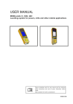
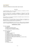
CNC TURNING CENTER
ⓥ 2. (05. 10)
World Top Class Quality
HYUNDAI-KIA Machine
High Speed, High Accuracy, High Rigidity
CNC Turning Center
High Productivity, Versatile & Integrated Lathe
■ High Speed, High Accuracy
■ High Rigidity, ensures Long Tool Life and
Machining Accuracy
■ Integrated Operation
■ Easy Control
■ Convenient Operation
MAX. SWING ON BED
MAIN SPINDLE SPEED
SUB SPINDLE SPEED
SPINDLE MOTOR
SKT15 Series
SKT21 Series
Ø550mm(21.7″)
6,000rpm
6,000rpm
11/7.5kW(15/10HP)
Ø550mm(21.7″)
4,000rpm
6,000rpm
15/11kW(20/15HP)
2 3
Speed & Power
To Realize The Best Productivity
″/ 8″
″CNC Lathe
Popular 6″
CNC Turning Center SKT15/21
Series
Reduce Non–Cutting Time with High Speed Rapid Traverse
0
36m/min(1,417ipm) : 0.1sec
Rigid and Reliable
Servo Turret Index
High-performed AC servo motor and highaccurate 3-pieces coupling construction.
Powerful turret clamping force by hydraulic
system. (3,390kgf, 7,458lbf)
Wide Range of Constant Power
The wide range of constant power enables the
machine to do an excellent heavy duty cutting at low
speed with high power and torque of spindle motor.
No. of Tool
12 Stations of Tool : ID and OD tool holder can be
attached at any position.
- SKT15 7.14kgf-m (51.1ft-lbf)
- SKT21 29.22kgf-m (211.3ft-lbf)
Tool Size
SKT 15
25×Ø32mm ( 1″×Ø1.25″)
SKT 21
25×Ø40mm ( 1″×Ø1.57″)
Indexing Time
SLT15 Series
SLT21 Series
1step 0.2sec full (6step) 0.6sec
Rapid Traverse (X/Z)
36m/min (1,417ipm)
Output
Torque
Output
Torque
One Bed Cast ConstractionContains High–Accuracy & High–Rigidity
At the saddle, Built-in Construction has been applicated to X-axis to get much rigidity & accuracy
that make users be satisfied.
4 5
Accuracy
CNC Turning Center SKT15/21 Series
Thermally Symmetrical Headstock
Spindle is supported with angular contact ball
bearings in the rear for high-accuracy and rigidity.
Quick spindle Acc./Dec. Time
Accelerating and decelerating time of the main spindle is
greatly reduced in comparison with other machines by highperformance of spindle motor.
Gearless Type Spindle
Spindle has a wide range of generating power and is
designed for minimizing thermal distortion as a highprecise lathe. It can be obtained a high-accuracy during
high- speed operating, as well as reducing a noise and
realizing a good surface roughness due to gearless type
spindle.
High Rigid and Excellent damping ability
of Roller Guide
Excellent damping
Pre-tensioned and Double Anchored Ballscrew
ROLLER
BALL
11ms
BALL
2.7㎛
Each Axis is designed with a large diameter ballscrew,
fixed by double anchor on both ends, to provide
you with high-rigidity and minimize
thermal distortion.
ROLLER
1.6 ㎛
High rigidity
32ms
Direct Connection Servo Motors
with Ballscrews
By directly connecting ballscrews of every axis with
servo motors, it makes possible to obtain high
accuracy.
One - piece built-in casting construction greatly
improves rigidity and accuracy with high power
and torque .
High-tolerance & Excellent Cutting Capacity
Cutting Condition
ROUGH CUTTING
MATERIAL
SPINDLE SPEED
2,300 rpm
DEPTH OF CUT
1.5 mm (0.06″)
FEED
0.3 mm(0.01″)/rev.
COOLANT
USE
DIA. OF WORK
Ø42 (1.6″)[2 PASSCUT]
TOOL
※ This data is taken after full warming up operation.
FINISH CUTTING
BRASS
2,700 rpm
0.02 mm(0.0008″)
0.02mm (0.0008″)/rev.
USE
Ø36 (1.4″)[1 PASSCUT]
DIAMOND
6 7
Versatile functions
Q-Setter
CNC Turning Center SKT15/21 Series
Easy Work Coordinate Setting
Work coordinate is automatically set by just
input the cut off depth on control panel as a
parameter after slightly cutting the work
surface. Neither measuring nor calculating is
needed, and work coordinate can be set
within 30 seconds.
SKT15/21 Series
Provides you with superior rigidity and accuracy
Live Tool [LM & LMS Series]
VDI live tool enables the machine to do continuous
Drilling and End-milling after turning with one setup. This integrated operation greatly reduces setup time.
The tool offset is to be automatically memorized by
tools, touching onto the Q-setter without so much
time of trial cutting, measuring, tool offset input and
so on. Even a beginner can finish tool compensation
within 40 seconds with it.
No. of Tool on Turret : 12EA
- Live tool could be installed at every station regardless
of X and Z direction
One–touch Tailstock
Complete tailstock positioning within 9 sec. by only
pushing button.
Minimize non-cutting time by doubling the retract
time.
Forward : 3 m / min (118 ipm)
Retract : 6 m / mi n (23 6 ipm)
Forward
Forward
Jog
Retract
Jog
Move while button is pressed
Thrust = 450kgf
(990 lbf)
Max. Speed of Live Tool
4,000 rpm
Motor Output of Live Tool
AC 3.7 kW (5HP)
15/21:400(15.7″)
15L/21L:500(19.7″)
Clamping and unclamping are fully automatic. No
tightening or loosening of bolts are required.
When machining of a work with long length, center
drilling, center forward and turning operation can be
integrated as one operation. Therefore, non-cutting
time and set-up time are greatly reduced.
Parts Catcher (Option)
Main
Live Tool Capacity
- Drilling
: Ø20mm (3/4″)
- Tapping
: M16 (5/8″)
- End - milling
: Ø20mm (3/4″)
Tail Stock
Sub
This device automatically collects the finished
works, after job completion, without opening the
door.
Parts catcher is available not only for main
spindle but also for sub spindle. Parts are
completely finished through the combination of
Bar feeder, live tool, sub spindle and final sub
spindle parts catcher. At the same time both side
of machining was completed without operator's
loading & unloading.
Sub spindle & B-Axis
Chuck Size : Ø135mm(Ø5.3″)
Sub-spindle speed : SKT15/21LS,LMS (6,000 rpm)
Motor : AC 3.7/ 2.2 kW (5/3HP)
Rapid Traverse of B axis : 30m / min(1,181 ipm)
°Degree Indexing device is available
5°
for complicated applications (Option)
Synchronizing of Sub-Spindle
With Main Spindle
As the turning operation of outer diameter with
main spindle is completed, then the subspindle synchronize with main spindle to pick
up the work for machining the back surface
while the main spindle is rotated.
8 9
Convenience
CNC Turning Center SKT15/21 Series
Tooling System
SKT15/21 Series can
provide a variety of choices for factory automation
C–Axis for Live Tool
SKT15/15L/21/21L
QJC Chuck (Option)
SKT15:
SKT21:
The QJC chuck is not the
conventional type chuck which
is assembled by blots and
serration. It only takes a minute
to change precise three jaws of
OJC chuck to another
SKT15:
SKT21:
This function is available for limited
models (LM,LMS Series)
Big-Bore for Bar Feeder
SKT15 : MAX Ø45mm (1.77″)
■S
SKT21 : MAX Ø66.5mm (2.62″)
■S
ITEM
UNIT
Bar Capacity
SKT15
SKT21
mm (in) Ø45 (1.77″) Ø66.5 (2.62″)
Spindle Hole Size mm (in)
Ø51 (2″)
Hollow Chuck Size mm (in) Ø165 (6″)
Better Chip Disposal
Chips fall directly into the chip box. The
separate type chip box can be easily
cleaned. A large opening in the right side of
the machine is provided for easy chip
discharge.
SKT15LS/21LS
Ø78 (3.07″)
Ø210 (8″)
Separated Coolant Tank
Separated coolant tank has large capacity
[145l(38gal)]and is designed to prevent the machine
body from heat transfering and to ensure easy
cleaning and cooling.
For chip disposal
and coolant return
For coolant pumping
〈Option〉
Tools are not provided
10 11
Specification
CNC Turning Center SKT15/21 Series
Tooling System
Tooling Interference
SKT15LM/21LM
Unit:mm(in)
SKT 15/15L
SKT 21/21L
2
Ø3
Ø4
0
50
Ø
SKT 15LS
5
Ø13
0
Ø25
9
57
Ø165
35
Ø
Ø
0
Ø21
65
Ø1
Ø135
0
Ø
Ø16
5
Ø
35
0
21
0
SKT 21LS
Ø
1
Ø
5
Ø16
SKT 15LM/21LM
.
34
SKT 15LMS/21LMS
6
45
45
Ø20
5
60
Ø
7
9.
13
Ø
Ø210
Ø210
Ø20
Ø2
Ø25
13
10
13
.8
5
Ø
5
16
Ø
20
Ø
0
16
Ø40
SKT15LMS/21LMS
35
60
5
Ø3
Ø
8
0.
21
50
Ø3
Ø
40
Ø6
25
.3
75
Ø1
9.7
Ø13
Ø
0
Ø15
Ø25
Ø6
60
Ø1
External Dimensions
Ø139.7
Ø3
2
Ø2
0
Ø3
2
40
Unit:mm(in)
Chip wagon (Option)
SKT21LMS
WORLD INDUSTRIES ACE
E
D
B
Rear chip conveyor (Option)
Right chip conveyor (Option)
Chip wagon (Option)
C
C
A
A
F
SKT15
SKT21
SKT15L/21L
SKT15/21LMS
A
2,400 (94.7)
2,400 (94.7)
2,900 (114.2)
3,150 (124)
B
1,870 (73.6)
1,870 (73.6)
1,870 (73.6)
1,870 (73.6)
C
1,650 (64.9)
1,650 (64.9)
1,650 (64.9)
1,650 (64.9)
D
864 (34)
864 (34)
864 (34)
864 (34)
F
E
500 (19.7) 1,143 (45)
500 (19.7) 1,143 (45)
500 (19.7) 1,050 (41.3)
500 (19.7) 1,050 (41.3)
Tools are not provided
12 13
Specification
CNC Turning Center SKT15/21 Series
Tooling Travel Range
Unit:mm(in)
Tooling Travel Range
Unit:mm(in)
SKT15/21 [SKT15L/21L]
I.D Tool Holder
O.D Tool Holder
SKT 15LMS/21LMS
O.D, Double O.D Holder
I.D Tool Holder
Double I.D Holder
Live Tool (Axial)
SKT 15LS/21LS
O.D Tool Holder
Double I.D Tool Holder
SKT 15LM/21LM
O.D Tool Holder
I.D Tool Holder
Live Tool (Radlal)
SKT 15LM/21LM
Live Tool (Axial)
Live Tool (Radlal)
14 15
Specification
CNC Turning Center SKT15/21 Series
Controller
Specifications
ITEMS
15
15L
21
21L
SWING OVER BED
MAX. TURNING DIA.
MAIN
CHUCK SIZE
SUB
CAPACITY
SWING OVER CROSS SLIDE
MAX. TURNING LENGTH
BAR CAPACITY
MAIN
SPEED
SUB
mm(in)
Ø 350(13.8″
mm(in)
Ø
Ø 210(8″)
165(6″
)
mm(in)
mm(in)
mm(in)
mm(in) 410(16.14″) 530(20.87″) 410(16.14″)
Ø 45(1.77″)
Ø 66.5(2.62″)
mm(in)
6,000
4,000
rpm
rpm
Ø 80(3.1″)
Ø110(4.33″)
mm(in)
MAIN
SPINDLE Bearing inner Dia.
mm(in)
SUB
A2-5
A2-6
MAIN
ASA
NOSE
SUB
ASA
st
NO. OF TOOLS
25 / Ø 32
mm(in)
TOOLS DIMENSION
(1) (1¼)
0.2/0.4
INDEXING TIME(1 STEP/FULL) sec
TURRET
MECHANISM
—
MILL TOOL SPEED
rpm
DRILL/TAP SIZE
RAPID
TRAVERSE
FEED
TRAVEL
TAIL
STOCK
X
Z
B
21LMS
Ø550(21.7″)
Ø 255(10″)
Ø 350(13.8″)
Ø 255(10″)
Ø 165(6″)
Ø 210(8″)
Ø 165(6″)
Ø 210(8″)
Ø 165(6″)
—
Ø 135(5.3″)
Ø 350(13.8″)
Ø 210(8″)
m/min(ipm)
m/min(ipm)
m/min(ipm)
—
min-1
210(8.3″)
mm(in)
mm(in) 430(16.93″) 550(21.65″) 430(16.93″)
mm(in)
21LM
Ø 45(1.77″)
6,000
15LS
21LS
530(20.87″)
Ø 66.5(2.62″) Ø 45(1.77″) Ø 66.5(2.62″)
4,000
6,000
4,000
—
Ø 80(3.1″)
Ø110(4.33″)
Ø 80(3.1″)
A2-5
A2-6
A2-5
Ø110(4.33″)
—
MAIN
kW(HP)
SUB
X
FEED
Z
B
ELECTRIC POWER SUPPLY
kW(HP)
kW(HP)
kW(HP)
kW(HP)
KVA
MOTOR
WEIGHT
11/7.5
(15/10)
FANUC 0i-T
Ø 45(1.77″) Ø 66.5(2.62″)
6,000
4,000
6,000
Ø 80(3.1″)
Ø110(4.33″)
ITEM
Controls
Ø 60(2.36″)
A2-6
—
A2-5
A2-6
12
25 / Ø 32
(1) (1¼)
0.3/0.6
25 / Ø 32
(1) (1¼)
0.2/0.4
Spindle Functions
—
4,000
Ø20/M16
(Ø3/4, 5/8 ″)
—
36(1,417)
36(1,417)
—
—
210(8.3″)
550(21.6)
—
11/7.5
(15/10)
100
220(8.7″)
750(29.5″)
—
—
—
—
15/11
(20/15)
11/7.5
(15/10)
—
15/11
(20/15)
11/7.5
(15/10)
15/11
(20/15)
3.7/2.2(5/3)
3 (4)
3 (4)
Feed Functions
—
20
4,000 4,300 4,100 4,400
kg(lbs)
(8,900) (9,500) (9,100) (9,680)
Programming Functions
30(1,181)
100
220(8.7″)
15/11
(20/15)
Least Command Increment
25 / Ø 32
(1) (1¼)
0.3/0.6
SERVO
4,000
Ø20/M16
(Ø3/4, 5/8 ″)
1.6 (2.13)
4,300
(9,500)
25
4,400
(9,680)
30
4,500
(9,900)
4,400
(9,680)
4,500
(9,900)
FANUC 0i-T [FANUC 21i-TB]
CONTROLLER
※ Specifications are subject to change for improvement without notice.
STANDARD
HYDRAULIC HOLLOW CHUCK
SOFT JAW
Q-SETTER
TOOL SOCKETS & SLEEVES
SPLASH GUARD
FLOOD COOLANT
WORK LIGHT
LEVELING PADS
OPTION
1SET
1SET(3EA)
1SET
1SET
1SET
1SET
1SET
1SET
Controlled Axes
Simultaneous Controllable Axes
Least Input Increment
FLATØ 115
MT4 / Ø 56(2.2″)
720(28.35″)
mm(in) 400(15.75″) 520(20.47″) 400(15.75″) 520(20.47″)
450(992)
kgf(lbf)
AUTO POSITION
TAPER / DIA
TRAVELS
THRUST
TRAVEL TYPE
SPINDLE
15LMS
—
mm(in)
X
Z
B
C
15LM
SPINDLE SPEED METER
1SET
SPINDLE LOAD METER
1SET
CALL LIGHT(YELLOW)
1SET
WORK COUNTER
(NC FUNCTION : DISPLAY ON THE CRT)
RUN HOUR DISPLAY
(NC FUNCTION : DISPLAY ON THE CRT)
CHIP CONVEYOR
(REAR / RIGHT)
CHIP WAGON WITH CASTER
AIR BLOW
(FOR CHUCK/THROUGH SPINDLE )
HIGH PRESSURE COOLANT
CHUCK OPEN - CLOSE
CONFIRMATION DEVICE
FOOT SWITCH FOR TAILSTOCK
SPINDLE INNER STOPPER
AUTO DOOR
BAR FEEDER INTERFACE
PARTS CATCHER
TOWER CALL LIGHT (3 COLORS)
Reference Functions
Spindle Speed Command
Spindle Speed Override
Spindle Orientation (1 Position)
Maximum Programmable Dimensions
Interpolation Functions
Cylindrical Interpolation
Absolute and Incremental Command
Constant Surface Speed Control
Decimal Point Input
Direct Drawing Dimension Programming
Miscellaneous Function
Canned Cycle : G90, G92, G94
Multiple Canned Cycle : G70 ~ G72, G74 ~ F76
Multiple Canned Cycle : G80 , G83, G83 ~ G88
Rigid Tap
Program Stop
Program End
Programmable Data Input (G10)
Manual Jog Feed : Rapid, Jog, Feed, Handle
Manual Handle Feed-rate
Feed Command
Feed-rate Override
Jog Override
Rapid Traverse Override
Override Cancel
Dwell
Manual Continuous Feed
Jog- Handle (Same Mode)
Incremental Feed
Manual Reference Point Return
Automatic Reference Point Return
Reference Point Return Check
Second Reference Point Return
SKT15/21,SKT15L/21L
SKT15MS/S, SKT21MS/S
2(X, Z) axes. (Max. 4 axes are available)
Max. 4(X, Z, B and C) axes
2 axes / Linear and circular. (Max. 4 axes) Max. 4(X, Z, B and C) axes / Linear and Circular
X axis : 0.001mm (0.0001″)
Z axis : 0.001mm (0.0001″)
C axis : 0.001deg.
X axis : 0.001mm (0.0001″)
Z axis : 0.001mm (0.0001″)
C axis : 0.001deg
S5 digits, Binary Output
50% ~ 150% (10Steps)
Provided
+/- 9999.9999″
Positioning/ Linear/ Circular (G00/G01/G02/G03)
Provided
G90 ~ 91
G96 SXXXX
Provided
Provided
M2
Turning, Threading, Facing
Finish, Rough, Peck Drilling, Grooving, Threading
Deep Hole Drilling, Tapping and Boring for X & Z
Provided
M00, M01
M02, M30
Provided
Provided
x1, x10, x100
F code Feed-rate Direct Command
0 ~ 200% (21 Steps)
0 ~ 2,000mm/min [79 ipm] (21 Steps)
F0, F5, F25/F50, F100%
Provided
G40, 0 ~9999.9999 sec
Simultaneous, 1 Axis
Provided
X1-1000
Provided
G28, g29
G27
G30
16 17
Specification
CNC Turning Center SKT15/21 Series
Controller
FANUC 0i-T
ITEM
Tool Functions
Coordinate Functions
Tape Functions
Other Functions
Tool Offset Amount
Tool Function
Geometry / Wear Compensation
Direct Input of Tool Offset Value Measured B
Tool Offset Amount
Tool Offest Pairs
Tool Life Management
Inch / Metric Conversion
Polar Coordinate Interpolation
Work-piece Coordinate System (G2 ~g 59)
Tape Code
Number of Register-able Program
Part Program Storage Length
Reader / Puncher Interface
Buffer Register (256Byte)
Custom Macro B
Manual Absolute :“ON”fixed
Block Skip
Optional Block Skip (/2 ~/9)
Backlash Compensation
Sequence Number Search
Program Number Search
Machine Lock
Program Check Function : Dry Run, Spindle Stop
Single Block
Function
Optional Chamfering / Corner R
CRT / MDI
Memory Lock
Language
Stored Stroke 1, 2, 3 (G22, G23)
Display of Spindle Speed and T code at all Screens
Self-Diagnosis Function
Emergency Stop
Stored Pitch Error compensation
Interlock
Back Ground Editing
Run Hour / Parts count Display
Actual Cutting Feed-rate Display
Erase CRT Screen Display
Program Restart
Graphic Display
Figures in inch are converted from metric values.
Design and specifications subject to change without notice.
SKT15/21,SKT15L/21L
SKT15MS/S, SKT21MS/S
G40 ~ G42
T7 + 1 / T6 + 2 digits
Provided
Provided
+/- 6 digits
32 Pairs
Provided
Provided
-
Provided
Provided
EIA RS-244-A/ISO 840 (Automatic Recognition)
200EA
320M (1,050 FT)
640M (2,100 FT)
RS232C
Provided
Provided
Provided
Provided
Provided
+/- 0 ~ 255 Pulses
Provided
Provided
All axis
Provided
Provided
G3, M3, T4, O4 digits
Provided
7.2″MONO LCD
8.4″Color LCD
Provided
English
Provided
Provided
Provided
Provided
Provided
Each Axis
Provided
Provided
Provided
Provided
Provided
Provided
Head Office
Gwangju Plant
Namsan Plant
Jungdong Plant
Banwol Plant
Gwangju Plant
Head Office & Factory
391-8 Kaumjung-Dong, Changwon, Gyeongnam, Korea
TEL : +82 55 280 9293, FAX : +82 55 285 8156
http : //www.wia.co.kr
E-mail : [email protected]
Seoul Office
837-36 LandMark Tower 15F, YeokSam-Dong, KangNam-Gu, Seoul, Korea
TEL : +82 2 2112 9780 FAX : +82 0 2112 9865
HYUNDAI - KIA MACHINE AMERICA CORP.
30 Murray Hill Parkway, Suite 300. East Rutherford, NJ 07073 U.S.A. TEL : +1 201 489 2887, FAX : +1 201 489 2723
http : //www.khiusa.com
E-mail : [email protected]
HYUNDAI - KIA MACHINE EUROPE GmbH
Karl-Hermann-Fiach-Str. 36, 61440 Oberursel, Germany TEL : +49 6171 9790 0, FAX : +49 6171 9790 30
E-mail : [email protected]
HYUNDAI - KIA MACHINE BEIJING
Room 908 No. 38 Xiaoyun Road, Chaoyang District, Beijing, China 100027 TEL : +86 10 8453 9850, FAX : +86 10 8453 9853
E-mail : [email protected]
HYUNDAI - KIA MACHINE SHANGHAI
Room 501 Ocular B/D, No. 1336 Wuzhong Road, Shanghai, China 201103 TEL : +86 21 5422 5370, FAX : +86 21 5422 5376
E-mail : [email protected]
HYUNDAI - KIA MACHINE GUANGZHOU
Room 1305 Citic Plaza No. 233 Tianhebei Road. Guangzhou, China 510613 TEL : +86 20 8752 1595/1596, FAX : +86 20 8752 1597
E-mail : [email protected]
Specification could be changed without notice
18 19