1
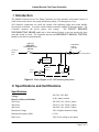
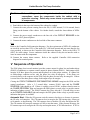
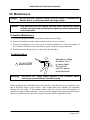
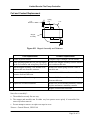
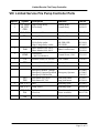
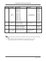
Hubbell Industrial Controls, Inc.
HUBBELL
A subsidiary of Hubbell Incorporated
50 Edwards St.
Madison, OH 44057
Telephone (440) 428-1161
FAX (440) 428-7635
Instruction Manual
Fire Pump Controller
Model LX-1500
Limited Service
Electric
Publication No. 197
April, 2000
Limited Service Fire Pump Controller
Table of Contents
I Introduction..................................................................................................................................3
II Specifications and Certifications ................................................................................................3
Specifications ................................................................................................................................3
Certifications .................................................................................................................................4
III Receiving, Handling, and Storage.............................................................................................4
IV Installation .................................................................................................................................4
V Sequence of Operation ................................................................................................................5
VI Start Up Procedure....................................................................................................................7
VII Maintenance .............................................................................................................................9
Preventive Maintenance.................................................................................................................9
Troubleshooting.............................................................................................................................9
Coil and Contact Replacement.....................................................................................................10
VIII Limited Service Fire Pump Controller Parts.......................................................................11
Attachments
Typical Controller Schematic
Typical Field Connection Diagram
Notes
Refer to job drawings for options.
For combination Automatic Transfer Switch/Fire Pump Controller applications, refer to
Publication No. 186 for the LX-250 Transfer Switch or Publication No. 195 for the LX-350
Transfer Switch, for details.
Page 2 of 12
Limited Service Fire Pump Controller
I Introduction
The Hubbell Limited Service Fire Pump Controller provides automatic and manual control of
small electric motor driven fire pumps and booster pumps of 30 horsepower or less.
All Controller components are inside the cabinet with indicating lights and switch handles
located next to the door. A pressure switch initiates automatic starting of the pump motor. The
Controller monitors the power phases and voltage.
The CIRCUIT BREAKER
DISCONNECTING MEANS handle has a door interlock feature to prevent opening the door
when the switch is closed. The Controller also has an EMERGENCY MANUAL CONTROL
handle to start the fire pump manually.
Incoming
Phase
Line
CIRCUIT
BREAKER
DISCONNECTING
MEANS
EMERGENCY
MANUAL
CONTROL
To
Fire Pump Motor
L1 M1 T1
Surge
Suppressor
Pressure
Switch
Control
Panel
PLM
Control
Transformer
Figure I-1 Block diagram of LX-1500 showing one phase
II Specifications and Certifications
Specifications
Voltage
208, 240, 380, 480C
Phase Loss/Reversal Module
A-B-C phase rotation
200 Series
300 Series
400 Series
208–240 VAC, 60 Hz, 3 phase
380–415 VAC, 50 Hz, 3 phase
440–480 VAC, 60 Hz, 3 phase
Maximum Voltage
10% of highest nominal voltage
Maximum Frequency Shift
0.1 Hz
Phase Loss
18% of low voltage in one phase
Page 3 of 12
Limited Service Fire Pump Controller
Undervoltage Trip
15% below set point
Time Delays
Pick-up, 1.5 s, fixed
Drop-out, 1.5 s, fixed
Output Relays
10 A, 120 VAC
5 A, 240 VAC
Indication
green LED, on for A-B-C phase rotation
Surge Suppressor
650 V rating
Temperature
Operating: −4° F to 104° F (−20° C to 40° C)
Storage: −4° F to 182° F (−20° C to 85° C)
Certifications
The Hubbell Limited Service Electric Fire Pump Controller is built to NFPA 20 requirements.
The Controller is listed by:
Underwriters Laboratory
Factory Mutual
Underwriters Laboratory Canada
New York City
Canadian Standards Association
III Receiving, Handling, and Storage
1. Immediately upon receipt, carefully unpack and inspect the Controller for damage that may
have occurred in shipment. If damage or rough handling is evident, file a damage claim with
the transportation carrier.
2. If the Controller must be stored, cover it and place in a clean, dry location. Avoid unheated
locations where condensation can result in damage to the insulation or corrosion of metal
parts.
IV Installation
1. Consult the motor nameplate to determine voltage, current, and horsepower rating and
compare with the Controller nameplate for matching data.
2. Release the door interlock by moving the CIRCUIT BREAKER DISCONNECTING
MEANS to the OFF position.
3. Inspect the control transformer’s primary connections for agreement with the line voltage of
the incoming power.
4. Exercise all switches and contactors, without power, to see that they operate freely.
5. Choose a location or base for the Controller that is non-combustible and within site of the
motor. The base should not be subject to excessive vibration that may cause erratic operation
of the PS (pressure switch). The Controller should be leveled so that the PS is level. Sight
across the PS cover screws.
Page 4 of 12
Limited Service Fire Pump Controller
Caution:
Before drilling and punching holes in the cabinet for wiring
connections, cover the components inside the cabinet with a
protective covering. Debris may cause shorts or prevent operation
of components.
6. Punch holes in the top or the bottom of the cabinet for conduit.
7. Connect the water pressure sensing line to the PS (1/4 NPT internal, 3/4-16 external, brass)
fitting on the bottom of the cabinet. For further details, consult the latest edition of NFPA
20.
8. Connect the power supply conductors to the line side of the CIRCUIT BREAKER in the
correct A-B-C phase sequence.
9. Connect the motor conductors to the load side of the motor contactor.
Note
Refer to the Controller field connection diagrams. Per the requirements of NFPA 20, conductors
are sized for no less than 125% of the motor FLC (full load current) and not more than the lug
sizes provided, as shown on the Controller field connection diagrams. Refer to the NFPA 70
(NEC) for cable ratings. Secure conductors inside the cabinet so they do not interfere with or
come in contact with the components.
10. Connect the remote alarm contacts.
diagram for terminal points.
Refer to the supplied Controller field connection
V Sequence of Operation
The PLM (phase loss/reversal monitor) provides contact output for phase loss and undervoltage
(PLM-2) in addition to a separate contact output for phase rotation (PLM-1). Both output relays
energize if all three phases are present and the phases are in the proper rotation. If a phase loss
or undervoltage condition occurs, only the phase loss relay de-energizes. If the phases are
reversed relative to the sequence on the PLM, only the phase reversal relay de-energizes. If there
is a total loss of the three-phase voltage, both output relays de-energize.
Closing the CIRCUIT BREAKER DISCONNECTING MEANS energizes the PLM and the
control transformer. After a 3–5 second delay, contacts PLM-1 open and the PHASE
REVERSAL light should go off. If there is a phase reversal, PLM-1 remains closed to turn on
the PHASE REVERSAL light and energize the PRR (phase reversal relay) to provide remote
indication of phase reversal. The PLM-2 contacts also close, after the 3–5 second delay, to turn
on the POWER AVAILABLE light and energize the PFR (phase failure relay) to provide remote
indication that power is available.
Automatic Start - When the PS (pressure switch) contacts close due to a decrease in pressure,
the CR relay coil energizes. The CR contacts close to energize the TR1 timing relay, factory set
at 10 minutes, to begin timing. The TR1 contacts close to latch the CR relay and bypass the PS.
The CR contacts also energize contactor coil M1 to start the motor. If the pressure increases, the
PS contacts open to de-energize the CR relay and stop the motor, if TR1 has timed out. If TR1 is
Page 5 of 12
Limited Service Fire Pump Controller
still timing, the CR relay remains energized and the motor continues to run for the duration of the
timer setting.
Pressing the STOP push button stops the motor even if TR1 is timing. If the Controller does not
have a TR1 timing relay, the pump motor runs until the STOP push button is pressed.
Manual Local Start - Pressing the START push button energizes relay LRSR. The LRSR
contacts close to latch the LRSR relay and energize the M1 contactor coil to start the motor. The
motor runs until the STOP button is pressed to de-energize the LRSR coil.
Manual Stop – Connecting the jumper wire between TB2-4 and TB2-5 bypasses the TR1
timing relay contacts. When this jumper is installed, the motor runs until the STOP button is
pressed.
Remote Start - The remote start circuit requires the closure of remote contacts to start the
motor. Closing the remote contacts energizes the LRSR relay. The LRSR contacts close and
latch the LRSR relay until the STOP button is pressed.
Deluge Valve Start – A normally closed remote switch energizes the optional deluge valve
relay (DVR). Opening the remote switch de-energizes the DVR, closing the DVR contacts in
parallel with the PS contacts, to energize the CR relay and the TR1 timing relay. When the
remote switch closes, the DVR contacts open to de-energize the CR relay and stop the motor, if
TR1 has timed out.
Lockout – (This feature is not allowed per NFPA 20 and is permitted only when acceptable to
the authority having jurisdiction.) The lockout circuit requires the closure of remote contacts to
stop the motor. Closure of the contacts energizes the LK relay. Contacts LK open to deenergize the CR relay and stop the motor. If the remote contacts open while the pressure is low,
the motor restarts.
EMERGENCY MANUAL CONTROL - The emergency start handle should only be used if the
Controller fails to start automatically or with the START push button. The motor runs until the
handle is returned to the OFF position or the CIRCUIT BREAKER is opened. To start the
motor when control power is not available, push the T-handle in and rotate counterclockwise
(45°°) to lock in the full ON position in a fast and continuous motion.
Caution: Failure to engage the handle in a fast and continuous motion can
result in damage to the contactor and failure to start the motor.
Pump Run Contacts - The pump run contacts transfer any time the M1 contactor is closed by
either electrical or mechanical means.
Phase Loss Contacts - The phase loss contacts transfer when line or control power is lost or
the line voltage drops more than 15 percent.
Phase Reversal Contacts - The phase reversal contacts transfer when there is a phase
reversal, rotation other than A-B-C.
Page 6 of 12
Limited Service Fire Pump Controller
VI Start Up Procedure
Danger: Shocks, burns, or death may result from high voltage.
Caution: Only personnel who are familiar with the power distribution system
and this manual should be allowed to perform this procedure.
1. Verify that the motor nameplate horsepower and voltage match the Controller nameplate.
2. Verify that the CIRCUIT BREAKER DISCONNECTING MEANS is open. Check with
the electrician to see if the Controller is connected directly to the main transformer. If so,
apply the Service Disconnect label above the CIRCUIT BREAKER handle operator.
3. Verify that the PLM is set to the line voltage.
4. Verify that the customer connections to the CIRCUIT BREAKER and contactor are properly
tightened.
5. Carefully remove the foam packing from the PS (pressure switch) between the mercury
switch and the bourdon tube. Remove the installation instructions above the tube. Replace
plastic cover.
6. Adjust the PS set points on the right side of the switch to meet water system requirements.
Set the upper pointer to the required STOP (HIGH) pressure setting. Set the lower pointer to
the required START (LOW) pressure setting.
The scale on the PS is only for initial positioning of the pointers. During testing of the
Controller, verify the PS settings by referring to the system pressure gage. Readjust settings
as necessary to obtain desired STOP and START settings. Refer to the instructions packed in
the PS and NFPA 20 for more information on adjusting the settings.
7. Verify that the minimum run timer TR1 is set for 10 minutes, per NFPA 20. The timer can
be field set as required by local jurisdiction.
8. Close the cabinet door and close the CIRCUIT BREAKER DISCONNECTING MEANS.
After a five second delay, verify that the POWER AVAILABLE light is on. If equipped with
a Transfer Switch, verify that the green LED on the PRM (phase reversal monitor) is on after
a five-second delay. If the LED’s are not on, open the CIRCUIT BREAKER and change
any two leads (L1, L2, and L3) on the PLM. If equipped with a Transfer Switch, change the
same two leads on the PRM.
Caution: Note that the pump should be primed and the water source available
before running to avoid damage to the pump. To avoid flooding,
ensure the sprinkler system is completely installed and ready to be
pressurized.
9. Bump the motor by pressing the START button and then press the STOP button, to check
for proper rotation. If not correct, open the CIRCUIT BREAKER and change any two leads
on the load side of the M1 contactor.
10. Press the START push button. Verify that the motor starts properly and runs at full speed.
Page 7 of 12
Limited Service Fire Pump Controller
11. Press the STOP push button to stop the motor.
12. Start and stop the motor with the EMERGENCY MANUAL CONTROL handle. Push and
rotate the T-handle in a quick motion to lock the contactor in the ON position to start.
Rotate the T-handle clockwise and release to stop the motor.
Caution: Failure to engage the handle in a fast and continuous motion can
result in damage to the contactor and failure to start the motor.
If equipped with an LX-250 or LX-350 Automatic Transfer Switch, complete the following
additional tests:
1. Verify connection of the engine generator set start wires to TB-1 and TB-2 at the top of the
LX-250 Transfer Switch power panel or to TB8-1 and TB8–2 on the left side of the LX-350
Transfer Switch power panel.
2. Close the FIRE PUMP (emergency) ISOLATING SWITCH and open the CIRCUIT
BREAKER. The Automatic Transfer Switch should transfer to the alternate source per
system requirements. Bump the motor to check for proper rotation. If incorrect, move the
FIRE PUMP ISOLATING SWITCH to the OFF position and switch the generator set off using
the switch located on the generator. Switch any two leads on the line side of the FIRE PUMP
ISOLATING SWITCH. Return the generator set control switch to the Auto position and close
the FIRE PUMP ISOLATING SWITCH. The generator set may start.
3. Operate the pump on the alternate (emergency) source using the START and STOP push
buttons.
4. Close the CIRCUIT BREAKER. The Control Module should now be sensing normal power
and timing for retransfer. Press the BYPASS RETRANSFER TO NORMAL push button to
return the Transfer Switch to the normal position.
Page 8 of 12
Limited Service Fire Pump Controller
VII Maintenance
Danger: Do not open the Controller cabinet until ALL power is disconnected.
Shocks, burns, or death may result from high voltage.
Caution: Only personnel who are familiar with the power distribution system
and this manual should be allowed to inspect or perform maintenance
on the Controller.
Preventive Maintenance
A. Protect the equipment against accumulation of dust and metal chips.
B. Protect the equipment against conditions that result in excessive moisture.
C. Exercise the equipment every week as part of routine maintenance to verify the integrity of
the Controller, Transfer Switch, generator set, power conductors, pump, and motor.
D. Field lubrication is not necessary or required for the Controller.
Troubleshooting
!
DANGER
Warning:
Hazardous voltage
will shock, burn,
or cause death.
Do not touch
until ALL power
is disconnected.
Disconnect ALL power supply sources to the Controller before
servicing to prevent shock or accident hazard.
Before attempting any troubleshooting on the Controller, verify that the cause of a problem is not
due to the motor, pump, or power source. Then visually inspect the Controller for component
damage and lose wiring. If the problem cannot readily be resolved, review the Sequence of
Operation section for proper operation. Then refer to the supplied wiring diagram and schematic
and use a volt/ohm meter to check the wiring to determine which component is faulty.
Page 9 of 12
Limited Service Fire Pump Controller
Coil and Contact Replacement
Coil
Retainers
Spring
Clip
Coil
Magnet
Assembly
Figure VI-1 Magnet Assembly and Retainers
Coil Replacement*
Contact Replacement*
1.
Isolate all power sources.
Complete steps 1 through 5 in left column.
2.
While pressing against the coil, pull up slightly
on the coil retainers and swing away from coils.
Remove the magnet assembly from the molded
cover and movable arm.
3.
Pull the magnet assembly, coil, molded cover,
and movable arm from the contactor.
Remove the return spring from the center of
movable arm.
4.
Remove the spring clip and remove the
armature from movable arm.
Remove the molded cover from movable arm.
5.
Remove the coil from the magnet.
Press and slide the movable contact and spring
from movable arm.
6.
Replace the coil and reassemble.
Remove the screws holding stationary contacts
in place and remove stationary contacts.
7.
Replace contacts and reassemble.
Notes for re-assembly*:
a. The molded cover only fits one way.
b. The magnet and movable arm fit either way but operates more quietly if reassembled the
same way before removal.
c. Do not attempt to remove or replace arc traps in cover.
*Source: General Electric, GEH-5168
Page 10 of 12
Limited Service Fire Pump Controller
VIII Limited Service Fire Pump Controller Parts
Spares
Symbol
Description
Function
Part No.
1
1
CR, LRSR
LK, PFR,
PRR
High Voltage Relay
2-Pole Relay
Starting Relay
Control Relay
31658141
31658123
2
FU1, FU2
Fuse, 1 A, MDL-1
Control Power
57361726
1
TR1
Timing Relay, octal
Min. Run Time
31658111
Octal socket
2-Pole Relay socket
High Voltage Relay socket
TR1
LK, PRR, PFR
CR, LRSR
48518012
48518018
48518022
Phase Monitor, 208–240 V
Phase Monitor, 440–480 V
Phase Loss/Reversal
57418398
57418399
Transformer,
208/230/380/460 V
Control Power, 120 V
57511355
PS
Pressure Switch, 10-300 PSI
1 NC contact
57501023
EPR
Pressure Recorder, 300 PSI
Battery driven
57501013
Operating handle
Circuit Breaker
57504087
Emergency Manual T-handle
Emergency Operator Push Rod
Emergency Push Rod Pin
Emergency Operator
91158006
91158005
57401033
Push button NO, green
Push button NC, red
Start push button
Stop push button
80320105
80320104
PL4, 5, 6, 7
Bulb
Indicating lights
80324905
PL4, 5, 6, 7
Lamp Socket
Indicating lights
402066520
Red lens
Clear lens
Phase Reversal
Power Available
402067520
402157520
Surge Suppressor
Surge suppression
402165820
1
1
1
PLM
XFMR
PB1
PB2
2
PL5, 6, 7
PL4
SS
Page 11 of 12
Limited Service Fire Pump Controller
Spares
Symbol
Description
CB
(Note 3)
Breaker, 15 A
Breaker, 20 A
Breaker, 25 A
Breaker, 30 A
Breaker, 40 A
Breaker, 50 A
Breaker, 60 A
Breaker, 70 A
Breaker, 90 A
Breaker, 110 A
Breaker, 125 A
Breaker, 150 A
M1
Contactor, 200/208
Contactor, 220/240
Contactor, 440/480
Function
Circuit Breaker
Discounting Means
Main Contactor
Contactor Coil, 200/208
Contactor Coil, 220/240
Contactor Coil, 440/480
M1a1, M1b1
Auxiliary Contact, M1
Part No.
57504463
57504373
57504371
57504103
57504378
57504389
57504346
57504347
57504348
57504541
57504101
57504344
57300333
57300330
57300331
57300570
57300571
57300573
Pump Run Contact
1 NO and 1 NC
Contact
57300391
Notes
1. Specify Controller serial number, model number, horsepower, and voltage when ordering
parts.
2. Refer to Bulletin 1000 for information on one-year parts and labor warranty.
3. Consult factory for Spectra Circuit Breakers with high interrupt ratings.
Page 12 of 12