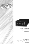
Download HTC MDA2 User's Manual
Transcript
Service Manual for MDA2 HTC Proprietary Confidential Treatment Requested Rev. 1.0 September 12, 2003 HTC Corp. Engineering Mobility HTC confidential © 2001, HTC Corporation. All rights reserved. TOTAL 43 CONT.ON. 2 PAGE NO. 1 TITLE: Service Manual for MDA2 REV. DATE NO. 1.0 Aug 26,2003 CONTENTS DEP. REVISED APP’D STGE.PER. TSD HTC confidential © 2001, HTC Corporation. All rights reserved. TOTAL 43 CONT.ON. 3 PAGE NO. 2 Table of contents 1. INTRODUCTION ・・・・・・・・・・・・・・・・・・・・・・・・・・・・・・・・・・・・・・・・・・・・・・・・・・・・・・ 4 2. PRODUCT SPECIFICATIONS ・・・・・・・・・・・・・・・・・・・・・・・・・・・・・・・・・・・・・・・・・・ 4 2.1 PRODUCT CONFIGURATION ・・・・・・・・・・・・・・・・・・・・・・・・・・・・・・・・・・・・・・・・・・ 4 2.2 SPECIFICATIONS OF MDA2・・・・・・・・・・・・・・・・・・・・・・・・・・・・・・・・・・・・・・・・・・・ 5 2.3 SPECIFICATIONS OF AC ADAPTER …………………………………………………5 2.4 GSM/GPRS FUNCTIONAL BLOCK PART ・・・・・・・・・・・・・・・・・・・・・・・・・・・・・ 5 3. SYSTEM BLOCK DIAGRAM ・・・・・・・・・・・・・・・・・・・・・・・・・・・・・・・・・・・・・・・・・ 10 4. SERVICING TOOLS ・・・・・・・・・・・・・・・・・・・・・・・・・・・・・・・・・・・・・・・・・・・・・・・・・・・・ 11 5. ASSEMBLING AND DISASSEMBLING ・・・・・・・・・・・・・・・・・・・・・・・・・・・・・・・・・・ 12 5.1 DISASSEMBLING ・・・・・・・・・・・・・・・・・・・・・・・・・・・・・・・・・・・・・・・・・・・・・・・・・・ 12 5.2 ASSEMBLING ・・・・・・・・・・・・・・・・・・・・・・・・・・・・・・・・・・・・・・・・・・・・・・・・・・・・・ 19 6. PROBLEM DIAGNOSTICS ・・・・・・・・・・・・・・・・・・・・・・・・・・・・・・・・・・・・・・・・・・・・ 26 6.1 LIST OF TEST JIGS ・・・・・・・・・・・・・・・・・・・・・・・・・・・・・・・・・・・・・・・・・・・・・・・・ 26 6.2 CLASSIFICATION OF NON CONFORMITY ・・・・・・・・・・・・・・・・・・・・・・・・・・・・・・・・ 27 6.3 TROUBLESHOOTING AND REPAIR ・・・・・・・・・・・・・・・・・・・・・・・・・・・・・・・・・・・・・ 28 7. DIAGNOSTIC PROGRAMS ・・・・・・・・・・・・・・・・・・・・・・・・・・・・・・・・・・・・・・・・・・・ 34 7.1 LIST OF TEST ITEMS ・・・・・・・・・・・・・・・・・・・・・・・・・・・・・・・・・・・・・・・・・・・・・・ 34 7.2 TEST ITEMS OPERATION ・・・・・・・・・・・・・・・・・・・・・・・・・・・・・・・・・・・・・・・・・・・・ 34 8. SPARE PARTS LIST & EXPLODED DIAGRAMS・・・・・・・・・・・・・・・・・・・・・・・・・・・・・・・・ 38 8.1 Exploded Diagrams 38 8.2 LIST OF SPEAR PARTS ・・・・・・・・・・・・・・・・・・・・・・・・・・・・・・・・・・・・・・・・・・・・・・・・ 39 APPENDIX ・・・・・・・・・・・・・・・・・・・・・・・・・・・・・・・・・・・・・・・・・・・・・・・・・・・・・・・・・・・ 40 A. CUSTOMER, RETAILER MISJUDGMENT・・・・・・・・・・・・・・・・・・・・・・・・・・・・・・・・・・ 40 B. REPAIR TROUBLE SHOOTING GUIDE ・・・・・ 41 HTC confidential © 2001, HTC Corporation. All rights reserved. TOTAL 43 CONT.ON. 4 PAGE NO. 3 1.Introduction This manual provides the technical information to support the service activities of the MDA2. This document contains highly confidential information, so any or all of this document should not be revealed to any third party. 2.Product Specifications 2.1 Product Configuration Standard Package Item Contain 1 Main Unit 2 USB Cradle 3 Stylus 4 AC Adapter 5 Earphone 6 Pouch, Leather Case 7 Service Kit 8 Quick Start Guide 9 User’s Manual 10 Battery Pack 2.2 Specifications of MDA2 HTC confidential © 2001, HTC Corporation. All rights reserved. TOTAL 43 CONT.ON. 5 PAGE NO. 4 Item Platform Specification • Microsoft Pocket PC 2003 phone edition - English, French, German, Italian, Spanish,Portuguese. • • Combined GSM/GPRS and PDA. 2 logical block (PDA and GSM/GPRS) solution, layout is integrated into one module • GSM/GPRS can be turned off to let PDA to run alone Outside Dimensions 69.9mm(W) x 130mm(H) x 19mm (T) Weight Less than 200g Battery Removable rechargeable Lithium Polymer battery 1200 mAh(Typical) Data retention time : 72 hrs Separated Back up battery(25 mAh,rechargeable), data retention time above 0.5 hrs Battery Life : 15 hrs of PDA Talk time : 2.5 ~ 4 hrs Standby : 180 hrs 2.3 Specification of AC ADAPTER AC Adapter AC input 100 ~ 240 Vac, 50/60 HZ AC input current : 0.2 A max Output voltage : 5V dc Output current : 2A (typical) 2.4 GSM/GPRS Functional Block HTC confidential © 2001, HTC Corporation. All rights reserved. TOTAL 43 CONT.ON. 6 PAGE NO. 5 GPRS/GSM module (Tri-band) GSM900: 880-915, 925-960MHz DCS1800 1710 ~ 1785,1805 ~ 1880 MHZ PCS1900 1850 ~ 1910, 1930 ~ 1990MHZ Antenna Generic GSM Service Internal Antenna Call forwarding Explicit Call Transfer Spool Icon Wave ring tone download /compose Long message (640 characters) SIM LOCK Network lock GPRS functionality GPRS Class B, Multi-slot Class 10 Memory ROM 32MB(Standard,CPU embedded) and 64/96/160MB (CPU embedded 32MB NOR Flash,32 bit Data bus + M-System 32/64/128 MB NAND Flash,16 bit data bus) 64MB(Standard model)SDRAM, and 128MB(enhanced model) RAM SIM 3V SIM Operation PDA Functional Block Processor TI Calypso + IOTA, GSM/GPRS solution Intel PXA263 CPU (Low power, High Performance,32 bit Clock Speed 400MHz LCD Module Transflective TFT-LCD with back light LEDs, 240 x 320 x 64K Sensitive Touch Screen Graphic Controller MPEG4 decoder 2D Graphic accelerator HTC confidential © 2001, HTC Corporation. All rights reserved. TOTAL 43 CONT.ON. 7 PAGE NO. 6 Interface One Infrared port IrDA SIR One 22 pin individual Port for signals (for USB, Serial, Car Kit, Power and Audio) One SIM card slot One SDIO/MMC card slot (B-Square SDIO driver) One 34 pin Back pack connector One Audio Jack (2.5 ψ) Stylus Lock Keyboard/Button/Switch One five way navigation button One Power button(wake-up key) One volume control button(up & down) Two phone button, SEND(Yes) & END(No) (Wake-up keys),with LED backlight type mechanism Two programmable AP buttons(Wake up key) Camera (Side button) Press to launch camera capture utility, and take picture for 2nd press Voice command/Voice recorder (side button) Press for voice command Press and hold for Voice recorder Reset Switch Key lock function support by software Notification One Bi-color LED for GSM standby, GSM message, GSM network status, PDA notification, PDA Charging status. One Blue LED for Bluetooth system notification of powered –ON and ready to transmit RF signal. Notification by sound, Message, Vibration on the display. HTC confidential © 2001, HTC Corporation. All rights reserved. TOTAL 43 CONT.ON. 8 PAGE NO. 7 Audio Microphone build in Software Echo cancellation Receiver Hardware AGC Hardware Full duplex WAV/WMA/MP3 stereo 16 bits with 8KHz,11 KHz,16KHz,22KHz,44.1 KHz, 48 KHz sampling rate CMOS Camera Color CMOS camera module VGA (480x640) resolution with JPEG encoder ALC (Auto Light Control) AWB (Auto White Balance) Preview Mirror on battery cover Camcorder QCIF, 15 fps(min), (in live mode)( max 15 seconds per clip) Operating in 5 Lux(Min) Cradle Cradle connector connected to main unit Audio jack (2.5 ψ) Microphone 2 slots, one for main unit + battery, another is capable of charging 2nd battery Serial or USB cable between cradle and PC LED indicator for 2nd battery charging Bluetooth Bluetooth 1.1 compliant Power class 2 Support Profile Generic access Generic object Exchange HTC confidential © 2001, HTC Corporation. All rights reserved. TOTAL 43 CONT.ON. 9 PAGE NO. 8 Accessories Retractable sync. Cable (USB/Serial) Cradle (USB, Serial) AC adapter Car adapter Stylus AC adapter with power plug Detacheable LCD protector Car Kit Stereo wired headset with mono microphone, volume control, Pick up/Hang up the incoming/Outgoing call, Call waiting, conference call, microphone mute. Mono Wired headset Stereo Bluetooth headset Option Battery (1200 mAh) Keyboard TTY Adaptor (Stereo > Mono in audio jack) Remote controller for VGA output Back pack : CF + TV/VGA out (within cable) + 600 mAh battery CF Slot support Wireless LAN GPS CF card Micro drive CDMA CF Card I/O card (Barcode reader,etc) Regulatory PTCRB (For North America Market) R&TTE FCC USB V1.1 Compliance test HTC confidential © 2001, HTC Corporation. All rights reserved. TOTAL 43 CONT.ON. 10 PAGE NO. 9 3.SYSTEM BLOCK DIAGRAM HTC confidential © 2001, HTC Corporation. All rights reserved. TOTAL 43 CONT.ON. 11 PAGE NO. 10 3. Servicing Tools This chapter provides information for the servicing tools for MDA2. List of Servicing Tools No. Item Use Remark 1 USB or Serial Cradle Check for Cradle I/F (Serial communication only) 2 USB DATA interface Cable Check for Cradle I/F (USB communication only) 3 Special Made Plastic Stick Disassembling for 4 SD Memory Card For SD card test 5 Earphone Headset For Audio test. 6 AC Adapter Power supply to MDA2. HTC confidential © 2001, HTC Corporation. All rights reserved. TOTAL 43 CONT.ON. 12 PAGE NO. 11 5. Assembling and Disassembling 5.1 Disassembling Tools needed for Assembling and Disassembling the MDA2 1. Lens Cleaning Tissue. 2. Flat Screw Driver 2.4mm 3. Philip Screw Driver #0. 4. Torex Screw Driver T6X40 5. Special Made Plastic Stick. 6. Tweezers. Remove the Stylus, SD Card slot Filler, and the Car antenna connector cover. 2 1 Next, Remove the Back cover by releasing the fixing lock as step 1. Then slightly push backward the back cover as step 2. Once Back cover is removed, you will find the battery on it. HTC confidential © 2001, HTC Corporation. All rights reserved. TOTAL 43 CONT.ON. 13 PAGE NO. 12 Press Unlock and release the battery Remove the battery from unit Warning: To reduce risk of fire or burns, do not disassemble, crush, puncture, short external contacts, or dispose of in fire or water. Replace only with specified batteries. Recycle or dispose of used batteries properly. To separate the housing , Use the plastic stick to open the housing . Insert and gently twist into the gap between stylus hole and antenna cover. To separate the antenna cover, use the hook of plastic stick to release three hooks of antenna cover. HTC confidential © 2001, HTC Corporation. All rights reserved. TOTAL 43 CONT.ON. 14 PAGE NO. 13 There are three hooks which fix the antenna cover and bezel. Insert to the gap and slightly pull upward from right to left to release the hooks. Antenna cover is removed. Remove two screws which fix the antenna to MB. Screw P/N:72H00339-00 1 2 Remove 6 screws which fixed the housing and bezel. There are two types of screw 1 5 2 3 Screw 1~4 P/N 72H00338-00 4 6 Screw 5,6 P/N 72H00339-00 Now separating the housing. Use plastic stick to slide along the gap (Right side of unit, near stylus hole) HTC confidential © 2001, HTC Corporation. All rights reserved. TOTAL 43 CONT.ON. 15 PAGE NO. 14 Gently open the housing Turn over the housing to the other side as shown on picture. Once the housing is removed, next to remove 3 screws which fix the MB into bezel. P/N 72H00401-00 Gently and carefully release the LCM FPC by litting the connector lock upward using your finger or soft plastic tweezers. HTC confidential © 2001, HTC Corporation. All rights reserved. TOTAL 43 CONT.ON. 16 PAGE NO. 15 Then remove the Camera module by slightly releasing its FPC(1) and camera which is sticked with Double side tap on MB (2) 2 1 Turn MB to the other side and remove the Navigation button by pulling up. Correct position of Navigation button Use tweezers to remove the Vibrator HTC confidential © 2001, HTC Corporation. All rights reserved. TOTAL 43 CONT.ON. 17 PAGE NO. 16 The LCM, Speaker , MIC is located on upper part (Bezel side). To Disassembly LCM module Hold the entire assembly as seen on the picture , push aside the bezel and push the panel from front side simultaneously . Notice the starting location. Doing this to release the LCM from 4 hooks which located 2 at its right and left respectively. Then, gently pull out the LCM from its lower part hook . If the Speaker need to be replaced, remove two screw which fix the speaker . P/N: 72H00401-00 Speaker HTC confidential © 2001, HTC Corporation. All rights reserved. TOTAL 43 CONT.ON. 18 PAGE NO. 17 If MIC need to be replaced, just take it out from its place slightly by using tweezers. Take out the MB and disassembly procedure is done. The disassembly procedure is finished. HTC confidential © 2001, HTC Corporation. All rights reserved. TOTAL 43 CONT.ON. 19 PAGE NO. 18 5.2 Assembling Be noticed that if MB need to be replaced, need to apply insulation tape on lower right corner as shown on picture. Insulation tape P/N: 76H00469-00 P/N for this insulation tape : 76H00469-00 On the other side , need to apply 3 gasket on shielding cover. Remember to insert navigation button to its place. Gasket Next to paste 2 EA Poron (black) aside to SEND and END switch on MB. HTC confidential © 2001, HTC Corporation. All rights reserved. TOTAL 43 CONT.ON. 20 PAGE NO. 19 Next to apply one black poron aside to volume button Totally there are four places at MB need to be applied pre-assembly. Install the MIC into its place. Before Assemble LCM , be noticed to apply stylus poron on the rear side of LCM Be noticed that the poron should not exceed the edge and interfere to bezel hooks. Insert the LCM starting from lower bottom part and insert into the rib. Make sure Poron should not exceed the edge to prevent interfere to the bezel’s hook and cause gap & stylus stuck LCM after assembly. Poron HTC confidential © 2001, HTC Corporation. All rights reserved. TOTAL 43 CONT.ON. 21 PAGE NO. 20 Next Push aside the bezel and insert the LCM to click into 2 hooks located on right and left respectively. Assembly the speaker and fix two screws on it. Apply 3 screws on MB Then insert the LCM FPC into the connector , make sure the FPC is fully inserted , then lock it by pressing the cover down. HTC confidential © 2001, HTC Corporation. All rights reserved. TOTAL 43 CONT.ON. 22 PAGE NO. 21 Next Camera module assembly. 1. Make sure the Aluminium foil is clean and workable. 2. Put the Camera on it. Place the Camera into correct position and fix it. Important Notice: Before inserting the FPC into its connector, use your finger to flat the FPC first (as shown on picture) the lock it. (The FPC is fragile , to prevent break ) Make sure Camera is fixed correctly. HTC confidential © 2001, HTC Corporation. All rights reserved. TOTAL 43 CONT.ON. 23 PAGE NO. 22 Next Close the Rear Housing to upper part starting from left side (with Volume button) TIPS: Adjust the volume button to its center first before full closing the Housing . Antenna Assembly Put the antenna into its place, starting from upper part, then press and insert its two ribs correctly to the housing. Then fasten two screws of the antenna. Continuing with 4 screws at the middle part of housing. P/N: Next two screws at the lower bottom P/N: HTC confidential © 2001, HTC Corporation. All rights reserved. TOTAL 43 CONT.ON. 24 PAGE NO. 23 FIX Antenna Cover Put the antenna cover and fix it starting from unit left side (side with volume button) Warranty Seal (Security Label) Be sure to apply new Warranty seal once the unit has been repaired before sending back to customer. In case of MB replacement, since the IMEI has to follow new MB IMEI, repair site is required to re-print Regulatory label to change IMEI no, but Serial No. should remain unchanged. Put the Battery into its place and lock it. HTC confidential © 2001, HTC Corporation. All rights reserved. TOTAL 43 CONT.ON. 25 PAGE NO. 24 Put back the battery cover. Put back the stylus, SD filler and Car antenna connector cover back into the unit. Now The unit is ready for performing TEST. The Unit Assembly is done ready for further tests. HTC confidential © 2001, HTC Corporation. All rights reserved. TOTAL 43 CONT.ON. 26 PAGE NO. 25 6. Problem Diagnostics 6.1. List of Test Jigs Item Name Usage RS-232 Serial Cable/Cradle For data port test USB Cable/Cradle For data port test Special Plastic Tool For unit disassembly AC Adapter For battery recharge and power related tests Earphone with Microphone For audio test SD Card or MMC Card For write protect, read and write test SD card with diagnostic For Function test diagnostic Personal Computer (PC) Use for Communication/Synchronization test Remark <Hardware Requirement for PC> O.S.: Windows 98/ME/2000 CPU: Pentium 166MHz or above Memory: 64MB~128MB PC Link: ActiveSync 3.7 HTC confidential © 2001, HTC Corporation. All rights reserved. TOTAL 43 CONT.ON. 27 PAGE NO. 26 6.2. Classification of Non-Conformity Non Conformity Types 1.Power Customer, Retailer Misjudgment A.Main unit does not respond to Power Button B.Main unit does not respond to Battery Switch 2.Operational A.Touch Panel does not respond to screen tap B.Buttons do not respond 3.Display A.Unusual vertical/horizontal lines or partial display B.Back Light does not turn ON/OFF 4.SD Slot A.SD Card cannot be used 5.Communication A.PC Connection (USB/Serial) not possible B.Wireless Connection (GSM/WAP/Pocket IE) not possible C.IrDA Connection not possible 6.Memory A.Data retention related problem 7.Battery A.Battery Pack does not Start B.Battery Discharges Quickly even after fully charged C.Battery Pack Does not Recharge 8.Sound A.No sound from Speaker or Distorted sound 9.Recording A.No recorded sound or distorted sound 10.Others A.Housing Cosmetic damage HTC confidential © 2001, HTC Corporation. All rights reserved. TOTAL 43 CONT.ON. 28 PAGE NO. 27 6.3 Troubleshooting & Repair Before attempting to Diagnose the unit received for repair, perform a Full Reset (Cold Boot) in advance. 1-A.Main Unit Does Not Respond to Power Button 1-B.Main Unit Does Not Respond to Battery Switch (1) Make sure the Battery is installed properly to activate the battery pack. (2) Connect the AC Adapter, maybe the battery pack is exhaust. (3) Check the Battery lock is close properly. (4) Try with another battery pack. (5) Replace battery pack if necessary. (6) Check all connections including LCD FPC to Main Board. Try with another Main Board. (7) Replace Main Board if necessary. (8) Once the defective part has been identified, verify it again with the defective part whether the symptom could be duplicated. 2-A.Touch Panel Does Not Respond to Screen Tap (1) Dismantle the unit, check the perimeter of Display between Front Bezel and Touch Panel surface for unusual foreign objects. Clean it, reassemble the unit and check the panel’s function again. (2) Check the connection of LCM FPC whether is properly connected. (3) Try with another LCM. (4) Try with another Main Board. (5) Replace LCM if necessary (6) Replace Main Board if necessary. (7) Once the defective part has been identified, verify it again with the defective part whether the symptom could be duplicated. HTC confidential © 2001, HTC Corporation. All rights reserved. TOTAL 43 CONT.ON. 29 PAGE NO. 28 2-B.Buttons Do Not Respond (1) Dismantle the unit, check the status of switches on the Main Board and the plastic parts of button of the Button not responding. (2) Try with another Main Board or Front Bezel. (3) Replace Main Board or Front Bezel if necessary. (4) Once the defective part has been identified, verify it again with the defective part whether the symptom could be duplicated. 3-A.Unusual Vertical / Horizontal lines or partial display (1) Check the connection of LCM FPC whether is properly connected. (2) Try with another LCM. (3) Try with another Main Board. (4) Replace LCM if necessary (5) Replace Main Board if necessary. (6) Once the defective part has been identified, verify it again with the defective part whether the symptom could be duplicated. 3-B.Back Light Does Not Turn ON/OFF (1) Check the connection of FPC whether is properly connected. (2) Try with another LCM. (3) Try with another Main Board. (4) Replace LCM if necessary (5) Replace Main Board if necessary. (6) Once the defective part has been identified, verify it again with the defective part whether the symptom could be duplicated. 4-A.SD Card cannot be used (1) Check whether SD or MMC Card is fully inserted to the slot until you hear a click. (2) Try with another SD / MMC Card and Check whether it is Write Protected. HTC confidential © 2001, HTC Corporation. All rights reserved. TOTAL 43 CONT.ON. 30 PAGE NO. 29 (3) Try with another Main Board. (4) Replace Main Board if necessary. (5) Once the defective part has been identified, verify it again with the defective part whether the symptom could be duplicated. 5-A.PC Connection (USB / Serial) not possible (1) Check whether “Connection Settings” in the MS ActiveSync is properly set. (2) Check whether it connects with other cables or cradle, customer’s cable might be damaged. (3) Check the external appearance of the connector on the unit whether it is physically damaged. (4) Replace Main Board if necessary. (5) Once the defective part has been identified, verify it again with the defective part whether the symptom could be duplicated. 5-B.Wireless Connection (GSM / WAP / GPRS) not possible (1) Make sure the user has been contacting the Carrier for SIM Card validation and activation. (2) Make sure the Wireless Connection Settings has been properly set. (3) Make sure the SIM Card is properly inserted to the SIM compartment. Make a life call or test it with the RF Test Station (Antenna Test). (4) Dismantle the Main Unit and check whether the Antenna is properly installed. (5) Try with another Antenna. (6) Try with another Main Board if necessary. (7) Once the defective part has been identified, verify it again with the defective part whether the symptom could be duplicated. 5-C.IrDA Connection not possible (1) Make sure the IrDA port settings on the Notebook or PC are properly set. (2) Make sure the IrDA function is properly activated on the Pocket PC and on the other device. (3) Make sure there’s no obstruction between the two devices in connection and within the distance. (4) Check the IrDA window whether it is broken or cracked. Replace Front Bezel if necessary. (5) Replace Main Board if necessary. (6) Once the defective part has been identified, verify it again with the defective part whether the symptom could be duplicated. HTC confidential © 2001, HTC Corporation. All rights reserved. TOTAL 43 CONT.ON. 31 PAGE NO. 30 6-A.Data Retention related problem (1) Back up battery is rechargeable, to retention purpose when main battery power is used up or when changing the main battery, Make sure to charge the unit if not use for a while. (2) Data introduced by User might be lost when Battery has drained completely. (3) Ask user to charge the Main Unit when latest warning message pops up. (4) Ask users to back up their data to the PC or SD card when expect stop using the unit for long period of time, for example, more than one week. (5) Charge the Main Unit and check if data looses even the Battery pack is charged or at least The unit still can be powered on without AC Adapter. (6) Check whether AC Adapter is functioning properly. (7) Check whether the condition of Battery Charging status is correct. (8) Check the appearance of Battery Pack. (9) Replace Battery Pack if necessary (10)Replace Main Board if necessary. (11)Once the defective part has been identified, verify it again with the defective part whether the symptom could be duplicated. 7-A.Battery Pack does not start (1) Make sure the Battery lock is closed properly. Data introduced by User might be lost when Battery has drained completely. (2) Connect to the AC Adapter and see if it takes charge. Also check AC Adapter condition. (3) Ask users to back up their data to the PC or SD card when expect stop using the unit for long period of time, for example, more than one week. (4) Charge the Main Unit and check if data looses even the Battery pack is charged or at least The unit still can be powered on without AC Adapter. (5) Check whether AC Adapter is functioning properly. (6) Check whether the condition of Battery Charging status is correct. (7) Dismantle the unit and check the appearance of Battery Pack. (8) Try with another Battery Pack or Replace Battery Pack if necessary (9) Try with another Main Board or Replace Main Board if necessary. (10)Once the defective part has been identified, verify it again with the defective part whether the HTC confidential © 2001, HTC Corporation. All rights reserved. TOTAL 43 CONT.ON. 32 PAGE NO. 31 symptom could be duplicated. . 7-B.Battery discharges quickly even after fully charged (1) Make sure the Battery Pack takes fully charge with AC Adapter. (2) Check whether the condition of Battery Charging status is correct. (3) Dismantle the unit and check the appearance of Battery Pack. (4) Try with another Battery Pack or Replace Battery Pack if necessary (5) Try with another Main Board or Replace Main Board if necessary. (6) Once the defective part has been identified, verify it again with the defective part whether the symptom could be duplicated. 7-C.Battery Pack does not recharge (1) Make sure the Battery Pack takes fully charge with AC Adapter. (2) Check whether the condition of Battery Charging status is correct. Charge should be done in no more than 3 hours. (3) Dismantle the unit and check the appearance of Battery Pack. (4) Try with another Battery Pack or Replace Battery Pack if necessary (5) Try with another Main Board or Replace Main Board if necessary. (6) Once the defective part has been identified, verify it again with the defective part whether the symptom could be duplicated. 8-A.No Sound from Speaker or Distorted sound (1) Check “Sound & Notifications” Settings in the unit for Sound Enabling. (2) Make sure it’s not MUTED. (3) Dismantle and Check whether the Speaker is properly installed (Orientation) (4) Replace Speaker if necessary. (5) Replace Main Board if necessary. (6) Once the defective part has been identified, verify it again with the defective part whether the symptom could be duplicated. 9-A.No Recorded Sound or Distorted sound HTC confidential © 2001, HTC Corporation. All rights reserved. TOTAL 43 CONT.ON. 33 PAGE NO. 32 (1) Check “Sound & Notifications” Settings in the unit for Sound Enabling. (2) Make sure it’s not MUTED. (3) Dismantle and Check whether the Microphone is properly installed (check or missing rubber) (4) Replace Microphone if necessary. (5) Replace Main Board if necessary. (6) Once the defective part has been identified, verify it again with the defective part whether the symptom could be duplicated. 10-A.Housing Cosmetic damage (1) Unless it is for Refurbishment, all housing replacement due to cosmetic damage shall be subject to be charged. HTC confidential © 2001, HTC Corporation. All rights reserved. TOTAL 43 CONT.ON. 34 PAGE NO. 33 7. Diagnostic Program 7.1. List of Test Items No. 1 Item RAM Test Description RAM Check Size/Write/Read/Comparison test. 2 Display Test Test the LCD display quality. 3 Touch Test Touch screen alignment test. Suggest to test in WinCE 4 Playback Test Play sound with 8KHz simulation wave. 5 Record Test Record audio sound and playback it(INT/EXT) 6 Button Test Test every most of button. 7 Checksum Test To show checksum value after Code reflash 8 B Light Test Back light ON with in different brightness level. 9 LED Test Test the message LED. 10 Battery Test Check the status of battery and AC power. 11 Vibrater Test 12 SD Test Test the function of the vibrater. SD card Write/Read/Write Protect test. 13 Clean Talk Time Clean Talk time(Air time) & Format PIM storage Remark CAUTION: This item is applied for refurbishment case only. For same unit repair back to customer is not necessary. 14 USB Test Suggest to test in Windows CE 15 Sir Test Suggest to test in Windows CE 16 Serial Test Suggest to test in Windows CE 7.2 Test Items Operation Power on the unit. While press and hold the Power Button, Action button and Reset the unit with the Stylus, release RESET button first about 1 second the to enter the Test Mode. You will find the display as following: HTC confidential © 2001, HTC Corporation. All rights reserved. TOTAL 43 CONT.ON. 35 PAGE NO. 34 Serial V1.01 Then, wait about 10 seconds, the display will show : Himalaya DIAG v1.00i RAM TEST Waiting for GSM ready Display Test --------- How to select test item: Using navigation button -"Up" or "Down" to select the test items How to execute the test program: Press “Action” to start the test No. 1 Item RAM Test Description Possible cause if fail Display Size and read/write test. It will show OK if pass. Could be M/B issue Stop on fail. 2 Disp Test Unit prompts for different display page to detect the defect of Could be LCD issue LCD, lines or dots. First display is WHITE screen, Press left to DARK screen Press UP to Multiple Color Press RIGHT for back to MENU HTC confidential © 2001, HTC Corporation. All rights reserved. TOTAL 43 CONT.ON. 36 PAGE NO. 35 3 Touch Test Tap the cross mark (+) with stylus on the correct location. Could be LCM issue Fail if no reaction Calibrate the screen following the + mark. Press ACTION to exit. 4 5 Play Test Record Test Play the tone with 8KHz/L-channel, then Could be speaker or Hear the sound and notice if bad sound quality happens M/B issue Select this item to record test, then press Action to start Could be MIC or M/B recording. It will automatically playback it. Then connect with issue earphone or external speaker and press action to check the record function is OK or not thru ext speaker. 6 Button Test Press each button to know if it works. Follow the instruction Could be switch or MB issue shown on the screen to finish the test item Stop on fail. 7 Checksum Verifies the checksum of the code. 8 B Light Test Back Light turns ON and Off, Check the light change Could be M/B or LCM Starting from Level 3 issue Press Action button to enter Level 2 Press Action button again to enter Level 1 Press Action again to enter Level 0 Action again for back to MENU 9 LED Test The message LED will show starting with RED Could be LED or M/B Press Action LED will change to GREEN issue Press Action LED will change to AMBER Press Action Key LED will ON (YES & END) Press again Action will back to MENU 10 Battery Test Test main battery and AC power source. Insert AC power Could be main battery CUR will show “+ “means charging , remove AC power CUR or M/B will show “-“ means internal power. Note: The Battery capacity shown is only for reference 11 Vibrator Test Check the vibrater Press action, units should vibrate. Press Action again back to MENU HTC confidential © 2001, HTC Corporation. All rights reserved. TOTAL 43 CONT.ON. 37 PAGE NO. 36 12 SD Test Insert SD card (Enable Write Protect) and start test. Pull out Could be M/B issue the SD card if you see the message< “Pluck OK ><Locked > Please remove locked SD . Adjust lock switch to unlock site (Disable Write Protect), and insert it. The program will read & write to SD card for test. Once finished, display will show Please remove SD card. Press Action back to MENU 13 Clean Talk Time Select this item to clean AIR TIME (Talk time) and Customer Use this item only for REFURBISHMENT PIM data. CASE 14 USB Test Plug USB cable to connect PDA to PC then and check for Could be M/B issue the connection in WinCE. 15 16 SIR Test Serial Port Test Prepare another unit as ‘supporting’ site. On test unit, please Could be M/B issue choose ‘Test Target’ and press action button to start test. Suggest to test it in Before test, make the IR ports of them face to each other. Windows CE mode. Check this item in Windows CE mode. Could be M/B issue HTC confidential © 2001, HTC Corporation. All rights reserved. TOTAL 43 CONT.ON. 38 PAGE NO. 37 8.1 Exploded Diagrams & Spare part list HTC confidential © 2001, HTC Corporation. All rights reserved. TOTAL 43 CONT.ON. 39 PAGE NO. 38 Spare part list Item Description HTC P/N Using Q'ty 1 Speaker, MDA2 36H00177-00 1 2 GSM ANTENNA 36H00158-00 1 3 RECHARGEABLE BATTERY,LI-ION polymer,3.7V,1200m 35H00020-01 1 4 FRU, Main Board, GER, Phone, T-Mobile, 128 MB (Different 1 Country has different P/N) 99HY0020-00 5 CMOS Camera Module 54H00063-00 1 6 LCM, ACX502AKN,SONY 60H00011-00 1 7 BEZEL, PRE-ASSY T-MOBILE,HIMALAYAS 74H00170-01 1 8 HOUSING, PRE-ASSY, HIMALAYAS 74H00171-00 1 9 STYLUS, HIMALAYAS 74H00187-00 1 10 MICROPHONE ASSY,MD6022ARC-9,W/RUBBER BOOT,EMKA 36H00132-00 1 11 Vibrator,Cylinder type,A4A-05-WTB-3,C.I.Kasei, 36H00180-00 1 12 SCREW,PH,FLAT,M1.4X2.5,NYLOK,L1.5 72H00338-00 4 13 SCREW,TOREX, M1.6x8,NYLOK,L4.5 72H00339-00 4 14 SCREW,PH,FLAT,1.4X4,PT,BLACK 72H00401-00 5 15 JOYPAD,PRE-ASSY,HIMALAYAS 16 COVER,ANTENNA,PRE-ASSY,HIMALAYAS 74H00218-00 1 17 COVER,BATTERY,PRE-ASSY,HIMALAYAS 74H00219-00 1 18 RUBBER-COVER,ANTENNA-CONN,HIMALAYAS 76H00398-00 1 19 CONDUCTIVE-FABRIC,PCB,HIMALAYAS 72H00411-00 3 20 PORON,STYLUS,HIMALAYAS 76H00453-00 1 21 SECURITY LABEL,HIMALAYAS (WARRANTY SEAL) 77H00083-00 1 22 DUMMY, SD, CARD, HIMALAYAS 71H00651-00 1 23 INSULATOR,TAPE,PCB,HIMALAYAS 76H00469-00 1 24 PORON , PCB , 76H00473-00 2 25 ALUMINUM-FOIL,CAMERA,HIMALAYAS 72H00412-00 1 74H00202-00 ,stick on MB 1 Besides of shown on exploded diagram, there are some more parts as following: 1 Conductive fabric, use on camera 72H00410-00 1 2 Insulation-tape, use on camera 76H00471-00 1 Please Refer Spare Part List from our Logistic for complete one . HTC confidential © 2001, HTC Corporation. All rights reserved. TOTAL 43 CONT.ON. 40 PAGE NO. 39 Appendix A. Customer, Retailer Misjudgment Before attempt repairing the unit, make sure the type of reported failure could be clearly reproduced; otherwise, check with the customer or distributor once again to identify the problem correctly. The following are failure symptoms that are typical by misjudgment No. 1 Item Possibility No Power even the Built-in Battery switch is switched OFF or exhausted. power button is pressed While Back Light is turned OFF, the surrounding lighting will be reflected on the panel and in a dim location, it looks like the unit is turned OFF. According to the Power Management settings, the units will be switched OFF automatically. 2 Battery discharges quickly The battery life depends on the devices being used in SD Card Slot, and frequency of use of the Front light. These functions consume a lot of energy. Operating with front light ON, or using high energy consumption devices such as SD Memory Card will drain out the battery pack faster. HTC confidential © 2001, HTC Corporation. All rights reserved. TOTAL 43 CONT.ON. 41 PAGE NO. 40 3 Battery cannot be Using AC adapter that is NOT supplied with the unit. charged Charging the battery while operating the unit with heavy loadings could cause the temperature inside the unit to build up which could cause the unit stop charging. At this moment, the LED indicator will flash Yellow to notify user that the charging has been stopped. Or the temperature is extremely low will also stop charging. Since the extreme high or low temperature will cause the battery to discharge quickly, it has been designed to cut battery charge below 0℃ and above 35~40℃ to protect the battery pack. 4 Cannot make If the unit could pass the test with Loop back Interface card, the communications via possibility of unit malfunction becomes low. Then the following mobile phones through items could be the reason of problem such as location, timing, exclusive cable. signal strength, service provider’s mixed up, or problem with the mobile itself. Or could be incompatibility issue. 5 Cannot use SD/CF Cards which are not being pre-formatted. Memory Card SD card has been switched to Write Protect mode. Card not inserted completely, or bad contact between connector contacts. 6 Black or White dot on the screen. For LCD panel’s normal behavior, it is hard to find a panel without any bad pixel. Once the numbers of dots and the distance between them are within the specifications, it is allowed. 7 Touch Screen or Could be wrong operation. Program Buttons are Screen not properly aligned with the stylus calibration. not reacting. 8 Front Light dim, cannot Check the Front Light settings in Power Management settings turn ON, or shuts OFF automatically. 9 Cannot playback music, No sound or volume is When Battery low, the music playback becomes difficult and the volume could become lower. low. 10 Cannot execute Could be an incompatible software installed application programs 11 Operation is slow in Could be insufficient memory. Check amount of system memory. response HTC confidential © 2001, HTC Corporation. All rights reserved. TOTAL 43 CONT.ON. 42 PAGE NO. 41 12 Hang up Software being used sometimes is not fully compatible with the system. Execute many application programs simultaneously Software that requires big amount of memory spaces or the system memory is low or the files being used is fragmented. 13 System Memory is enough, but is shows Software that requires big amount of memory spaces or the system memory is low or the files being used is fragmented. insufficient. *Note: Nevertheless, the above symptoms could be solved by a warm boot or cold boot, make sure the warm/cold boot has been executed and try to reproduce the symptom reported. How to perform Warm Boot and Cold Boot : Warm Cold Boot : Boot : Reset the unit by pressing reset button. Press Power button and Reset the unit simultaneously. HTC confidential © 2001, HTC Corporation. All rights reserved. TOTAL 43 CONT.ON. 43 PAGE NO. 42 B. Repair Troubleshooting Guide HTC confidential © 2001, HTC Corporation. All rights reserved. TOTAL 43 CONT.ON. F PAGE NO. 43