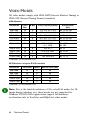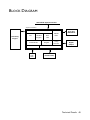
1
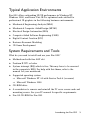
Fire GL2
User's Guide
Information in this document is subject to change without notice.
© 2000 Fire GL Graphics; All rights reserved.
TABLE OF CONTENTS
INTRODUCING THE FIRE GL2.........................................................1
ABOUT YOUR FIRE GL2 ................................................................................ 1
Hardware Design................................................................................. 1
Operating Systems .............................................................................. 2
Typical Application Environments................................................... 3
System Requirements and Tools ..................................................... 3
Performance Overview...................................................................... 4
HOW TO USE THIS USER'S GUIDE ................................................................ 5
Manual Conventions ........................................................................... 5
Viewing the User's Guide Online .................................................... 6
Do you Need a Printout
of the Online User's Guide? ............................................................. 6
QUICK INSTALLATION ................................................................................... 7
Installation Steps .................................................................................. 7
INSTALLING THE FIRE GL2 ..............................................................8
INSTALLING THE HARDWARE ....................................................................... 8
Preparing your Computer................................................................. 9
Installing the Card ............................................................................... 13
Connecting the Cables and
Completing the Installation ............................................................... 15
INSTALLING THE SOFTWARE ......................................................................... 18
Before you Start: Information, Tips, and Hints............................ 19
Software Installation for Windows NT4.0.................................... 20
Software Installation for Windows 2000 ...................................... 21
Contents
i
FIRE GL2 SOFTWARE UTILITIES ...................................................... 23
CHANGING THE VIDEO SETTINGS ................................................................24
How to Switch to the Display Properties?....................................24
Setting Resolution, Refresh Rate
and Color Depth..................................................................................25
Selecting your Monitor.......................................................................26
Adjusting the Monitor Display..........................................................29
MODIFYING APPLICATION PROFILES ............................................................32
REMOVING THE FIRE GL2 DRIVERS................................................ 35
TROUBLESHOOTING........................................................................ 36
COMMON PROBLEMS AND SOLUTIONS ......................................................36
TECHNICAL DETAILS ....................................................................... 39
FEATURES AND PERFORMANCE .....................................................................39
Hardware ...............................................................................................39
Software .................................................................................................42
PIN ASSIGNMENTS...........................................................................................42
VIDEO MODES .................................................................................................44
BLOCK DIAGRAM ............................................................................................45
TRADEMARKS AND REGULATORY .................................................. 46
TRADEMARKS...................................................................................................46
DISCLAIMER......................................................................................................47
EMI COMPLIANCE INFORMATION .................................................................48
ii Contents
INTRODUCING THE FIRE GL2
♦ ABOUT YOUR FIRE GL2
♦ HOW TO USE THIS USER'S GUIDE
♦ QUICK INSTALLATION
ABOUT YOUR FIRE GL2
Hardware Design
The Fire GL2 is an AGP/ATX card based upon the IBM RC 1000/
GT 1000 chipset.
The RC1000 256 bit graphics rasterizer provides the functionality of a
VGA controller, a 2D/3D raster engine with geometry pipeline setup
processor, and a 300 MHz RAMDAC. It also supports video streaming
by providing color space conversion and a bilinear scaling unit.
The GT1000 hardware geometry engine is a complete tranformation and
lighting engine with hardware implementation of the full open OpenGL
pipeline and most of the Direct3D geometry pipeline.
Introducing the Fire GL2
1
Operating Systems
The Fire GL2 supports the following operating systems:
♦ Microsoft Windows NT 4.0 with Service Pack 6 (or higher)
♦ Microsoft Windows 2000
♦ Linux - 2.2.x kernels, C Library 1.2 (LibC 6.2)
How to obtain Linux drivers?
⇒ Download from www.ati.com/support
Service Pack Information for Windows NT 4.0
You must be running Windows NT 4.0, updated with Service Pack 6 (or
newer) prior to installing the Fire GL2 drivers. The Service Pack is
available from Microsoft's web page, www.microsoft.com. For most
languages you can perform the Service Pack 6 update from the Fire GL
CD when you run the Quick Start utility.
2 Introducing the Fire GL2
Typical Application Environments
Fire GL2 offers outstanding 2D/3D performance in Windows NT,
Windows 2000, and Linux. Fire GL2 is optimized and certified for
professional 3D graphics in the following business environments.
♦ Mechanical Engineering Analysis (MEA)
♦ Mechanical Computer Aided Design (MCAD)
♦ Electrical Design Automation (EDA)
♦ Computer Aided Software Engineering (CASE)
♦ Digital Content Creation (DCC)
♦ Business Economic Modeling
♦ 3D Game Development
System Requirements and Tools
What do you need to install and use your Fire GL2?
♦ Motherboard with free AGP slot
♦ Pentium II CPU or better
♦ System interrupt (IRQ) which is free. This may have to be reserved
in the computer’s BIOS. For help with this theme, refer to the
manual for your mainboard.
♦ Supported operating system:
⇒ Microsoft Windows NT 4.0 with Service Pack 6 (or newer)
⇒ Microsoft Windows 2000
♦ CD-ROM drive
♦ A screwdriver to remove and reinstall the PC cover screws and card
mounting screws. See your PC manual for specific requirements.
♦ Fire GL CD-ROM for Fire GL2
Introducing the Fire GL2
3
Performance Overview
Note: For more detailed information on features and performance
please refer to the section Technical Details.
Hardware Performance
♦ 32-bit RGBα TrueColor 2D and 3D acceleration
♦ Accelerated, double-buffered 32-bit TrueColor up to 1920 x 1200,
at 75 Hz refresh rates
♦ 24-bit Z-buffer, 8-bit double-buffer, 8-bit single-buffer overlay
♦ Video engine supports YUV conversion, point and bilinear scaling
Software Features
♦ Multiprocessor system support
♦ ThreadSafe OpenGL 1.2 ICD support for dual processors.
♦ Supports Streaming SIMD Extensions (SSE) in Intel Processors
♦ Supports AMD Athlon™ processor-based systems with 3DNow!
technology
♦ Customized application settings for individual ISV applications
♦ DDC2B monitor support on all operating system platforms
4 Introducing the Fire GL2
HOW TO USE THIS USER'S GUIDE
For your convenience, this online User’s Guide has been formatted as
an Adobe® Acrobat® PDF file. This format gives you great flexibility
when using this documentation.
Many hyperlinks provide easy access to any information you may want.
To make it useful in a printed format, too, a - hyperlinked - table of
contents and page numbers are provided.
Because it was designed to be used online and printed, some of the
images may not print clearly or appear very clearly on screen.
Manual Conventions
Your Fire GL2 User’s Guide is organized in a standard, familiar way. A
few icons are used to point out important information:
This icon marks useful tips or important operational notes.
This icon is a warning about possible electrical/software hazards or
problems.
Introducing the Fire GL2
5
Viewing the User's Guide Online
You can also read the User's Guide online—important hypertext links,
such as Table of Contents entries, World Wide Web, and email
addresses are active.
Place your mouse cursor over Table of Contents entries or main
headings. If the hand icon changes to a pointing index finger, simply
click and you will move to that place in the document. Some email or
World Wide Web addresses inside this manual may be active as well.
Go directly to a Web, FTP site, or email program simply by clicking on
an active link. Displaying the provided bookmark and thumbnail views
may help you with the orientation and navigation in the User's Guide.
This manual might be displayed with slightly-reduced magnification in
your Reader. If you experience any difficulty reading certain files
online, use the Reader’s Zoom To feature from the View menu and
increase the magnification to about 133%. To view some screenshot
images perfectly clear you may need a larger magnification.
Do you Need a Printout of the Online User's
Guide?
You can easily print this User's Guide to access it off-line. The manual
then will look like any standard document with a table of contents and
page numbers.
For printing the User’s Guide, a print resolution of 600 dpi is
recommended.
6 Introducing the Fire GL2
QUICK INSTALLATION
♦ Brief instructions on how to get to work with the Fire GL2 in the
shortest possible time.
♦ Recommended for experienced users and system administrators
only.
♦ For more detailed information on installation and operation of your
graphics accelerator, please refer to the corresponding sections of
the Fire GL2 User’s Guide.
Installation Steps
1. De-install the drivers and software for your old graphics card.
2. Set the display driver to Standard VGA.
Disable any on-board graphics solution on the motherboard.
3. Shut down and disconnect your computer system.
4. Remove the installed (AGP, PCI, or ISA) VGA card.
5. Install the new Fire GL2 card.
6. Reassemble and connect your computer system.
7. Install the Fire GL2 drivers and configuration software from the
Fire GL CD:
⇒ automatic Quick Start utility or
⇒ Start > Run > START EXE
Introducing the Fire GL2
7
INSTALLING THE FIRE GL2
♦ INSTALLING THE HARDWARE
♦ INSTALLING THE SOFTWARE
INSTALLING THE HARDWARE
The hardware installation includes the following steps:
♦ Preparing your Computer
♦ Installing the Card
♦ Connecting the Cables and Completing the Installation
8 Installing the Fire GL2
Preparing your Computer
Information Before you Start
What do you need to
use your Fire GL2?
System Requirements and Tools
♦ Motherboard with free AGP 1.X slot for
the Fire GL2 card.
♦ System interrupt (IRQ) which is free.
This may have to be reserved in the
computer’s BIOS. For help with this
theme, refer to the manual for your
mainboard
♦ Pentium II CPU or better
♦ Supported operating system:
⇒ Windows NT 4.0 with Service Pack 6
(or newer)
⇒ Windows 2000
♦ A screwdriver to remove and reinstall
the PC cover screws and card mounting
screws. See your PC manual for specific
requirements.
♦ Fire GL CD-ROM for Fire GL2
What type of monitor
do you need?
Your Fire GL2 is optimally configured to be
combined with digital flat-panel (DFP) TFT
LCD displays and digital CRT displays. You
can also connect the Fire GL2 to highresolution MultiSync or multi-frequency
monitors or other VGA monitors.
Note: You can use the full power of the
graphics card only if your monitor supports
the horizontal (kHz) and vertical (Hz) refresh
rates as required by the graphics card. Refer
to your monitor's documentation for
recommended refresh rates.
Installing the Fire GL2
9
Where are the drivers?
♦
♦
Windows NT 4.0 and Windows 2000
drivers are provided on the Fire GL CD.
Linux drivers are available for
downloading from www.ati.com/support.
Are you installing your
Fire GL2 in place of a
card from another
manufacturer?
Before you shut down your computer and
remove the installed graphics solution , we
recommend that you un-install the old card
first:
♦ Use the uninstall program for your
existing card, if one is available. Consult
the documentation for your old card if
necessary.
♦ If no uninstall program is available, install
the standard VGA driver via the Display
Properties applet. For more
information refer to Setting the Display
Driver to Standard VGA.
Do you have an
integrated graphics
solution on the
motherboard?
Please refer to the manual or contact your
motherboard manufacturer to determine
how to disable your on-board graphics.
Plug-n-Play?
The card has been designed to take
advantage of 'plug–n-play' without requiring
additional hardware installation or
configuration.
The illustrations do not
show your card?
The illustrations provided in this section are
for instructional use only; the card shown
may look different than the one you
purchased.
10 Installing the Fire GL2
Setting the Display Driver to Standard VGA
To avoid possible driver conflicts between your old and new graphics
card, install the standard VGA driver for your operating system. Install
the standard VGA driver before you shut down your computer and
remove the installed (AGP, PCI, or ISA) VGA card.
Note: Installing the standard VGA driver is not required for
Windows 2000.
The applications for which you want to install drivers also have to be
completely installed for Standard VGA - 640 x 480 on your system
prior to using the new software. It is a good idea to do this before
removing an existing graphics adapter as not every application may
permit the configuration of its video mode from the operating system
level.
Installing the Standard VGA Driver for Windows NT 4.0
1. From the Start menu, go to Start > Settings > Control Panel,
then double-click on Display. The Display Properties sheet
appears.
2. Click the Settings tab; then click the Display Type button.
3. Under Adapter Type, click the Change button. The Change
Display window appears.
4. Under Manufacturers, select (Standard display types). Under
Display, choose VGA compatible display adapter.
5. Click OK. You may need to insert your Windows NT 4.0 CD-ROM.
6. Click Close and OK as often as necessary to accept the changes.
7. Windows asks you if you want to restart your computer. Click No.
8. Shut down your computer. You are now ready to remove your old
graphics card and install your new Fire GL2 card.
Installing the Fire GL2 11
Opening the Computer Cabinet
Warning! Prevent static electric damage. Avoid touching any
electronic components. Static discharge can cause severe damage to
electronic equipment, but here are some easy ways to see that it doesn't
happen:
⇒ Don't touch edge connectors or exposed circuitry.
⇒ If possible, ground your body. A metal power supply in your
computer is generally considered the best place to ground
yourself.
⇒ Make as few movements as possible to avoid building up static
electricity from your clothing, carpets and furniture.
1. Switch off your computer and all external options (printer, display,
and others) and unplug all power cables from the electrical source.
Physically remove the power cable from the system and wait 15-30
seconds for Flea Power to dissipate. Damage can occur to add-in
components if power is not physically disconnected from the
system during installation procedures.
2. Remove the cover of the computer. Refer to the instructions in your
computer’s manual for more information.
12 Installing the Fire GL2
Installing the Card
To install your Fire GL2 AGP card, follow these steps:
1. Locate the AGP slot.
2. Remove the metal slot cover. Save the screw to secure the graphics
card later.
3. Hold the card by the edges and position it directly above the AGP
slot. AGP cards are designed to fit one way only. Be sure your card
is properly aligned.
4. Insert your Fire GL2 card firmly into the AGP slot. Take care to
press it evenly and snugly into its slot. Do not force.
5. Align the slot in the mounting bracket of the card with the screw
hole in the rear panel of the computer case. Use the screw you
removed from the expansion slot cover or a previously installed
video adapter to secure the card in place.
Installing the Fire GL2 13
Installation in an AGP expansion slot
1 Fire GL2 card
2 Card edge connector
3 Expansion slot
You may prevent a possible overheating risk, if you - whenever possible
- leave the PCI expansion slot immediately next to the AGP slot free.
Reassembling your Computer
1. Secure ribbon cables and gently push them down and out of the
way before you replace the system cover.
2. Replace the computer cover.
3. Reconnect any peripheral equipment cables you may have
disconnected.
14
Installing the Fire GL2
Connecting the Cables and Completing the
Installation
Connecting the Monitor Cable
Note - You may connect only one monitor, either analog VGA or
digital CRT / TFT-LCD, to the Fire GL2. The Fire GL2 does not support
two monitors connected to one card. If you connect two monitors to the
card, the analog monitor is automatically active and the digital monitor
is automatically inactive.
VGA Monitor
Securely attach your monitor's data cable to the 15-pin VGA output
connector (1) on the card. Attach the cable to the monitor according to
the monitor's instructions.
Digital Flat-Panel TFT-LCD Monitor or Digital CRT Monitor
Securely attach your monitor's data cable to the 24-pin DVI output
connector (2) on the card. Attach the cable to the monitor according to
the monitor's instructions.
Installing the Fire GL2 15
Setting the Monitor Impedance
If you can switch the impedance values on your monitor, use the
following recommended settings:
R, G, B video input: 75 Ohm
Synch: 2.2 kOhm
Try other 'Synch' settings if you cannot achieve a stable video image.
If the impedance setting options are 'High' and 'Low' only, try the
setting that provides the most satisfactory monitor display.
Connecting the Stereo Glasses
You need this information only if you want to use StereoGraphics’
CrystalEyes or compatible stereoviewing eyewear.
Please note that stereo glasses are optional equipment and not included
in the Fire GL2 package.
Connect your stereoviewing eyewear to the 3 pin Mini-DIN stereo sync
connector (3) on the card.
Note: If the connector on your stereoviewing eyewear does not fit into
the Mini-DIN connector on the card, please contact your supplier or the
manufacturer of the stereo glasses for information on how to obtain an
adapter cable.
16
Installing the Fire GL2
Start your System
Switch on your monitor before you switch on your computer. Failing to
do so could damage your monitor.
If you have correctly installed the card, operating system messages will
appear on your monitor when the boot procedure is finished.
Note: Your monitor is running in standard VGA mode. Higher
refresh rates etc. are not available at this stage of the installation.
After you have successfully installed the Fire GL2 drivers you can
use the dialogs in the Display Properties menu to adjust the video
settings.
Your System Does Not Start as it Should?
♦ Check again to verify that the installation instructions were
properly followed.
♦ Check that the system BIOS has assigned a system interrupt to the
AGP slot where the card is installed.
⇒ Check the system configuration utility of your operating system
for the interrupt assignments.
⇒ Inspect your system BIOS setup for an option that says "Assign
IRQ to VGA" or something similar and ensure that this option is
enabled.
♦ Some older ISA legacy add-in cards (with jumpers, non-Plug-nPlay) may cause a conflict if they are not configured in the ESCD
(extended system configuration data) area of the system BIOS.
Please refer to your computer’s User’s Guide for information on
using the ISA Configuration Utility ICU to add legacy card resource
requirements to the system.
♦ Please refer to the Troubleshooting section for more information, if it
appears that the card is not performing optimally.
♦ Contact the Technical Support.
Installing the Fire GL2 17
INSTALLING THE SOFTWARE
♦ Before you Start: Information, Tips and Hints
♦ Software Installation for Windows NT 4.0
♦ Software Installation for Windows 2000
You will need to install the Fire GL2 drivers and software in the
following cases:
♦ After you have installed the card to your system.
♦ After you have re-installed or upgraded your operating system.
Note: To install or remove the Fire GL2 drivers, you need administrator
rights or you must be logged on as a user with administrator rights
under Windows NT and Windows 2000.
Information for Windows NT 4.0 — You must have the Microsoft
Windows NT Service Pack (Service Pack 6 or higher) installed prior to
installing the Fire GL2 drivers. The Service Pack is available from
Microsoft's web page, www.microsoft.com. For most languages you can
also perform the Service Pack 6 update from the Fire GL CD when you
run the Quick Start utility.
18
Installing the Fire GL2
Before you Start: Information, Tips, and Hints
Before you install the drivers for your Fire GL2 accelerator, make sure
your monitor cable is properly attached to the VGA or DVI-D
connector.
Do you need a special driver installation?
The software installation procedure later in this chapter describes how
to install the drivers for your graphics card after you have installed the
new card for the first time and have rebooted your computer.
This section offers some additional tips if you want or need to install
the graphics card drivers in a special working scenario, for example, if
you have re-installed your operating system, or if you want to perform
a manual installation.
♦ You can always install the drivers using the Quick Start utility on
the Fire GL CD.
The Quick Start utility will start automatically, if you insert the Fire
GL CD into your CD-ROM drive after the operating system has
started. If your CD-ROM auto-run is not enabled and/or the Quick
Start program does not start automatically:
Click the Start button in the task bar, click Run, and then select
START.EXE from the root directory of the Fire GL CD.
Select Readme from the Fire GL CD start menu to display a
readme file. Refer to this file for additional and ‘last minute’
information. Information in this file may not appear in printed
documentation or online help.
♦ Where are the drivers? When prompted for a driver installation CD,
insert the Fire GL CD and enter or browse to the path
corresponding to your operating system.
⇒ \NT4 - for Windows NT 4.0
⇒ \NT5 - for Windows 2000
Installing the Fire GL2 19
♦ You must be running Windows 2000 or
Windows NT 4.0, updated with Service Pack 6 (or newer) before
installing the Fire GL2 drivers. For most languages you can perform
the Service Pack update from the Fire GL CD when you run the
Quick Start utility.
ReadMe file
Select Readme from the Fire GL CD start menu to display a readme
file. Refer to this file for additional and ‘last minute’ information.
Information in this file may not appear in printed documentation or
online help.
Driver installation dialog
The installation dialog will display in English if your operating system’s
language is not supported.
Software Installation for Windows NT4.0
1. Run the Quick Start utility. The Quick Start utility will start
automatically, if you insert the Fire GL CD into your CD-ROM drive
after the operating system has started. If your CD-ROM auto-run is
not enabled and/or the Quick Start program does not start
automatically:
Click the Start button in the task bar, click Run, and then select
START.EXE from the root directory of the Fire GL CD.
2. Click Start Installation.
Note: The installation routine now checks if your Windows NT 4.0
is correctly updated with Service Pack 6. If not, you are prompted if
you want to install the drivers and Service Pack 6 at this time – if
the appropriate language version is available on the Fire GL CD.
If the Fire GL CD cannot install the Service Pack to your system, the
driver installation stops. Obtain Windows NT Service Pack 6 from
Microsoft, update your Windows NT 4.0, and run the Quick Start
utility again.
20
Installing the Fire GL2
3. Click the button corresponding to the type of installation you want.
If you select Custom, a list of software components will be
displayed. Select the check boxes to specify the components you
want to install.
4. Click Next to continue the installation.
5. When the DIAMOND Install dialog displays the components to be
installed click on Next. (Depending on which components you
chose different windows might appear. Click on the corresponding
buttons to continue the installation.)
6. When the Installation complete message appears click Next
again. This will restart your computer.
7. Click Start > Settings > Control Panel > Display > Settings, or
right-click on the Windows desktop, select Properties and
Settings.
8. Set the resolution, color depth, and refresh rate that best suit your
requirements and your monitor's performance.
9. Click OK.
Software Installation for Windows 2000
1. Start your system. When the Found New Hardware Wizard
comes up, click Cancel. When the System Settings Change
window asks you to restart your computer, click No.
2. Run the Quick Start utility. The Quick Start utility will start
automatically, if you insert the Fire GL CD into your CD-ROM drive
after the operating system has started. If your CD-ROM auto-run is
not enabled and/or the Quick Start program does not start
automatically:
Click the Start button in the task bar, click Run, and then select
START.EXE from the root directory of the Fire GL CD.
3. Click Start Installation.
Installing the Fire GL2 21
4. Click the button corresponding to the type of installation you want.
If you select Custom, a list of software components will be
displayed. Select the check boxes to specify the components you
want to install.
5. Click Next to continue the installation.
6. When the DIAMOND Install dialog displays the components to be
installed click on Next. (Depending on which components you
chose different windows might appear. Click on the corresponding
buttons to continue the installation.)
7. When the Installation complete message appears click Next
again. This will restart your computer.
8. After Windows 2000 reboots, the Found New Hardware message
displays the Digital Signature Not Found dialog and prompts
you Do you want to continue the installation? Click Yes to
install and start the drivers.
9. Click Start > Settings > Control Panel > Display >
Settings, or right-click on the Windows desktop, select
Properties and Settings.
10. Set the resolution (Screen area), and color depth that best suit
your requirements and your monitor's performance.
11. Click the Advanced button and select the Monitor tab.
12. Set the refresh rate for the monitor connected to the Fire GL2
graphics accelerator in your system.
13. Click OK until you are on the Windows desktop.
Note: Refer to your Windows 2000 online help and documentation for
further information on using the Monitor and Settings dialogs.
22
Installing the Fire GL2
FIRE GL2 SOFTWARE UTILITIES
♦ CHANGING THE VIDEO SETTINGS
♦ MODIFYING APPLICATION PROFILES
As part of its Windows NT/2000 drivers, Fire GL2 installs additional
property pages to your Display Properties control panel. They are
named as follows.
Windows NT 4.0: Monitor, Adjustment, Configuration, and Information.
Windows 2000: Adjustment, Configuration, and Information.
Use the Configuration dialog to customize application profiles for
individual application settings.
The Information dialog displays some card-specific hardware and
driver information. These data may be helpful when contacting the
TechSupport.
Use the Monitor and Adjustment dialogs, together with the Settings
dialog, to select your monitor and adjust the screen display, resolution,
color depth, and refresh rate.
Fire GL2 Software Utilities 23
CHANGING THE VIDEO SETTINGS
The dialogs in the Display Properties menu allow setting and
adjusting the video settings to suit your requirements best.
How to Switch to the Display Properties?
1. Start Windows.
2. After Windows has finished booting, click Start > Settings >
Control Panel.
3. Double-click the Display icon. The Display Properties window
appears.
Notes: (1) You can also display the Display Properties window by
right-clicking the Windows Desktop background and then selecting the
Properties option from the pop-up menu.
(2) If you have made a modification that causes your screen to go
blank or to be unreadable, the keyboard shortcut for ‘Undo’ is Alt-U.
(3) Windows 2000 only: Click the Advanced button in the Settings
dialog to gain access to the Monitor and Adjustment dialogs.
24
Fire GL2 Software Utilities
Setting Resolution, Refresh Rate and
Color Depth
Windows NT 4.0
1. Select the Settings dialog in the Display Properties window.
2. Set the resolution, color depth, and refresh rate that best suit your
requirements and your monitors' performance.
Windows 2000
1. Select the Settings dialog in the Display Properties window.
2. Set the resolution (Screen area) and color depth that best suit your
requirements and your monitors' performance.
3. Select the Monitor dialog via Display Properties > Settings >
Advanced > Monitor.
4. In the Monitor Settings section set the refresh rate for each
monitor connected to the graphics accelerator(s) in your system.
Note: Refer to your Windows 2000 online help and documentation
for further information on using the Monitor dialog.
Notes: (1) Check the documentation of your monitor and make sure
that the monitor supports the planned resolution, refresh rate and color
depth setting.
(2) Use the Diamond Monitor dialog (in Windows NT4), or
Settings\Advanced\Monitor (in Windows 2000) to select and set your
specific monitor.
Use the Adjustment dialog (Settings\Advanced\Adjustment in
Windows 2000) to adapt the display of the monitor connected to the
Fire GL2.
Fire GL2 Software Utilities 25
Selecting your Monitor
Windows NT 4.0
1. Select the Monitor dialog in the Display Properties window.
You can customize the settings of the connected monitor. For more
information on setting up the monitor refer to the context sensitive
online help.
26
Fire GL2 Software Utilities
2. Set the desired operation mode for your monitor.
Custom Modes
Use resolution and refresh rates for this monitor as specified in the
Settings dialog in Display Properties. This option allows you to take
full advantage of the resolution/refresh rate capabilities of the video chip.
Warning! Selecting a resolution or refresh rate that your monitor
does not support can permanently damage the monitor.
Check the monitor’s documentation and verify that it supports the
selected resolution and refresh rate.
Select from list
Use resolution/refresh rate settings optimized for your specific monitor.
A. Select your monitor from the displayed monitor list. To select your
monitor, scroll to the manufacturer of your monitor and highlight the
manufacturer in the list. Click on the + sign and select your monitor.
A list on the right menu pane displays resolutions and - for each
resolution - the maximum refresh rate, as supported by the selected
monitor.
If the current video mode (specified in the Settings dialog) is not
supported by the selected monitor, the resolution/refresh rate setting
will be automatically reduced.
B.
Click the Apply or OK button to enable your monitor selection.
If the list does not display your monitor type and you have a disk from
the monitor manufacturer, use the Have Disk button to import the
monitor information to the internal monitor list.
A. Click the Have Disk button, insert the disk, and select the directory
or file containing information about your monitor.
B.
Then select your monitor and click the Apply or OK button.
Click the Display Diamond Monitor List button to switch the
displayed monitor list back from the manufacturer's disk to the
internal monitor list.
Fire GL2 Software Utilities 27
DDC Monitor
Select this option and click the Apply or OK button if you want the
driver to automatically decode the monitor's DDC (Display Data Channel)
information on each reboot/NT 4.0 start.
To detect a new DDC monitor immediately, click the Detect now button.
An error message will be displayed if the connected monitor does not
support DDC.
3. Click the Apply or OK button to enable your monitor settings.
Windows 2000
1. Select the Monitor dialog via Display Properties > Settings >
Advanced > Monitor.
2. Refer to your Windows 2000 online help and documentation for
further information on using the Monitor dialog.
28
Fire GL2 Software Utilities
Adjusting the Monitor Display
Using this dialog you can adjust the display of the connected monitor.
For more information on adjusting the monitor's display refer to the
context sensitive online help.
1. Windows NT 4.0: Select the Adjustment dialog in the Display
Properties window.
Windows 2000: Select the Adjustment dialog via Display
Properties > Settings > Advanced > Adjustment.
Fire GL2 Software Utilities 29
2. Monitor Tuning: With the buttons in the Move and Size sections
you can tune the position and size of the monitor's display for the
indicated resolution and refresh rate.
Notes: (1) Use the hardware setting controls on your monitor, if
available, to adjust your display size or position - instead of the
software controls in 'Adjustment - Monitor Tuning.' Check the
documentation of your monitor for information on your monitor's
hardware controls.
(2) Resizing the display slightly changes the actual refresh rate. If
you operate a fixed-frequency monitor check the documentation of
your monitor for information on refresh rate tolerances.
♦
Sync Polarity: If you do not get a satisfactory display with the
default sync polarity setting for the current resolution, you may
try and change the settings.
♦
Undo: Click this button to undo the last change you made
(when you clicked Apply). If you have made a modification that
causes your screen to go blank or to be unreadable, the keyboard
shortcut for ‘Undo’ is Alt-U.
♦
Default: Click this button to set the Monitor Tuning to the
manufacturer's default settings.
Notes:
(1) Press the ESC key on your keyboard to undo the changes if
your monitor has lost synchronization. You may also use the
keyboard shortcut for ‘Undo’ - Alt-U.
(2) If you change the resolution (in Settings) and/or the refresh rate
(in Monitor), you may need to re-adjust the monitor's display.
30
Fire GL2 Software Utilities
3. Gamma Correction Adjustment: Adjust the monitor's gamma
correction for optimal brightness with the red, green and blue slider
bars.
Note: You cannot adjust Gamma Correction for 256-color
modes
When these sliders are changed the gamma correction table
modifies each pixel's color value.
The brightness produced at the face of the display is proportional to
the input voltage raised to the power gamma. This nonlinearity
must be compensated to achieve correct reproduction of the image's
brightness. The effect of display gamma is to darken the midtones
relative to the dark and light regions. The gamma correction
adjustment affects the entire screen display. The possible setting
range is 0.3 - 4.0. The default setting is 1.0.
With Link sliders selected, the three sliders move together as you
drag any individual slider. With the check box unchecked, you can
adjust colors individually by dragging the applicable slider.
Click the >1< button - for each color - to set the gamma correction
to the default value of 1.0.
4. Click the Apply or OK button to enable your Adjustment
settings.
Fire GL2 Software Utilities 31
MODIFYING APPLICATION PROFILES
Using the Configuration dialog you can individually configure each
application’s settings.
♦ Windows NT 4.0: Select Display Properties > Configuration.
Windows 2000: Select Display Properties > Settings >
Advanced > Configuration.
32
Fire GL2 Software Utilities
♦ Activating a configuration profile:
For some of the most popular applications the optimal
configuration profile is factory-set by default. Select the application
from the list in the Configuration Profiles section. This will add
necessary Windows registry settings. Click Apply and, if prompted,
restart Windows.
If you experience problems with your application, or if you want to
try to optimize the performance of your system on specific
applications, you may modify the configuration settings.
Notes:
(1) The configuration default settings typically require modification
only for the following:
⇒ diagnostic purposes
⇒ fine-tuning a specific application/system configuration
⇒ specific settings recommended by your hardware or software
documentation
⇒ tuning your application/system environment for best
performance and memory usage
(2) Only experienced users should modify the configuration
settings.
Fire GL2 Software Utilities 33
♦ Adding a new application profile:
Click the Add button in the Configuration Profiles section and
enter the new application for which you want to set the
configuration parameters.
♦ Modifying the configuration parameters: To change the
configuration settings of a specific application, for example, CATIA,
select the application from the list in the Configuration Profiles
section and click the Modify button. To remove the selected
configuration profile completely, click Delete.
♦ If you add or modify a configuration profile, select or clear the
checkboxes the Settings section according to your requirements.
Overlay Planes
8-Bit double-buffered
Use 8 bits of each 32-bit frame buffer pixel as double-buffered
overlay planes.
8-Bit single-buffered
Use 8 bits of each 32-bit frame buffer pixel as single-buffered
overlay planes.
Force copy swap
Force blit copy from back to front buffer.
Wait for vertical retrace
Buffer swap 'synched' to vertical retrace. Enable this function
for best picture quality. If you disable ‘Wait for vertical retrace’
you may experience visual artifacts such as tearing. However,
this function may be disabled for performance benchmarking.
♦ Click the Apply or OK button to enable your Configuration
settings.
34
Fire GL2 Software Utilities
REMOVING THE FIRE GL2 DRIVERS
This section describes how to properly remove your graphics card
software from your system should you need to do so.
Before removing the Fire GL2 video driver, please close all open
application programs and disable any anti-virus software that is
running on your computer until the driver is removed!
To install or uninstall the Fire GL2 drivers, you need administrator
rights or you must be logged on as a user with administrator rights
under Windows NT and Windows 2000.
1. From the Start menu, click Start > Programs > Diamond, then
click DIAMOND Install/Uninstall. The Diamond Install dialog
appears. Click Next.
2. Click Remove the product.
Note: Make sure that only those components are selected that you
want to remove now. (Click Back and Add/Remove components
to select specific software components for removal.)
Then click Next.
3. Click Next to remove the software and shut down your computer.
After you have removed the software according to the instructions, you
may remove the hardware.
1. Shut down your computer.
2. Remove the computer case as outlined in the hardware installation
instructions.
3. Ground yourself by touching the power supply box.
4. To remove the hardware, simply reverse the hardware installation
procedures.
Removing the Fire GL2 Drivers 35
TROUBLESHOOTING
Your board is a complex electronic device and can only be repaired by
authorized technical personnel with special equipment. Do not attempt
to change or repair any parts of this product. Doing so will render your
warranty invalid.
COMMON PROBLEMS AND SOLUTIONS
If you experience a problem using the Fire GL2, check the following
sections for advice on how to solve your problem.
FAQs
Frequently Asked Questions and their answers may be found at the
Web sites of ATI Inc. Go to www.ati.com and select Support.
No image appears on monitor when computer system is
turned on
♦
Make sure that the Fire GL2 is firmly seated and lined up properly
in its AGP slot, and that the monitor cable is firmly and correctly
connected to the card. For more information, please refer to
Installing the Hardware.
♦
Make sure that your computer and monitor are plugged into
electrical outlets and receiving power.
♦
Is the monitor turned on and receiving power?
36
Troubleshooting
Screen image defects appear
Check if your monitor supports the resolution, horizontal (kHz) and
vertical (Hz) refresh rates as required by the graphics card.
Check for your current resolution, refresh rate, and color depth
settings in the Settings and Monitor dialogs of the Display
Properties.
Warning! Be sure that both video card and monitor
support resolution and refresh rates you select. Incompatible
resolution/refresh rate selection may result in monitor
damage. Refer to your monitor's documentation for
recommended resolutions and refresh rates.
Screen image is off-center, color balance is wrong, or
there is no picture
♦
Try adjusting the brightness, sharpness, contrast, and color
balance controls of your monitor.
♦
Try adjusting the centering and positioning controls of your
monitor to position the picture on the screen.
Note: The Monitor Tuning settings in Display Properties >
Adjustment tune the position of the picture on the screen via
the video signal.
♦
Set the monitor’s RGB inputs (and sync switches, if this option is
available) to 75 Ohms, with the sync set to external.
Operating system warns that the video card is not
configured properly
♦
Check the driver installation and make sure that all software is
correctly loaded corresponding to your operating system and
applications. For more information, please see Installing the
Software.
♦
Set Windows back to ‘Standard VGA’ and re-install the Fire GL2
drivers.
Troubleshooting 37
Checking for address and interrupt conflicts
♦
It is necessary to ensure that the I/O and memory addresses
reserved for the graphics board are not used by other hardware
devices.
♦
The integrated on-board VGA controller of your Fire GL2 uses the
following addresses (hex):
I/O Address
Standard VGA I/O: 3B0-3DF
Memory Addresses:
Video RAM: A000-BFFF
Video ROM: C000-C7FF
Note: You cannot change the addresses of your Fire GL2. In
case of an address conflict, try to modify the I/O address of the
add-on card that causes the conflict.
Resolving Interrupt Conflicts
To support the special graphics processor on the Fire GL2 the system
BIOS should automatically assign a system interrupt to the AGP slot
where the card is installed. However, there may be problems if your
graphics card does not receive an interrupt or a system interrupt is
used for more than one device. In case of problems try the following:
♦
Check the system configuration utility of your operating system
for the interrupt assignments.
♦
Inspect your system BIOS setup for an option that says "Assign
IRQ to VGA" or something similar and ensure that this option is
enabled. If you do not have this option and your graphics card
does not receive an interrupt, contact your motherboard
manufacturer for an updated BIOS that has this option.
♦
Some older ISA legacy add-in cards (with jumpers, non-PnP) may
cause a conflict if they are not configured in the ESCD (extended
system configuration data) area of the system BIOS. Please refer
to your computer’s User’s Guide for information on using the ISA
Configuration Utility ICU to add the required legacy card
resources to the system.
38
Troubleshooting
TECHNICAL DETAILS
♦ FEATURES AND PERFORMANCE
♦ PIN ASSIGNMENTS
♦ VIDEO MODES
♦ BLOCK DIAGRAM
FEATURES AND PERFORMANCE
Hardware
Design
♦ Single 2/3 length AGP/ATX card
♦ AGP4x Version 2.0 compliant including side band signalling
support
Controller
♦ IBM Chipset: IBM RC 1000 256-bit graphics rasterizer and IBM GT
1000 hardware geometry engine with integrated features.
⇒ VGA controller
⇒ 2D/3D Raster Engine including dual texture unit
⇒ Video Overlay Unit
⇒ 2 DMA / BLIT Units
⇒ Polygon Setup Processor
⇒ 300 MHz / 30-bit PaletteDAC, including
4 color lookup tables and gamma correction table
⇒ 256-bit DDR memory interface
Technical Details 39
Memory and BIOS
♦ 64 MByte Double Data Rate (DDR) SGRAM for unified framebuffer,
Z-buffer and texture storage
♦ 128 KByte BIOS FlashROM, 3.3V only, reprogrammable by software
Connectors
♦ Standard blue 15-pin D-VGA video output connector
♦ 25-pin DVI-D output connector for digital flat-panel (DFP) displays
and digital CRT displays
♦ Stereographic 3-pin Mini-DIN output connector for stereoviewing
eyewear (supports StereoGraphics CrystalEyes shutter glasses).
Hardware Performance
♦ 32-bit RGBα True color 2D and 3D acceleration
♦ TrueColor screen resolutions up to 1920 x 1200, double-buffered
♦ 24-bit Z, 8-bit stored alpha, 8-bit overlay & 8-bit WID, 8-bit
clip/stencil planes
♦ Performance test on a 733 MHz single Pentium III, 512 MB
RAMBus, 1280x1024, TrueColor, 60 Hz.
⇒ 31 Million antialiased vertices per second sustained
⇒ 27 Million polygons per second fill rate, Gouraud shaded, Zbuffered, non-Textured
⇒ 410 Million pixels per second, Gouraud shaded, Z-buffered,
non-textured
⇒ 200 Million texels per second trilinear mapped texture
40
Technical Details
Professional 3D Rendering
♦ Full OpenGL 1.1 ICD with 1.2 functional extensions
♦ Single-pass bump mapping and hardware 3D textures
♦ Gouraud shading
♦ Bilinear and trilinear MIP-mapping
♦ Alpha blending
♦ Fogging and depth cueing
♦ Anti-aliased lines and sorted polygons
♦ Scissoring and stippling
♦ Overlay and stencil buffers
♦ Z-buffering
Hardware Geometry Acceleration
♦ 100% OpenGL geometry pipeline
♦ Full geometry transform processing
♦ Full lighting calculations for 16 sources, including directional,
positional, and spot
Broadcast Video
♦ Bilinear scaling (up/down)
♦ YUV-RGB converter for video and textures
Technical Details 41
Software
♦ OpenGL 1.1 ICD with 1.2 functional extensions
♦ OpenGL support for quad-buffer stereoviewing eyewear
♦ Supports Windows NT 4.0 and Windows 2000
♦ 2D and 3D Linux support
♦ Pentium III Streaming SIMD Extension (SSE) support for Windows
NT4.0, Windows 2000, and Linux
♦ Athlon 3Dnow! support for NT4.0 and Windows 2000
♦ DDC2B monitor support on all operating systems
♦ ACPI Power Management support
♦ Customized application settings for individual ISV applications
PIN ASSIGNMENTS
VGA Output Connector
DDC: Display Data Channel
42
Technical Details
Pin Function
1
2
3
4
5
6
7
8
9
10
11
12
13
14
15
Red
Green
Blue
not connected
ground (analog)
Red Return (ground)
Green Return (ground)
Blue Return (ground)
+ 5V (fused 750 mA)
ground (sync return)
not connected
SDA (DDC Data)
Horizontal Sync (+)
Vertical Sync (-)
SCL (DDC Clock)
Stereo Sync Output
Connector
Pin Function
1 + 5 V DC (fused 750 mA)
2 ground
3 StereoSync
DVI Output Connector
DVI: Digital Visual Interface
DDC: Display Data Channel
T.M.D.S: Transition Minimized
Differential Signal
Pin Function
1
2
3
4
5
6
7
8
9
10
11
12
13
14
15
16
17
18
19
20
21
22
23
24
T.M.D.S. Data2T.M.D.S. Data2+
T.M.D.S. Data2/4 Shield
T.M.D.S. Data4T.M.D.S. Data4+
DDC Clock
DDC Data
not connected
T.M.D.S. Data1T.M.D.S. Data1+
T.M.D.S. Data1/3 Shield
T.M.D.S. Data3T.M.D.S. Data3+
+ 5V Power
ground (for + 5V)
Hot Plug Detect
T.M.D.S. Data0T.M.D.S. Data0+
T.M.D.S. Data0/5 Shield
T.M.D.S. Data5T.M.D.S. Data5+
T.M.D.S. Clock Shield
T.M.D.S. Clock+
T.M.D.S. Clock-
Technical Details 43
VIDEO MODES
All video modes comply with VESA DMT (Discrete Monitor Timing) or
VESA GTF (General Timing Format) standards.
VGA Monitors
Resolution
Color
Bits
α Bits
Line Frequency (kHz)
640 x 480
800 x 600
1024 x 768
1152 x 864
1280 x 960
1280 x 1024
24
24
24
24
24
24
8
8
8
8
8
8
1600 x 1024
1600 x 1200
1792 x 1344
1920 x 1200
24
24
24
24
8
8
8
8
31.5, 37.5, 43.3, 56.9
37.7, 46.9, 54.1, 63.9
48.4, 60.0, 68.7, 80.9
53,7, 67.7, 77.1, 93.1
60.0, 75.2, 85.9, 101.7
52.7, 63.8, 79.8,
91.1, 107.0
63.6, 81.3
75.0, 93.8, 106.3
83.6
74.5, 94.0, 95.0
Refresh Rate
(Hz)
60, 75, 85, 100
60, 75, 85, 100
60, 75, 85, 100
60, 75, 85, 100
60, 75, 85, 100
50, 60, 75,
85, 100
60, 76
60, 75, 85
60
60, 75, 76
TrueColor - 32 bit (24 color, 8 α)
DFP Monitors using the DVI-D interface
Resolution
Color Bits
α Bits
Refresh Rate (Hz)
640 x 480
800 x 600
1024 x 768
1280 x 1024
1600 x 1200
24
24
24
24
24
8
8
8
8
8
60
60
60
60
60
TrueColor - 32 bit (24 color, 8 α)
Note: Due to the limited usefulness of 256-color/8-bit modes for 3D
image display (shading, etc.), these modes are not supported for
Windows NT/2000. Most applications support full hardware
acceleration only in TrueColor and HighColor video modes.
44
Technical Details
BLOCK DIAGRAM
AGP 2X/4X System Interface
Graphics Rasterizer
System Bus Interface
Geometry
Engine
VGA
Unit
Raster/
Texture
Engine
Pixel Cache
Utility Bus Interface
Flash
ROM
64KB
DMA
BLT
Unit
Video
Engine
Palette
DAC
Display
Timing
Generator
Frame Buffer Interface
RGB Out
Sync Out
DDC2B Ctl
Digital
Output
Frame buffer
Technical Details 45
TRADEMARKS AND REGULATORY
TRADEMARKS
Adobe and Acrobat are trademarks of Adobe Systems Incorporated,
which may be registered in certain jurisdictions.
ATI is a registered trademark of ATI Technologies Inc. in Canada, the
United States and/or other countries.
Fire GL is a trademark of ATI Technologies Inc. in Canada, the United
States, and/or other countries.
MS-DOS, Windows, Windows NT, Windows 2000, DirectDraw and
Direct3D are either registered trademarks or trademarks of Microsoft
Corporation in the United States and/or other countries.
Pentium is a registered trademark and AGP (Accelerated Graphics Port)
is a trademark of the Intel Corporation.
IBM® is a registered trademark of International Business Machines
Corporation.
OpenGL is a registered trademark of Silicon Graphics, Inc.
AutoCAD, AutoShade, 3D Studio and HEIDI are registered trademarks
or trademarks of AutoDesk Inc.
All other trademarks, service marks, and / or registered trademarks are
the properties of their respective owners and / or manufacturers.
46
Trademarks and Regulatory
DISCLAIMER
The manufacturer (MFR) reserves the right to make changes to this
document and the products which it describes without notice. The MFR
shall not be liable for technical or editorial errors or omissions made
herein; not for incidental or consequential damages resulting from the
furnishing, performance, or use of this material.
The MFR makes no representation that the interconnection of products
in the manner described herein will not infringe on existing or future
patent rights, nor do the descriptions contained herein imply the
granting of license to make, use or sell equipment constructed in
accordance with this description.
Trademarks and Regulatory 47
EMI COMPLIANCE INFORMATION
FCC Compliance Information
FCC - DECLARATION OF CONFORMITY
FOR A CLASS B DIGITAL DEVICE
We, the Responsible Party
ATI Research Inc.- Fire GL Graphics
4 Mount Royal Avenue, Marlborough, MA
01752-1978 USA; Phone: (508) 303-3900
declare that the product Fire GL2 AGP
complies with Part 15 of the FCC Rules. The compliance with those standards is
confirmed in an accreditation certificate.
Operation is subject to the following two conditions:
(1) This device may not cause harmful interference, and
(2) This device must accept any interference received, including interference
that may cause undesired operation.
♦
The use of shielded cables for connection of the monitor to the graphics
card is required to ensure compliance with FCC regulations.
♦
Changes or modifications to this unit not expressly approved by the party
responsible for compliance could void the user's authority to operate this
equipment
Industry Canada Compliance Statement
ICES-003
This class B digital apparatus meets all requirements of the Canadian
Interference-Causing Equipment Regulations.
Cet appareil numérique de la classe B respecte toutes les exigences du
Règlement sur le matériel brouilleur du Canada.
48
Trademarks and Regulatory
CE Compliance Information
EMC Directive 89/336/EEC and Amendments 92/31/EEC and 93/68/EEC, Class
B Digital Device
EN 55022/CISPR 22, Limits and Methods of Measurement of Radio Interference
Characteristics Information Technology Equipment.
EN 50082-1, Generic Immunity Standard for Residential, Commercial and Light
Industrial Products
(EN 61000-4-2:96, EN 61000-4-3:97, EN 61000-4-4:96,
EN 61000-4-6:97)
Directive EMC 89/336/CEE et amendements 92/31/CEE et 93/68/EEC, dispositif
numérique de Classe B
EN 55022/CISPR 22, Limites et méthodes de mesure des caractéristiques
d'interférences radiophoniques, Matériel des technologies de l'information.
EN 50082-1, Norme sur l'immunité générique pour produits domestiques,
commerciaux et industriels légers.
(EN 61000-4-2:96, EN 61000-4-3:97, EN 61000-4-4:96,
EN 61000-4-6:97)
EMC Richtlinie 89/336/EEC und Änderungen 92/31/EEC und 93/68/EEC,
Digitales Gerät der Klasse B
EN 55022/CISPR 22, Beschränkungen und Verfahren der Messung von
informationstechnischen Ausrüstungen mit Funkstörmerkmalen)
EN 50082-1. Allgemeiner Unempfindlichkeits-Standard für Haushalt- und
kommerzielle Produkte sowie Erzeugnisse der Leichtindustrie
(EN 61000-4-2:96, EN 61000-4-3:97, EN 61000-4-4:96,
EN 61000-4-6:97)
Trademarks and Regulatory 49