1
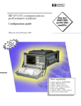
Quick Start Guide HP 37717C Communications Performance Analyzer Copyright HewlettPackard Ltd.1998 Documentation Warranty All rights reserved. Reproduction, adaption, or translation without prior written permission is prohibited, except as allowed under the copyright laws. The information contained in this document is subject to change without notice. HP Part No. 37717-90401 First edition, 03/98 Printed in U.K. Hewlett-Packard makes no warranty of any kind with regard to this material, including, but not limited to, the implied warranties or merchantability and fitness for a particular purpose. Hewlett-Packard shall not be liable for errors contained herein or for incidental or consequential damages in connection with the furnishing, performance, or use of this material. Hewlett-Packard Limited Telecommunications Networks Test Division South Queensferry West Lothian, Scotland EH30 9TG WARNING For details of safety, see Safety information at the front of the Calibration manual. Warning Symbols Used on the Product ! The product is marked with this symbol when the user should refer to the instruction manual in order to protect the apparatus against damage. The product is marked with this symbol to indicate that hazardous voltages are present The product is marked with this symbol to indicate that a laser is fitted. The user should refer to the laser safety information in the Calibration Manual. Quick Start Guide HP 37717C Communications Performance Analyzer About This Book The Quick Start Guide demonstrates the basic operation of the instrument. This guide tells you how to select the displays that you want and how to use them to modify the instrument functions. This guide also tells you about the front panel key functions, the indicators and the connectors. 2 Contents Introduction to the 37717C Front Panel 7 Selecting Displays 8 Selecting Multiple or Single Windows 9 Moving Around Multiple Windows 10 Selecting the Graph or Other Display in Multiple Windows 11 Changing the Displayed Folder 13 Changing the Instrument Settings 14 Modifying Displays with Pop-up Menus 16 Making Selections using Pictorial and Graphic Displays. 20 Using with a Monitor 24 Using the Other Front Panel Keys 25 Monitoring Status 27 Displaying Status History 27 General Alarm Indicators 28 PDH / DSn Alarm Indicators 28 ATM Alarm Indicators 28 Jitter Alarm Indicators 28 SDH Alarm Indicators 29 SONET Alarm Indicators (Option 120) 29 iii Contents iv Getting Started This chapter shows you how to select and change displays Getting Started Getting Started shows you how to select displays and use them to change the instrument settings. Getting started includes the following: • How to select single or multiple windows • How to obtain the required display using the display select keys, TRANSMIT ; RECEIVE ; RESULTS ; GRAPH ; OTHER • How to modify the display information, using and the display softkeys or pop-up menus • How to use the other front panel keys • How to interpret the front panel status indicators • How to connect to external equipment 6 and Getting Started Introduction to the 37717C Front Panel Introduction to the 37717C Front Panel Received signal and alarm condition Select display TRANSMIT FRAME LOSS PATTERN LOSS LOSS OF POINTER ERRORS MS-AIS PDH/DSn AIS RECEIVE RESULTS Start/ stop test RUN/ STOP AU-AIS FRAME LOSS CLOCK LOSS M/F LOSS MS-RDI REMOTE ALARM HP-RDI TU-AIS REMOTE M/F ALARM VP ALARM GRAPH SDH/SONET LOS LP-RDI ATM POINTER ADJUST VC ALARM LOSS OF CELL SYNC HISTORY SELECTED CELL NOT RX SHOW HISTORY JITTER UNLOCK OTHER RESET HISTORY JITTER HITS Manual printer/ logging controls PAPER FEED PRINT NOW SET Control pop up menu Move cursor CANCEL The operator interface is provided by the display and the front panel keys. The display may be multiple windows or a single window. When the display is multiple windows, the "active" window is indicated with a color which is different from the color of the three "inactive" windows. 7 Getting Started Selecting Displays Selecting Displays A multiple window display is available. The displayed pages are: Transmitter Output, Receiver Input, Results and either Graph or Other (Function). TRANSMIT Allows control of the settings associated with the generated signal. RECEIVE Allows control of the settings associated with the received signal. RESULTS Allows control of the test timing and graph storage and displays the selected measurement results. GRAPH Allows management of the stored graphical results. OTHER Allows control of Stored Settings, Settings Control, Floppy Disk, Logging, Remote Control, Time & Date, Miscellaneous (Keyboard Lock, Beep on Received Error, Suspend Test on Signal Loss), Option and Option Enable, Calibration, Autosetup and Color Control. A list of Options fitted is also displayed. 8 Getting Started Selecting Displays Selecting Multiple or Single Windows To select single window, use the display keys TRANSMIT ; RECEIVE ; RESULTS ; GRAPH and OTHER , to select the display required and then press SINGLE WINDOW . Most examples in this manual use SINGLE window. To return to multiple windows, press MULTIPLE WINDOW . Example: To obtain a single window transmit display, Use TRANSMIT to make the transmit window active. 9 Getting Started Selecting Displays Use SINGLE WINDOW to obtain a single transmit window display To change the page displayed in the single window, press the page key for the page required (e.g. RECEIVE, RESULTS, GRAPH or OTHER) . When returning to multiple windows, the current single window display will become the active display within the multiple windows. Moving Around Multiple Windows To move the cursor to another of the displayed windows, press the display selection key for that window. Example: The cursor is in the TRANSMITTER OUTPUT window at the top left of the display. . 10 Getting Started Selecting Displays If you want to make changes to the receive display, you need to make the receive display "active". To move the cursor to the RECEIVER INPUT window at the top right of the display, press RECEIVE . Selecting the Graph or Other Display in Multiple Windows Press OTHER or GRAPH for the display that you want. Example: To change the display from OTHER GRAPH . to GRAPH . Press 11 Getting Started Selecting Displays Display with OTHER FUNCTION Press GRAPH to change to the graph display 12 Getting Started Selecting Displays Changing the Displayed Folder Many windows displayed with the TRANSMIT ; RECEIVE ;and RESULTS keys contain a number of “folders” which may be selected with and . For example, in the display given below there are five “folders” MAIN SETTINGS, STRUCT’D SETTINGS, JITTER and TEST FUNCTION. In this example MAIN SETTINGS is the current selection. Example: To change the PDH display shown from MAIN SETTINGS to STRUCTURED SETTINGS. Use . 13 Getting Started Changing the Instrument Settings Changing the Instrument Settings Settings which may be changed are displayed in a different color to those which are fixed. In this manual, variable settings are shown on the displays in [ ]. In each of the display areas the field currently able to be changed is marked by a highlighted cursor. The highlighted cursor is moved around the display using and . The menu of selections available, for the highlighted field, appears at the bottom of the display: RS232 ; HP IB ; DISK . The choice from the menu is made using the display softkeys situated immediately below the display. When a field has more than five choices, as in SPEED shown here, a softkey labelled MORE is provided. 14 Getting Started Changing the Instrument Settings When MORE is chosen the remainder of the menu is revealed. 15 Getting Started Changing the Instrument Settings Modifying Displays with Pop-up Menus Although the method of modifying the displays with softkeys is always available, it is easier in many cases to use the Pop-up menus. The pop-up menus are particularly useful for: • Text entry • Date/time entry • Integer, Hexadecimal and Binary entry • Trace data entry • Menu selection when there are a large number of choices • SDH/SONET payload mapping • ATM physical and adaptation layer selections • Jitter mask selections If an attempt is made to set out of range values, the instrument will adopt the nearest possible legal value. Text, Trace Data, Date and Time, Integer and Hexadecimal Selection. Move the cursor to the field to be changed. Press SET for the pop-up menu. The current selection is shown in a window at the top of the pop-up menu. To move through the current setting in the window use and to select or . <<< >>> Use SET to move to the required field. 16 Getting Started Changing the Instrument Settings Select the required character or function on the pop-up menu with and . Press SET to set the selection in the window at the top of the pop-up menu. When the required content is displayed in the window at the top of the pop-up menu, select END and press SET to change the instrument setting to the new value. To exit the menu display without making the change, press CANCEL . Example: The pop-up menu provides a more convenient method of entering stored setting titles. Move the cursor into one of the title fields and press SET . SET 17 Getting Started Changing the Instrument Settings Binary Entry For fields which require binary data entry, use SET to display the popup menu. The current setting is shown in a window at the top of the pop-up menu. To move through the selected entry with the pop-up menu use <<< and >>> see page 16. Binary selection is achieved with = 0 and = 1. This operation enters the selected character, 0 or 1, and moves to the next character. This method allows rapid setting of binary words. For example: To set the word 11110011 Use . Selection of the last character changes the instrument setting to the new value. To exit the menu display without making the change, press CANCEL . Example: The binary pop-up menu maybe used to set up a user defined word. In this example the user defined word is an ATM payload background byte. SET 18 Getting Started Changing the Instrument Settings Menu Selection There is a menu selection available as an alternative to any group of soft keys. Display the menu with SET . Use and to make the selection. To change to the new value, press SET . To exit the display without making the change, press CANCEL . Example: SET 19 Getting Started Changing the Instrument Settings Making Selections using Pictorial and Graphic Displays. In some cases selection is simplified with a pictorial or graphic "map" display. This facility is available where the display has a + symbol. These displays are obtained in the same way as the pop-up menus using SET . Some of these displays include menus which allow the settings to be changed. NOTE Details of the pictorial display depend on the optional modules fitted to the instrument. SDH Payload Mapping With the cursor in the MAPPING field, press SET to display the payload map. To change between AU- layer, TU-layer and Payload layer selections, use and . To select the mapping you want, use and . To change to the new value, press SET . To exit the map display without making the change, press CANCEL . .Example: AU-layer SET 20 TU-layer Payload layer Getting Started Changing the Instrument Settings ATM Physical Layer Selections With the cursor in the ATM, PHYSICAL LAYER, SIGNAL field, press SET to display the physical interface. Use and to select the interface you want. To change to the new value, press SET . To exit the map display without making the change, press CANCEL . Example: SET 21 Getting Started Changing the Instrument Settings Jitter Mask Selection Graphical displays of jitter mask selections are available. The current settings are shown by a marker on the graphical display. Jitter Mask set to Off To obtain a graphical display, move the cursor to RANGE, MODULATION FREQUENCY, or AMPLITUDE and press SET . To change a value, use and to select the parameter you want to change, RANGE, MOD FREQ OR AMPLITUDE. Press SET for a pop-up menu. Make your selection from the pop-up menu as described in Modifying Displays with Pop-up Menus page 16 and press SET again to select the new value. The marker on the graphical display will move to the new position and set the new value. To exit the graphical display with the new value set, press CANCEL . SET 22 Getting Started Changing the Instrument Settings Jitter Mask set to Swept To obtain a pictorial display, move the cursor to JITTER MASK [SWEPT] and press SET . The marker moves continuously through the sweep range. To exit the pictorial display use CANCEL . SET To change the frequency, press SET for a pop-up menu. Use and to make your selection from the pop-up menu and press SET again to select the new value To exit the graphical display with the new value set, press CANCEL 23 Getting Started Using with a Monitor Jitter Mask set to Spot To obtain a graphical display, move the cursor to SPOT FREQUENCY and press SET . . SET To change the frequency press SET for a pop-up menu of the values available. Use and to make your selection from the pop-up menu and press SET again to select the new value. The marker on the graphical display will move to the new position and update the value. To exit the graphical display with the new value set, press CANCEL Using with a Monitor For ease of viewing at a distance, the instrument display may be presented on a monitor. The monitor should be connected to the HP 37717C front panel VGA connector. 24 Getting Started Using the Other Front Panel Keys Using the Other Front Panel Keys FRAME LOSS SDH/SONET LOS LOSS OF POINTER PATTERN LOSS MS-AIS ERRORS AIS PDH/DSn AU-AIS LOF CLOCK LOSS M/F LOSS MS-RDI REMOTE ALARM HP-RDI REMOTE M/F ALARM VP ALARM TU-AIS ATM VC ALARM LOSS OF CELL SYNC LP-RDI POINTER ADJUST HISTORY SELECTED CELL NOT RX JITTER UNLOCK JITTER HITS AUTO SETUP The test set attempts to match the settings to the received signal. RUN/STOP Terminates the current test period if one is in progress. Starts a new test period. The indicator above the key is lit when a test period is in progress. SINGLE Adds a single bit error to the output data pattern each time the key is pressed. LOCAL Returns the instrument from remote operation to Local (keyboard) operation. The indicator above the key is lit when the instrument is under Remote Control. SET Displays the pop-up menu for the currently highlighted field. This key also confirms the selection made. CANCEL Clears the pop-up menu without changing the selection. PRINT NOW The selected measurement results are logged, immediately, to the selected printer. PAPER FEED The paper in the internal printer is advanced. 25 Getting Started Using the Other Front Panel Keys CAUTION Do not press PAPER FEED while attempting to load a new roll of paper in the printer. It could result in a paper jam and disable the printer. Wait until the paper is fed through the printer mechanism before pressing PAPER FEED . 26 Getting Started Monitoring Status Monitoring Status LOSS FRAME LOSS SDH/SONET PATTERN LOSS LOSS OF POINTER ERRORS AIS MS-AIS PDH/DSn AU-AIS FRAME LOSS CLOCK LOSS M/FRAME LOSS MS-RDI REMOTE ALARM HP-RDI REMOTE M/FRAME ALARM TU-AIS VP ALARM ATM VC ALARM LP-RDI POINTER ADJUST LOSS OF CELLSYNC SELECTED CELL NOT RX JITTER UNLOCK JITTER HITS Displaying Status History The Status indicators on the front panel convey information regarding the current status of the instrument. If an alarm has occurred during the current Test Period, the indicator above SHOW HISTORY is lit. To view which alarms have occurred, press and hold SHOW HISTORY . When SHOW HISTORY is released the status indicators return to displaying the current status. SHOW HISTORY When pressed and held, the Status indicators display any alarms which have been set during the current Test Period. This continues until SHOW HISTORY is released at which time the current status is displayed. The indicator above the key is lit to signify that an alarm has occurred during the current Test Period. RESET HISTORY Resets the history store such that the historical and present status are the same. This can also be achieved by starting a new Test Period. 27 Getting Started Monitoring Status General Alarm Indicators Loss No data transitions at the input port. Pattern Loss The received data pattern is not in synchronization with the internally generated reference data. Errors A measured error has occurred. The indicator will remain lit for 100 ms. PDH / DSn Alarm Indicators These are active when a PDH / DSn signal is received AIS The All Ones AIS signal is detectable in the presence of a 1 in 10-3 error rate. Frame Loss Frame alignment lost or out of alignment condition. M/Frame Loss Multiframe alignment lost. Remote Alarm Remote alarm, x-bit or yellow alarm bit is set. Remote M/ Frame Alarm Remote Multiframe Alarm bit is set. ATM Alarm Indicators These are active when an ATM signal is received. VP Alarm Virtual Path AIS or FERF has been detected. VC Alarm Virtual Channel AIS or FERF has been detected. Loss of Cell Sync Cell Sync Loss has been detected. Selected Cell Not RX The selected cell has not been received.Selected cell not received. Jitter Alarm Indicators Jitter Unlock The jitter receiver has lost phase lock. Jitter measurement is suspended until lock is regained. Jitter Hits A jitter hit has been detected. 28 Getting Started Monitoring Status SDH Alarm Indicators These are active when an SDH signal is received. FRAME LOSS Loss Of Frame has been detected. LOSS OF POINTER Loss of pointer has been detected. MS-AIS Multiplexer Section AIS has been detected. AU-AIS Path AIS has been detected. CLOCK LOSS The transmitter clock is not synchronized to the selected reference. MS-RDI Multiplexer Section RDI (FERF) has been detected. HP-RDI Path RDI (FERF) has been detected. TU-AIS TU Path AIS has been detected. . LP-RDI TU Path RDI (FERF) has been detected. . POINTER ADJUST A pointer change in the foreground signal has been detected. SONET Alarm Indicators (Option 120) These are active when a SONET signal is received. LOF/SEF Loss of Frame or Severely Errored Frame has been detected. Status message on bottom of display states which has occurred. LOP-P/LOP-V Loss of Pointer has been detected. AIS-L Line AIS has been detected. AIS-P STS Path AIS has been detected. CLOCK LOSS The transmitter clock is not synchronized to the selected reference. RDI-L Line Remote Defect Indication (RDI) has been detected. RDI-P STS Path RDI has been detected. AIS-V Virtual Tributary path AIS has been detected. 29 Getting Started Monitoring Status RDI-V POINTER ADJUST 30 VT path RDI has been detected. A pointer change in the foreground signal has been detected. Index A AIS alarm indicator, 28 Alarm Indicator AIS, 28 Errors, 28 Frame loss, 28 HP-RDI, 29 Jitter unlock, 28 LOF/OOF, 29 Loss of cell sync, 28 LP-RDI, 29 M/Frame loss, 28 MS-RDI, 29 Pattern Loss, 28 Pointer adjust, 29 Remote alarm, 28 Remote M/frame alarm, 28 Selected cell not received, 28 Signal Loss, 28 TU-AIS, 29 TU-LOP, 29 VC Alarm, 28 VP alarm, 28 Alarm Indicators ATM, 28 General, 28 Jitter hits, 28 PDH / DSn, 28 SDH, 29 ATM Alarm Indicators, 28 ATM Alarms Loss of Cell Sync, 28 Selected Cell Not Received, 28 VC Alarm, 28 VP Alarm, 28 ATM layer selections with pop-up menus, 21 AU-AIS Alarm IndicatorAlarm Indicator AU-AIS, 29 Auto Setup key, 25 B Binary entry with pop-up menu, 18 C Cancel key, 25 Changing settings on displays, 14 Changing settings with soft keys, 14 Clock Loss Alarm IndicatorAlarm Indicator Clock loss, 29 Cursor Introduction to, 14 Moving, 14 D Date and time entry with pop-up menu, 16 Display on a monitor, 24 Displaying list of, 8 Displays Changing settings on, 14 DSn Alarm Indicators, 28 E Errors Alarm Indicator, 28 F Folder Selecting, 13 Frame Loss Alarm Indicator, 28 Other, 8 Paper Feed, 25 Print Now, 25 Receive, 8 Reset History, 27 Results, 8 Run / Stop, 25 Set, 25 Show History, 27 Transmit, 8 L Local key, 25 LOF alarm indicator, 29 Loss of Cell Sync Alarm Indicator, 28 Loss Of Pointer Alarm IndicatorAlarm Indicator AU-LOP, 29 LP-RDI Alarm Indicator, 29 H Hexadecimal entry with pop-up menu, 16 History Keys, 27 HP-RDI Alarm Indicator, 29 M M/Fame Loss Alarm Indicator, 28 Menus, pop-up, obtaining, 16 Monitor,connecting, 24 MS-AIS Alarm IndicatorAlarm Indicator MS-AIS, 29 MS-RDI Alarm Indicator, 29 Multiple windows Moving between, 10 Selecting the undisplayed window, 11 Multiple/single window selection, 9 I Indicators Front Panel, 28 Integer entry with pop-up menu, 16 O OOF alarm Indicator, 29 Options fitted, 8 Other key, 8 J Jitter Alarm Indicators, 28 Jitter hits alarm indicator, 28 Jitter Unlock alarm indicator, 28 P Paper Feed key, 25 Pattern Loss Alarm Indicator, 28 PDH / DSn Alarms AIS, 28 Frame Loss, 28 M/Frame Loss, 28 Remote Alarm, 28 Remote M/Frame Alarm, 28 PDH Alarm Indicators, 28 Pictorial displays as a selection aid, 20 G Graph key, 8 Graphic displays as a selection aid, 20 K Keys Auto Setup, 25 Cancel, 25 Graph, 8 Local, 25 31 Index Pointer Adjust Indicator, 29 Pop-up menus As alternative to soft keys, 19 Modifying displays with, 16 Print Now key, 25 R Receive key, 8 Remote Alarm Indicator, 28 Remote M/Frame Alarm Indicator, 28 Reset History key, 27 Results key, 8 Run / Stop Key, 25 S SDH Alarm Indicators, 29 SDH Alarms AU-AIS, 29 Clock Loss, 29 HP-RDI, 29 Loss Of Pointer, 29 LP-RDI, 29 MS-AIS, 29 MS-RDI, 29 Pointer Adjust, 29 TU-AIS, 29 SDH payload mapping with pictorial display, 20 Selectable display values, 15 Selected Cell Not Received Alarm Indicator, 28 Set key, 25 Settings changing with soft keys, 14 Show History key, 27 Signal Loss Alarm Indicator, 28 Single/multiple window selection, 9 Soft key alternative, pop-up menu, 19 Soft keys using, 14 Status Indicators, 27 T Text entry with pop-up menu, 16 Trace data entry with pop-up menu, 16 Transmit key, 8 TU-AIS Alarm Indicator, 29 32 V VC Alarm Indicator, 28 VP Alarm Indicator, 28 Hewlett-Packard Sales and Service Offices If you need technical assistance with a Hewlett-Packard test and measurement product or application please contact the Hewlett-Packard office or distributor in your country. Asia Pacific: Hong Kong: Tel: (852) 2599 7889 India: Tel: (91-11) 682-6000 Japan: Hewlett-Packard Japan Ltd. Measurement Assistance Center 9-1, Takakura-Cho, Hachioji-Shi, Tokyo 192-8510, Japan Tel: (81) 426-56-7832 Fax: (81) 426-56-7840 Korea: Tel: (82-2) 769 0800 For countries in Asia Pacific not listed, contact: Hewlett-Packard Asia Pacific Ltd 17-21/F Shell Tower, Times Square, 1 Matheson Street Causeway Bay Hong Kong Tel: (852) 2599 7777 Fax: (852) 2506 9285 Australia/New Zealand: Hewlett-Packard Australia Ltd. 31-41 Joseph Street Blackburn, Victoria 3130 Australia Tel: 1 800 629 485 Canada: Hewlett-Packard Canada Ltd. 5150 Spectrum Way Mississauga, Ontario L4W 5G1 Tel: (905) 206 4725 Malaysia: Tel: (60-3) 291 0213 Europe, Africa and Middle East: Philippines: Tel: (63-2) 894 1451 Austria: Tel: (0)1 25000-0 People’s Republic of China: Tel: (86-10) 6505 0149 Singapore: Tel: (1800) 292 8100 Taiwan: Tel: (886-3) 492 9666 Thailand: Tel: (66-2) 661 3900 Belgium and Luxembourg: Tel: (02) 778 3417 Baltic Countries: Tel: (358) 08872 2100 Czech Republic: Tel: 420-2-4743111 Denmark: Tel: 45 99 10 00 Hewlett-Packard Sales and Service Offices (cont’d) Finland: Tel: (90) 88 721 France: Tel: (0)1 69.82.60.60 Germany: Tel: (0180) 532 62-33 Greece: Tel: 30-1-7264045 Hungary: Tel: 36-1-4618219 Ireland: Tel: (01) 284 4633 Israel: Tel: 972-3-5380333 Italy: Tel: 02 - 92 122 241 Netherlands: Tel: (020) 547 6669 Norway: Tel: (22) 73 57 50 Poland: Tel: 48-22-6087700 Portugal: Tel: (11) 482 85 00 Russia: Tel: (7/095) 928 6885 Fax: (7/095) 916 9844 South Africa: Tel: 27-22-8061000 Spain: Tel: (34) 1 631 1323 Sweden: Tel: (08) 444 22 77 Switzerland: Tel: (01) 735 7111 Turkey: Tel: 90-212-2245925 United Kingdom: Tel: (01344) 366 666 For countries in Europe/Middle East and Africa not listed, contact: Hewlett-Packard International Sales Europe Geneva, Switzerland Tel: +41-22-780-4111 Fax: +41-22-780-4770 Latin America: Hewlett-Packard Latin American Region Headquarters 5200 Blue Lagoon Drive 9th Floor Miami, Florida 33126 U.S.A. Tel: (305) 267-4245 Tel: (305) 267-4220 Fax: (305) 267-4288 United States: Hewlett-Packard Company Test and Measurement Organization 5301 Stevens Creek Blvd. Bldg. 51L-SC Santa Clara, CA 95052-8059 Tel: 1 800 452 4844 About This Edition This is the 1st edition of the 37717-90401 manual. It documents the product as of March 1998. Edition dates are as follows: 1st Edition, March 1998 Copyright HewlettPackard Ltd. 1998. All rights reserved. Reproduction, adaption, or translation without prior written permission is prohibited, except as allowed under the copyright laws. In This Book This book demonstrates the basic operation of the instrument. It tells you how to select the displays that you want and how to use them to modify the instrument functions. This guide also tells you about the front panel key functions, the indicators and the connectors. Printed in U.K. 03/98 37717-90401