1
HP StorageWorks
Enterprise Virtual Array Cluster Administrator
Guide
This guide provides information for a storage administrator on how to manage the HP StorageWorks EVA
Cluster.
Part Number: 5697–0517
First edition: June 2010
Legal and notice information
© Copyright 2010 Hewlett-Packard Development Company, L.P.
Confidential computer software. Valid license from HP required for possession, use or copying. Consistent with FAR 12.211
and 12.212, Commercial Computer Software, Computer Software Documentation, and Technical Data for Commercial Items
are licensed to the U.S. Government under vendor's standard commercial license.
The information contained herein is subject to change without notice. The only warranties for HP products and services are set
forth in the express warranty statements accompanying such products and services. Nothing herein should be construed as
constituting an additional warranty. HP shall not be liable for technical or editorial errors or omissions contained herein.
Acknowledgements
Microsoft® and Windows® are U.S. registered trademarks of Microsoft Corporation.
Warranty
WARRANTY STATEMENT: To obtain a copy of the warranty for this product, see the warranty information website:
http://www.hp.com/go/storagewarranty
Revision History
Revision History
Revision 1.0
Initial release
June 2010
Contents
1 HP EVA Cluster overview ................................................................... 13
Hardware ................................................................................................................................
Enterprise Virtual Arrays ......................................................................................................
Data Path Modules .............................................................................................................
VSM server .......................................................................................................................
Management servers ..........................................................................................................
Fibre Channel switches ........................................................................................................
Ethernet switch ...................................................................................................................
Software ..................................................................................................................................
Virtualization Services Manager ...........................................................................................
Data Path Module software .................................................................................................
HP Command View EVA .....................................................................................................
HP Command View SVSP ....................................................................................................
Licenses ...................................................................................................................................
Installing a license key file ...................................................................................................
Viewing licensed capacity ...................................................................................................
14
14
15
15
15
15
15
15
15
16
16
16
16
17
18
2 Adding servers to the HP EVA Cluster ................................................. 21
Zoning ....................................................................................................................................
Adding new servers ..................................................................................................................
Upgrading the AIX operating system .....................................................................................
VMware ESX Server ...........................................................................................................
Aligning file system partitions for Windows (pre-2008) ............................................................
Installing multipath applications ...........................................................................................
AIX multipathing ..........................................................................................................
HP-UX multipathing ......................................................................................................
Linux multipathing ........................................................................................................
OpenVMS multipathing ................................................................................................
Solaris 9 multipathing ..................................................................................................
Solaris 10 multipathing ................................................................................................
VMware multipathing ...................................................................................................
Windows multipathing .................................................................................................
Presenting SVSP virtual disks to servers ..................................................................................
Creating the user defined host (UDH) .............................................................................
Creating VSM virtual disks ............................................................................................
Defining hosts in SVSP ..................................................................................................
21
21
21
23
23
25
25
26
26
27
27
27
28
28
30
30
30
31
3 Zoning ........................................................................................... 33
Zoning overview .......................................................................................................................
HP SVSP zoning principles .........................................................................................................
Zoning components in HP SVSP ..................................................................................................
Dual-fabric device configuration .................................................................................................
DPM-host zoning .......................................................................................................................
DPM-storage zoning ..................................................................................................................
Enterprise Virtual Array Cluster Administrator Guide
33
34
35
37
38
40
3
DPM-VSM zoning ..................................................................................................................... 42
VSM-storage zoning .................................................................................................................. 43
VSM-VSM zoning ..................................................................................................................... 44
4 HP StorageWorks Management Infrastructure ...................................... 45
Quick tours ..............................................................................................................................
Configuration interface – details page quick tour ....................................................................
Configuration interface – registry page quick tour ...................................................................
Security interface – Management Group page quick tour ........................................................
Security interface – Move Machine wizard quick tour ..............................................................
Management Infrastructure concepts ............................................................................................
Discovery ..........................................................................................................................
Security integration .............................................................................................................
User interface integration (SPoG and trees) ............................................................................
Applications (Management Infrastructure specific) ...................................................................
Authenticators (Management Infrastructure specific) .................................................................
Configuration settings and service startup ..............................................................................
Interface server (Management Infrastructure specific) ...............................................................
Log in user names ..............................................................................................................
OS security domains ...........................................................................................................
Registry (Management Infrastructure specific) .........................................................................
Management Group security certificates ................................................................................
Service (Management Infrastructure specific) ..........................................................................
Management Groups ..........................................................................................................
Management Group names .................................................................................................
Web services (Management Infrastructure specific) .................................................................
Management Group machines .............................................................................................
Installing Management Group security certificates .........................................................................
Management Group security certificate installation overview ....................................................
Installing Management Group security certificates in Internet Explorer 6.0 ...........................
Installing Management Group security certificates in Internet Explorer 7.0 and 8.0 ...............
Installing Management Group security certificates in Mozilla Firefox 3.0 .............................
Configuring Windows Server 2008 IE ESC .....................................................................
Using the configuration interface .................................................................................................
Best practices ....................................................................................................................
Changing a machine's configuration ....................................................................................
Configuring a multi-home machine .......................................................................................
Using keyboard navigation ..................................................................................................
Logging in to the configuration interface ................................................................................
Restarting the Management Infrastructure service ....................................................................
Restoring the default configuration for a machine ....................................................................
Viewing configuration guidelines ..........................................................................................
Viewing the configuration for a machine ...............................................................................
Configuration settings ................................................................................................................
Configuration settings overview ............................................................................................
General configuration settings ..............................................................................................
Audit file max age .......................................................................................................
Audit file max size .......................................................................................................
Configurator port .........................................................................................................
Log file max age ..........................................................................................................
Log file max size ..........................................................................................................
Logging level ...............................................................................................................
Web server connections ...............................................................................................
Web server port ..........................................................................................................
4
45
45
46
47
47
48
48
48
49
49
49
50
50
50
50
50
50
51
51
54
54
54
54
54
55
56
56
57
58
58
58
58
59
59
60
60
61
61
61
61
62
62
62
62
62
62
63
63
63
Web service IP address (IPv4/IPv6) ................................................................................
Discovery configuration settings ...........................................................................................
Discovery interval ........................................................................................................
Discovery URI ..............................................................................................................
Management port ........................................................................................................
Non-local registry entry time-out ....................................................................................
Registry port ...............................................................................................................
Registry table updates ..................................................................................................
Registry update address (IPv4/IPv6) ...............................................................................
Security configuration settings ..............................................................................................
Available OS security domains ......................................................................................
Local service port .........................................................................................................
Login service port ........................................................................................................
Management Group communication service port .............................................................
Management Group management service port ................................................................
Tree integrator configuration settings .....................................................................................
Decorator age time-out .................................................................................................
Discover new tree interval .............................................................................................
SPoG port ...................................................................................................................
SPoG time-out .............................................................................................................
Tree age time-out .........................................................................................................
Tree decorator port ......................................................................................................
Tree integrator port ......................................................................................................
Using the security interface ........................................................................................................
Adding a machine to a Management Group .........................................................................
Creating a Management Group ...........................................................................................
Deleting a Management Group ...........................................................................................
Logging in to the security interface .......................................................................................
Removing a machine from a Management Group ...................................................................
Renaming a Management Group .........................................................................................
Using keyboard navigation ..................................................................................................
Troubleshooting .................................................................................................................
Installation ..................................................................................................................
Management Group change troubleshooting ...................................................................
63
64
64
64
64
65
65
65
65
66
66
66
66
67
67
67
67
67
68
68
68
68
69
69
69
69
70
70
70
71
71
72
72
72
5 Monitoring the SVSP domain ............................................................. 75
Array workload concentration ....................................................................................................
Monitoring system performance ..................................................................................................
System health monitoring .....................................................................................................
HP Command View SVSP GUI .......................................................................................
HP Command View SVSP Event Log ...............................................................................
Alerts automated notification .........................................................................................
Setting up Perfmon .............................................................................................................
Using Perfmon counters to log ..............................................................................................
Troubleshooting Perfmon .....................................................................................................
Monitoring access to the VSM setup volume .................................................................................
Description of the VSM setup volume ....................................................................................
Using Performance Monitor to review setup volume access times ...............................................
Recommendations ..............................................................................................................
Monitoring DPM performance ....................................................................................................
Monitoring license use ...............................................................................................................
Monitoring capacity utilization ...................................................................................................
Monitoring event logs ................................................................................................................
Monitoring the SAN ..................................................................................................................
Enterprise Virtual Array Cluster Administrator Guide
75
75
75
76
77
77
78
80
81
81
81
81
84
84
85
85
85
85
5
Pool monitoring ........................................................................................................................
Global mechanisms ............................................................................................................
Individual mechanisms ........................................................................................................
Percentage on an individual virtual disk ..........................................................................
PiT capacity planning ...................................................................................................
85
85
86
86
86
6 Installing the VSM command line interface .......................................... 87
Creating the VSM CLI virtual disk ................................................................................................ 87
Install the appropriate VSM CLI package for the host operating system ............................................ 87
7 Removing devices from the domain ..................................................... 89
Deleting or reusing capacity .......................................................................................................
Deleting PiTs, snapshots, pools, and stripe sets .......................................................................
Deleting back-end LUs .........................................................................................................
Deleting front-end virtual disks and hosts ...............................................................................
Retiring an array .......................................................................................................................
Deleting hosts ...........................................................................................................................
89
89
90
90
90
91
8 Boot from SVSP devices .................................................................... 93
Boot
Boot
Boot
Boot
Boot
Boot
Boot
from SAN with AIX ............................................................................................................
from SAN with HP-UX .........................................................................................................
from SAN with Linux ..........................................................................................................
from SAN with OpenVMS ..................................................................................................
from SAN with Solaris ........................................................................................................
from SAN with VMware .....................................................................................................
from SAN with Windows Server ..........................................................................................
93
93
94
94
94
94
95
9 Microsoft Volume Shadow Copy Service ............................................. 97
The VSS model ......................................................................................................................... 97
Installing and configuring Microsoft VSS with VSM virtual disks ...................................................... 98
Installing the SVSP VSS hardware provider on the host server ................................................... 98
Making sure that VSS works with the VSM virtual disks ......................................................... 102
Integrating VSS with asynchronously mirrored VSM virtual disks ............................................. 105
Integrating VSS with backup software ................................................................................. 105
VSS deployment with VSM virtual disk groups ...................................................................... 108
Uninstalling the SVSP VSS hardware provider ...................................................................... 109
10 Site failover recovery with asynchronous mirrors ............................... 111
The asynchronous mirror decision table ......................................................................................
Establishing a disaster recovery site ...........................................................................................
Testing or validating your ability to recover from a DR site without detaching or splitting the async
mirror group ..........................................................................................................................
Testing a DR site or switching between sites ................................................................................
Failing over to the DR site and back to the main site after a problem .............................................
Failing over to a disaster recovery site when the main site is totally lost ..........................................
111
113
114
114
115
116
11 Configuration best practices .......................................................... 119
SAN topology ........................................................................................................................
Redundant fabrics from the servers to the EVA Cluster ............................................................
SAN switches ..................................................................................................................
Fibre Channel links ...........................................................................................................
Mixing SAN-level virtualization with non-virtualized environments ...........................................
6
119
119
120
120
120
Setup volume configuration ......................................................................................................
Building basic storage pools ....................................................................................................
Building storage pools using stripe sets ...............................................................................
Storage pool size considerations ........................................................................................
Using thinly provisioned virtual disks .........................................................................................
120
121
122
123
123
12 Backup and restore ...................................................................... 125
Backing up and restoring the VSM configuration ......................................................................... 125
Backing up and restoring the DPM configuration ......................................................................... 126
13 Basic maintenance and troubleshooting .......................................... 129
Diagnostic tools ......................................................................................................................
Fault isolation .........................................................................................................................
Startup problems ..............................................................................................................
Configuration problems .....................................................................................................
Presentation problems .......................................................................................................
Administrative problems ....................................................................................................
Zoning verification ............................................................................................................
VSM server zoning ....................................................................................................
DPM zoning ..............................................................................................................
VSM server LUN masking ...........................................................................................
DPM LUN masking .....................................................................................................
129
129
129
130
132
133
133
133
133
134
134
14 Support and other resources .......................................................... 135
Contacting HP ........................................................................................................................
Subscription service ..........................................................................................................
Submitting an SaSnap or faxing a health check to HP Support .....................................................
Creating and submitting an SaSnap ...................................................................................
Print and fax health check commands .................................................................................
Related information .................................................................................................................
HP websites .....................................................................................................................
Typographic conventions .........................................................................................................
Rack stability ..........................................................................................................................
HP product documentation survey .............................................................................................
135
135
135
135
139
140
140
140
141
142
A Using VSM with firewalls ................................................................ 143
Windows 2003 ...................................................................................................................... 143
Windows 2008 ...................................................................................................................... 146
B Adding arrays to the EVA Cluster ..................................................... 151
Adding a new array ...............................................................................................................
Adding EVAs ...................................................................................................................
Adding MSAs ..................................................................................................................
Adding HP XP arrays ........................................................................................................
Adding non-HP branded arrays ..........................................................................................
Adding new back-end logical units from non-HP arrays .........................................................
151
152
152
154
155
155
C Deploying VMware ESX Server with SVSP ......................................... 157
Deployment overview ..............................................................................................................
Deployment steps .............................................................................................................
Supported VMware ESX versions ........................................................................................
Supported VSM software versions ......................................................................................
Enterprise Virtual Array Cluster Administrator Guide
157
158
158
158
7
Importing the VMware datastore ........................................................................................
Configuration .........................................................................................................................
Fibre Channel zoning .......................................................................................................
Storage system .................................................................................................................
HP Command View SVSP GUI ...........................................................................................
VMware ESX server ..........................................................................................................
VMware storage administration best practices ............................................................................
Rescan SAN operations ....................................................................................................
Storage VMotion ..............................................................................................................
Using VSS with Windows 2003 SP2 running on a virtual machine .........................................
Creating synchronized snapshots of application volumes .................................................
Creating a synchronized snapshot of the virtual machine ................................................
N-port ID virtualization (NPIV) ............................................................................................
Microsoft cluster ...............................................................................................................
Installing and booting an VMware ESX server from the SAN ..................................................
VMware issues .......................................................................................................................
VMware and large I/Os ...................................................................................................
Using Windows Guests on VMware with VSS ......................................................................
158
159
159
159
159
160
163
163
163
163
163
164
164
164
164
165
165
166
D Configuration worksheets ................................................................ 167
E Specifications ................................................................................ 169
Data Path Module ...................................................................................................................
Characteristics .................................................................................................................
Media ............................................................................................................................
High availability features ...................................................................................................
Management standards ....................................................................................................
Device management .........................................................................................................
Mechanical .....................................................................................................................
Environmental ..................................................................................................................
Electrical .........................................................................................................................
Regulatory .......................................................................................................................
VSM server ............................................................................................................................
Environmental ..................................................................................................................
Mechanical and electrical .................................................................................................
Characteristics .................................................................................................................
169
169
169
169
169
170
170
170
170
171
171
171
171
172
F Regulatory compliance notices ......................................................... 173
Regulatory compliance identification numbers ............................................................................
Federal Communications Commission notice ..............................................................................
FCC rating label ..............................................................................................................
Class A equipment .....................................................................................................
Class B equipment .....................................................................................................
Declaration of Conformity for products marked with the FCC logo, United States only ...............
Modification ....................................................................................................................
Cables ............................................................................................................................
Canadian notice (Avis Canadien) .............................................................................................
Class A equipment ...........................................................................................................
Class B equipment ............................................................................................................
European Union notice ............................................................................................................
Japanese notices ....................................................................................................................
Japanese VCCI-A notice ....................................................................................................
Japanese VCCI-B notice ....................................................................................................
8
173
173
173
173
174
174
174
174
174
174
175
175
175
175
175
Japanese VCCI marking ....................................................................................................
Japanese power cord statement ..........................................................................................
Korean notices .......................................................................................................................
Class A equipment ...........................................................................................................
Class B equipment ............................................................................................................
Taiwanese notices ...................................................................................................................
BSMI Class A notice .........................................................................................................
Taiwan battery recycle statement ........................................................................................
Turkish recycling notice ............................................................................................................
Laser compliance notices .........................................................................................................
English laser notice ...........................................................................................................
Dutch laser notice .............................................................................................................
French laser notice ...........................................................................................................
German laser notice .........................................................................................................
Italian laser notice ............................................................................................................
Japanese laser notice ........................................................................................................
Spanish laser notice .........................................................................................................
Recycling notices ....................................................................................................................
English recycling notice .....................................................................................................
Bulgarian recycling notice .................................................................................................
Czech recycling notice ......................................................................................................
Danish recycling notice .....................................................................................................
Dutch recycling notice .......................................................................................................
Estonian recycling notice ...................................................................................................
Finnish recycling notice .....................................................................................................
French recycling notice ......................................................................................................
German recycling notice ...................................................................................................
Greek recycling notice ......................................................................................................
Hungarian recycling notice ................................................................................................
Italian recycling notice ......................................................................................................
Latvian recycling notice .....................................................................................................
Lithuanian recycling notice .................................................................................................
Polish recycling notice .......................................................................................................
Portuguese recycling notice ................................................................................................
Romanian recycling notice .................................................................................................
Slovak recycling notice ......................................................................................................
Spanish recycling notice ....................................................................................................
Swedish recycling notice ...................................................................................................
Recycling notices ....................................................................................................................
English recycling notice .....................................................................................................
Bulgarian recycling notice .................................................................................................
Czech recycling notice ......................................................................................................
Danish recycling notice .....................................................................................................
Dutch recycling notice .......................................................................................................
Estonian recycling notice ...................................................................................................
Finnish recycling notice .....................................................................................................
French recycling notice ......................................................................................................
German recycling notice ...................................................................................................
Greek recycling notice ......................................................................................................
Hungarian recycling notice ................................................................................................
Italian recycling notice ......................................................................................................
Latvian recycling notice .....................................................................................................
Lithuanian recycling notice .................................................................................................
Polish recycling notice .......................................................................................................
Portuguese recycling notice ................................................................................................
Enterprise Virtual Array Cluster Administrator Guide
175
176
176
176
176
176
176
177
177
178
178
178
179
179
179
180
180
180
180
181
181
181
181
182
182
182
182
183
183
183
183
184
184
184
184
185
185
185
185
185
186
186
186
187
187
187
188
188
188
189
189
189
190
190
190
9
Romanian recycling notice .................................................................................................
Slovak recycling notice ......................................................................................................
Spanish recycling notice ....................................................................................................
Swedish recycling notice ...................................................................................................
Battery replacement notices ......................................................................................................
Dutch battery notice ..........................................................................................................
French battery notice ........................................................................................................
German battery notice ......................................................................................................
Italian battery notice .........................................................................................................
Japanese battery notice ....................................................................................................
Spanish battery notice ......................................................................................................
191
191
191
192
192
192
193
193
194
194
195
Glossary .......................................................................................... 197
Index ............................................................................................... 205
10
Figures
1 Racked EVA Cluster ................................................................................................. 14
2 Install/Restore License Key screen of the Launch AutoPass window ................................. 18
3 License dialog box .................................................................................................. 18
4 Five zone types ....................................................................................................... 36
5 Dual-fabric port configuration for 4–port and 8–port dual-controller back-end storage
devices .................................................................................................................. 37
6 DPM dual-fabric port configuration ............................................................................ 37
7 Single VSM dual-port configuration ........................................................................... 38
8 Host server dual-port configuration ............................................................................ 38
9 Zoning from server to two quads of a DPM pair .......................................................... 39
10 Zoning between two servers and two quads of a DPM pair .......................................... 39
11 Zoning between two servers with two HBAs and two quads of a DPM pair ..................... 40
12 Zoning between 2 dual-port controllers and first quad of each DPM .............................. 41
13 Zoning between 2 quad-port controllers and two quads of each DPM ............................ 41
14 Zoning between VSMs and first quad of a DPM pair ................................................... 43
15 Zoning between VSMs and two dual-port back-end controllers ...................................... 43
16 Zoning between two VSMs ...................................................................................... 44
17 HP Command View GUI showing status of normal and present ..................................... 76
18 SVSP VSS hardware provider in a DOS window ....................................................... 101
19 Commands supported by the Provider Configuration tool ........................................... 101
20 Results of the vshadow.exe -p m: command in the DOS command prompt window ........ 104
21 Hierarchical snapshot structure ................................................................................ 104
22 Veritas NetBackup software using VSS snapshots ...................................................... 106
23 Example of a disk drive acting as a media server ...................................................... 107
24 Backup policy attributes ......................................................................................... 108
25 VSS selected as the snapshot method ...................................................................... 108
Enterprise Virtual Array Cluster Administrator Guide
11
Tables
1 VSM license types ................................................................................................... 17
2 License capacities ................................................................................................... 19
3 Example naming convention for zone types ................................................................ 36
4 Example naming convention for device port types ....................................................... 36
5 Troubleshooting Perfmon .......................................................................................... 81
6 Fault isolation to a specific area .............................................................................. 129
7 Startup problems .................................................................................................. 129
8 Configuration problems ......................................................................................... 130
9 Presentation problems ............................................................................................ 132
10 Administrative problems ......................................................................................... 133
11 Document conventions ........................................................................................... 140
12
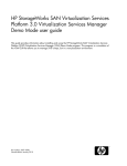
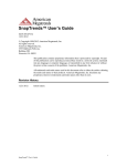
1 HP EVA Cluster overview
The Enterprise Virtual Array (EVA) Cluster is rack installed at the factory and set up on site by HP
Services. Two EVA6400s or EVA8400s are bundled with SAN Virtualization Services Platform (SVSP)
components, software, and licenses, to allow quick deployment into a storage area network. Figure
1 shows a configuration of EVAs with the maximum number of drive shelves available with an optional
expansion cabinet, as well as SVSP devices and Fibre Channel switches.
Enterprise Virtual Array Cluster Administrator Guide
13
1
HP Command View server
5
Ethernet switch
2
VSM server
6
EVA
3
Data Path Module
7
Expansion cabinet (optional)
4
Fibre Channel switch
Figure 1 Racked EVA Cluster
.
Hardware
This section describes the HP EVA Cluster hardware components.
Enterprise Virtual Arrays
The two rack-mounted EVA6400/8400s consist of the following:
• HSV controllers—These contain power supplies, cache batteries, fans, and an operator control
panel (OCP).
14
HP EVA Cluster overview
• Fibre Channel disk enclosures—Contains up to 12 disk drives, power supplies, fans, midplane,
and I/O modules.
• Fibre Channel Arbitrated Loop Cables—Provides connectivity to the HSV controllers and the Fibre
Channel disk enclosures.
For information on the EVAs, go to http://www.hp.com/support/manuals. In the Storage section,
click Disk Storage Systems, and in the EVA Disk Arrays section, click HP StorageWorks 6400/8400
Enterprise Virtual Array.
Data Path Modules
One way to think of the pair of DPMs is as being similar to a pair of array controllers, only with eight
host ports and eight back-end ports per controller. The even ports on the DPMs are the SCSI/FCP
targets for all I/O requests initiated by your application servers. The odd ports of the DPMs act as
the SCSI/FCP initiators to the array host port targets. The DPMs are in an active-passive relationship,
meaning that an individual virtual disk is active on one DPM and on standby on the other DPM within
the DPM group. Therefore, it is beneficial to balance the workload of your disks between the DPMs.
VSM server
The VSM server hosts the Virtualization Services Manager (VSM) software and other special
applications. The reason for the custom server configuration is due to other (and less visible) functions
performed by VSM. For more information, see the HP StorageWorks Virtualization Services Manager
v2 Server User Guide. This and other SVSP documentation can be obtained by going to http://
www.hp.com/support/manuals. In the Storage section, click Storage Software, and in the Storage
Virtualization Software section, click HP StorageWorks SAN Virtualization Services Platform.
Management servers
Two management servers are needed with the EVA Cluster. One hosts the HP Command View EVA
management software and the other hosts the HP Command View SVSP management software.
Fibre Channel switches
Two B-series switches are provided to interconnect the EVA Cluster components.
Ethernet switch
One Ethernet switch is required to connect the EVA Cluster components.
Software
This section describes the HP EVA Cluster software and firmware required.
Virtualization Services Manager
The VSM application runs on each VSM server so that both can perform the data replication tasks.
One VSM performs management and configuration tasks and the other VSM acts as a hot standby
for these tasks:
• Data import
Enterprise Virtual Array Cluster Administrator Guide
15
• Data migration
• Local replication (point-in-time copies, snapshots, and snapclones)
• Asynchronous remote replication
A command line interface (CLI) can be used with the VSM application to write scripts for automated
processes. For information on using the CLI, see the HP StorageWorks SAN Virtualization Services
Platform Manager Command Line Interface User Guide. This and other SVSP documentation can be
obtained by going to http://www.hp.com/support/manuals. In the Storage section, click Storage
Software, and in the Storage Virtualization Software section, click HP StorageWorks SAN Virtualization
Services Platform.
Data Path Module software
The firmware and a command line interface are preinstalled on the Data Path Modules. For DPM GUI
and CLI information, see the HP StorageWorks SAN Virtualization Services Platform Data Path Module
User Guide by going to http://www.hp.com/support/manuals. In the Storage section, click Storage
Software, and in the Storage Virtualization Software section, click HP StorageWorks SAN Virtualization
Services Platform.
HP Command View EVA
HP Command View EVA is the management GUI for the Enterprise Virtual Arrays that prepares the
storage arrays for initial configuration and subsequent management and monitoring. HP Command
View EVA must be installed on a separate management server. For more information, go to http://
www.hp.com/support/manuals. In the Storage section, click Storage Software, and in the Storage
Device Management Software section, click HP StorageWorks Command View EVA Software.
HP Command View SVSP
HP Command View SVSP is the management GUI for the EVA Cluster and must be installed on a
virtualization management appliance (VMA), which is a separate server from the VSM server. HP
Command View SVSP is not supported on the same server as the VSM. For more information, see the
HP StorageWorks Command View SVSP User Guide by going to http://www.hp.com/support/
manuals. In the Storage section, click Storage Software, and in the Storage Virtualization Software
section, click HP StorageWorks SAN Virtualization Services Platform.
Licenses
The EVA Cluster requires software licenses to be purchased to operate. Each EVA requires a Command
View EVA license. The EVA Cluster requires Volume Manager licenses and optional licenses for
Business Copy, Continuous Access, and Thin Provisioning. Adding additional arrays to the configuration
in the field requires additional licenses to be purchased. The Domain WWN is the same as the node
name of your first pair of Data Path Modules in a DPM group. License keys are obtained from the HP
website at http://webware.hp.com.
NOTE:
Once the domain is configured with a WWN, the WWN cannot be changed.
VSM supports many types of permanent, InstantOn, and evaluation licenses. The type of license
determines which operations you can perform. A license is valid for performing the allowed operations
16
HP EVA Cluster overview
on a certain amount of capacity. The basic unit of software license capacity is 1 TB. Most operations
use license capacity. For example, configuring a back-end LU as a member of a storage pool deducts
the BELU's disk capacity from your volume management licensed capacity. The following license types
are available:
Table 1 VSM license types
License type
Description
Enables you to perform the following operations within one domain:
• Migrate used LUNs from SVSP-approved SAN storage systems to bring them
under VSM management.
Volume Manager
• Create storage pools and stripes.
• Use the migrate service.
• Use the sync mirror service (one source and one copy).
Allows you to oversubscribe to the current Volume Manager license limit for 90
days for the amount added. For example, if you add 10 TB to the VM license,
then for 90 days you can use 20 TB of capacity (10 TB at the source and 10 TB
at the destination).
Migration
NOTE:
No physical license is installed.
Enables you to perform the following operations within one domain in addition
to the basic license:
Business Copy (BC)
• Create PiTs and snapshots of virtual disks within the local domain.
• Use snapclones to copy virtual disks and snapshots within the local domain.
Thin Provisioning (TP)
Enables thin provisioning support.
Enables you to perform the following operations between domains in addition to
the basic license:
Continuous Access (CA)
• Supports remote snapclones between two domains.
• Supports remote async mirrors between a single source domain and up to three
remote domains.
NOTE:
BC is intra-domain, while CA is domain-to-domain.
Installing a license key file
The license needs to be applied to both VSM servers independently.
1.
From the VSM directory, click Launch AutoPass GUI. The AutoPass: License Management window
appears.
2.
Click
to the left of Install License Key to expand the Install License Key directory.
Enterprise Virtual Array Cluster Administrator Guide
17
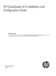
3.
Click Install/Restore License Key.
Figure 2 Install/Restore License Key screen of the Launch AutoPass window
.
4.
In the File path field, enter the path name of the license key file. Alternatively, click Browse to
search for the file.
5.
Click View file contents. The properties of the license key file appear in the License Contents
table.
6.
In the Select column of the License Contents table, select the check box of the license you want
to install.
7.
Click Install. The license is now installed.
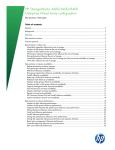
Viewing licensed capacity
From within the VSM client, in the menu bar, click Tools > License. The License dialog box appears.
Figure 3 License dialog box
.
18
HP EVA Cluster overview
The following table describes the capacities listed in the License dialog box. Each capacity features
its total amount, the amount used, and the amount available.
Table 2 License capacities
Property
Description
Basic capacity
The amount of licensed capacity allotted for basic operations (for example, the
maximum size of all pools). See Table 1 on page 17.
BC capacity
The amount of licensed capacity allotted for local replication (for example, the
size of all parents). If your license does not allow Business Copy operations, this
amount is zero (see Table 1 on page 17).
TP capacity
The amount of licensed capacity allotted for thin provisioning. If your license does
not allow thin provisioning operations, this amount is zero (see Table
1 on page 17).
CA capacity
The amount of licensed capacity allotted for remote replication. If your license
does not allow Continuous Access operations, this amount is zero (see Table
1 on page 17).
Enterprise Virtual Array Cluster Administrator Guide
19
20
HP EVA Cluster overview
2 Adding servers to the HP EVA Cluster
The EVA Cluster begins with a starter kit of cluster components, virtualization software (Volume
Manager, Business Copy, Continuous Access and Thin Provisioning), two EVAs (either EVA6400s or
EVA8400s), a pair of Fibre Channel switches, an Ethernet switch, and management servers. The EVA
Cluster is designed to be factory configured and tested so that the EVA Cluster can be easily installed
into an existing SAN.
The EVA Cluster can easily be expanded beyond two EVAs with the addition of more EVAs or other
arrays that can be added to the EVA Cluster in the field. The EVA Cluster Starter Kit and total solution
is configured to allow easy expansion with up to six arrays.
Zoning
Hosts and storage can be zoned to different DPM “quads” to distribute the load between available
DPM ports. To simplify the validation of the configuration, it is desirable to have the same hosts or
storage zoned to the same quad on each DPM. For example, hosts A and B could be zoned to quad
1 of both DPMs and hosts C and D zoned to quad 2 of both DPMs. This is called a symmetrical
configuration.
Adding new servers
This section describes special requirements when installing or upgrading host servers. When setting
up a new server, be sure to balance the workload on the DPMs by using the primary/secondary
properties of the virtual disk
Upgrading the AIX operating system
The following are two ways to upgrade the AIX operating system technology level (TL). Some of the
commands below use hdisk3 as the name of a disk, which may be different on your system.
AIX on local drive or booting from a SAN other than with the HP SVSP
NOTE:
Back up all data before attempting these upgrades.
1.
Before upgrading to a new TL/ML, remove SVSP disks. For example, use rmdev –dRl hdisk3.
To identify an SVSP disk, check the properties of the disk and look for “node_name” property
which should show the WWN of the SVSP array. For example:
# lsattr -El hdisk3|grep node_name
node_name
0x50011fe12a56ac00
2.
FC Node Name
False
Make sure that the host does not see the SVSP volumes (separate the host in the SVSP zoning).
Enterprise Virtual Array Cluster Administrator Guide
21
3.
Uninstall SVSP MPIO from the system. For example:
# installp –u devices.fcp.disk.HP.svsp.mpio.rte
Verify that it has been uninstalled properly. For example:
# lslpp -l devices.fcp.disk.HP.svsp.mpio.rte
The above command should return no output.
4.
Install the TL/ML (follow instructions provided by IBM).
5.
Reboot the server.
6.
Install the HP SVSP MPIO kit. For installation instruction, refer to the AIX SVSP MPIO installation
instructions.
7.
Bring the host back into the SVSP zone so that it can see the SVSP array.
8.
Run the cfgmgr command on the host to recognize the disks.
AIX booting from the HP SVSP (boot from SAN)
1.
Before upgrading to the new TL/ML, remove all redundant paths and keep only one path to the
SVSP disks. To identify the paths of the disk, execute following command:
# lspath –l hdisk3
NOTE:
You may have to change the host's SVSP zoning.
2.
Remove all SVSP disks except the boot disk. For example:
rmdev –dRl hdisk3
To identify the SVSP disk, check the properties of the disk and look for the “node_name” property
which should show the WWN of the SVSP array. For example:
# lsattr -El hdisk3|grep node_name
node_name
0x50011fe12a56ac00
FC Node Name
False
To identify the boot disk, execute the following command:
#bootlist –m normal -o
3.
Install the TL/ML (follow instructions provided by IBM).
4.
Reboot the server.
5.
If other SVSP disks (non-boot LUNs) were discovered again, remove the disks using the rmdev
command (see step 2).
22
Adding servers to the HP EVA Cluster
6.
Uninstall the SVSP MPIO from the system. For example:
# installp –u devices.fcp.disk.HP.svsp.mpio.rte
Verify that it has been uninstalled properly. For example:
# lslpp -l devices.fcp.disk.HP.svsp.mpio.rt
The above command should return no output.
NOTE:
Do not reboot the server.
7.
Install the HP SVSP MPIO kit. For installation instruction, refer to the AIX SVSP MPIO installation
instructions.
8.
Reboot the server.
9.
Bring in all the paths and run the cfgmgr command.
10. Check all the paths to each disk using the lspath command. For example: lspath –l hdisk3
VMware ESX Server
See Appendix C on page 157 for information on deploying a VMware ESX server with SVSP.
Aligning file system partitions for Windows (pre-2008)
1.
Windows Server 2008 does not have this problem, but for earlier versions of Windows, the
default partition set does not align the partition to the physical disk on which the partition resides.
Correct partition alignment helps reduce latency when the partition is written to, because it
eliminates the unnecessary disk writes and reads that occur when partitions are not aligned.
Windows partitions should be aligned at 64K for best results.
Enterprise Virtual Array Cluster Administrator Guide
23
2.
Partition alignment:
• Align partition with diskpart.exe for Windows 2000 or 2003, non SP1:
a.
b.
c.
d.
e.
f.
g.
Download diskpart.exe from the Windows 2000 kit and place the executable file
in the Windows system path.
Click Disk Management, and in the lower right hand side pane, note the disk number of
drive to be partitioned.
Open a command prompt and type diskpart –s for disk number.
Answer y to both questions for yes.
Enter 128 for starting offset (128 = 64K).
Insert desired partition size in MB.
Assign drive letter to partition and format it using Disk Management.
• Align partition with diskpart for Windows 2003 SP1 & R2:
a. Diskpart.exe is available on Windows 2003, however only the diskpart in Windows
2003 SP1 and higher can align disks.
b. Open command prompt and type diskpart.exe.
c. Press Enter and type list disk.
d. Note the disk number on which you want to create a partition.
e. Press Enter and type select disk 1 (or other disk number).
f. Press Enter and type create partition primary align =64.
g. At the new prompt, type assign letter z (or other letter drive) or type assign mount
C:\Folder1 (or other path of empty directory to mount the drive).
h. Press Enter and type exit to leave diskpart.
i. Format the new drive using Disk Manager.
3.
This section describes how to configure Windows Server 2003 disk partitions to be aligned
optimally for HP storage. The Windows Server 2003 default partition set does not align the
partition to the physical disk on which the partition resides. Correct partition alignment helps
reduce latency when the partition is written to, because it eliminates the unnecessary disk writes
and reads that occur when partitions are not aligned. Windows partitions should be aligned at
64K for best results.
4.
With a physical disk that maintains 64 sectors per track, Microsoft Windows always creates the
partition starting at the 64th sector—which misaligns it with the underlying physical disk. To be
certain of disk alignment, use diskpart.exe, a disk partition tool. Provided by Microsoft in
the Windows Server 2003 Service Pack 1 support tools, diskpart.exe can explicitly set the
starting offset in the master boot record (MBR). Setting the starting offset correctly will align
Microsoft Exchange I/O with storage track boundaries and improve disk performance. Microsoft
Exchange Server 2007 writes data in multiples of 8 KB I/O operations, and I/O operation to a
database can be from 8 KB to 1 MB. Therefore, make sure that the starting offset is a multiple
of 8 KB. Failure to do so may cause a single I/O operation to span two tracks, causing
performance degradation.
NOTE:
This can only be done when creating a new partition before formatting. It is not possible to
align a partition that has data on it already without losing that data.
24
Adding servers to the HP EVA Cluster
5.
Align a partition with diskpart for Windows Server 2003.
a.
Open a command prompt, type diskpart.exe, and press Enter.
b.
Type list disk. Note the disk number on which you want to create a partition.
c.
Type select disk (disk number).
d.
Type create partition primary align=64.
e.
Type assign letter (the drive letter). Or type assign mount (the path of a empty directory to
mount the drive).
f.
Type exit to exit diskpart.
Installing multipath applications
An active-passive multipath driver is required on any server that has access to the HP StorageWorks
SAN Virtualization Services Platform. Multipath information for Linux and Windows is available at
http://h18006.www1.hp.com/products/sanworks/multipathoptions/index.html. HP-UX 11iv2 requires
a purchase of the appropriate number of Secure Path licenses. (HP-UX 11iv3 does not require the
addition of a new multipath driver.) You should upgrade to the latest multipath drivers on all systems
in the SAN as soon as possible, so as not to have different versions of multipath running on various
servers.
AIX multipathing
Installing AIX multipathing
If any third-party multipath solutions, such as Antemeta or Veritas are installed, they need to be
uninstalled before installing MPIO for SVSP.
1.
Go to http://h20000.www2.hp.com/bizsupport/TechSupport/SoftwareIndex.jsp?lang=en&
cc=us&prodNameId=421504&prodTypeId=18964&prodSeriesId=421503&swLang=13&
taskId=135&swEnvOID=1043.
2.
Under Software - Storage, click Download for your version.
3.
Read and print the readme file included with the downloaded driver. The file contains installation
instructions and any limitations.
Installing AIX from the command line:
1.
# mkdir /tmp/hpmpio # or any working directory
2.
# cp devices.fcp.disk.HP.svsp.mpio.rte.1.0.0.1.aix.5.2.bff.gz /tmp/
hpmpio # from CD
3.
# cd /tmp/hpmpio
4.
# gunzip devices.fcp.disk.HP.svsp.mpio.rte.1.0.0.1.aix.5.2.bff.gz
5.
# install –acd `pwd`/
devices.fcp.disk.HP.svsp.mpio.rte.1.0.0.1.aix.5.2.bff all
To install by SMIT:
1.
# mkdir /tmp/hpmpio # or any working directory
2.
# cp devices.fcp.disk.HP.svsp.mpio.rte.1.0.0.1.aix.5.2.bff.gz # from CD
Enterprise Virtual Array Cluster Administrator Guide
25
3.
# cd /tmp/hpmpio
4.
# gunzip devices.fcp.disk.HP.svsp.mpio.rte.1.0.0.1.aix.5.2.bff.gz
5.
# smitty install_latest
COMMAND STATUS
Command: OK stdout: yes stderr: no
Before command completion, additional instructions may appear below
[TOP]geninstall -I "a -cgNQqwX -J" -Z -d . -f File 2>&1
File: devices.fcp.disk.HP.hsv.mpio.rte 1.0.2.0I:devices.fcp.disk.HP.hsv.mpio.rte 1.0.1.0
HP-UX multipathing
HP-UX 11iv2
NOTE:
Secure Path requires a right-to-use license per server.
Secure Path for HP-UX 11iv2 is no longer available, therefore support is only available to existing
users that have Secure Path.
HP-UX 11iv3
Use native multipathing.
Linux multipathing
NOTE:
Only the QLogic multipathing driver is supported at this time.
1.
Go to http://h18006.www1.hp.com/products/sanworks/softwaredrivers/multipathoptions/
linux.html.
2.
Select the QLogic driver.
3.
Select the RedHat or SUSE Linux operating system.
4.
Click Download for that product. Optionally, you can select the correct product description to
verify you made the correct selection, and download from that page.
5.
Read and print the readme file included with the downloaded driver. The file contains installation
instructions and any limitations.
After installing the multipath drivers, it is a good idea to verify the paths between the server and the
DPM. Enter the following command:
[prompt]# hp_rescan –a
In response, you should see a path through both ports to every attached device.
If you encounter an issue with the Linux device paths changing between server power cycles because
the persistent binding is not configured correctly, use the following procedure:
26
Adding servers to the HP EVA Cluster
1.
Install the failover QLogic multipath driver.
2.
Before mapping any LUNs to the host, open the SANsurfer GUI and choose the first port.
3.
Select the persistent binding tab and select the check box under "Bind All" and choose a target
ID for each of the targets mapped and select Save.
4.
Perform a similar binding on the other HBA port.
5.
Map the LUNs from the VSM to this host and scan for the virtual disks at the host using the
hp_rescan -a utility.
6.
Refresh the SANsurfer GUI and change the target ID of one target (for example, change it to 3).
Observe that the rest of the targets are grayed out.
7.
Create a new initrd image using mkinitrd <initrd image path> <kernel_version>.
8.
Edit the file /boot/grub/menu.lst to boot with the new initrd image and reboot. During the
reboot, observe that the new target ID is used for all the LUNs. This can be verified when we
display all the LUNs using lssd. On subsequent reboots the device IDs should not change.
OpenVMS multipathing
Multipathing is integrated with the operating system.
Solaris 9 multipathing
This procedure configures a Solaris 9 server for use with SVSP:
1.
2.
Enable MPxIO:
a.
Install the StorEdge Foundation Suite (use the install_it script).
b.
Edit the /kernel/drv/scsi_vhci.conf file and change mpxio-disable=”yes” to
mpxio-disable=”no”.
Disable AutoFailback:
a.
Open the /kernel/drv/scsi_vhci.conf file in a text editor.
b.
Disable the automatic failback capability by changing the auto-failback entry to:
auto-failback="disable";
c.
Save and exit the file.
d.
Perform a reconfiguration reboot:
# touch /reconfigure
# shutdown -g0 -y -i6
3.
Verify the system is working:
# cfgadm –al
# devfsadm –Cv
# format (to see all the volumes mapped)
4.
Make sure you are using the correct HBA driver.
Solaris 10 multipathing
This procedure configures a Solaris 10 server for use with SVSP:
Enterprise Virtual Array Cluster Administrator Guide
27
1.
2.
Enable MPxIO:
a.
The MPxIO driver is installed and disabled by default on Solaris 10 SPARC servers for Fibre
Channel devices. To enable MPxIO, type # stmsboot –e. A reboot is required.
b.
The MPxIO driver is installed and enabled by default in Solaris 10 x86–based servers. To
verify, open /kernel/drv/fp.conf and check for the line: mpxio-disable=”no”;.
Ensure it is set to “no” (MPxIO enabled).
Disable AutoFailback:
a.
Open the /kernel/drv/scsi_vhci.conf file in a text editor.
b.
Disable the automatic failback capability by changing the auto-failback entry to:
auto-failback="disable";
c.
Save and exit the file.
d.
Perform a reconfiguration reboot:
# touch /reconfigure
# shutdown -g0 -y -i6
3.
Verify the system is working:
# cfgadm –al
# devfsadm –Cv
# format (to see all the volumes mapped)
4.
Make sure you are using the correct HBA driver.
VMware multipathing
For VMware, the multipathing policy must be set to the Most Recently Used (MRU) path.
Windows multipathing
1.
Go to http://h18006.www1.hp.com/products/sanworks/softwaredrivers/multipathoptions/
windows.html.
2.
Under Select your product, click Windows MPIO DSM for SVSP. This product contains an
active-passive multipath driver.
3.
Select your operating system.
4.
Select your software/driver language.
5.
Select HP MPIO Full Featured DSM, and then click Download for that product version.
6.
Read and print the readme file included with the downloaded driver. The file contains installation
instructions and any limitations.
7.
Disconnect the server from the SAN.
8.
Install the multipathing drivers.
In a configuration with a large number of devices grouped with a large number of paths, there can
be a long boot up time as Windows detects devices and loads drivers. After the drivers are installed,
you must enable persistent binding to maintain consistent driver letters. Described below are procedures
for QLogic and Emulex HBAs.
28
Adding servers to the HP EVA Cluster
QLogic HBAs with Windows
To enable persistent binding with QLogic HBAs:
1.
Launch Sansurfer. This application can be downloaded from hp.com or qlogic.com.
2.
Connect to Localhost. The utility displays all QLogic HBAs recognized in the system.
3.
Select the port on the HBA to be enabled for persistent binding.
4.
Select the Target Persistent Binding tab.
5.
Bind the WWPN to a Target ID.
6.
Click Save, and enter the password on the security check popup. If this is the first time you have
used the SanSurfer application, and you have not changed the default password, the password
is config.
7.
Restart the server to make the changes effective.
The HBA saves this information. It makes no difference in what order the arrays are scanned. The
HBA assigns the saved target ID to the WWPN.
Emulex HBAs with Windows
To enable persistent binding with Emulex HBAs:
1.
Launch the HBAnyware utility. This application can be downloaded from hp.com or emulex.com.
2.
Select a port on an HBA from the list displayed on the left side of the screen.
3.
Select the Target Mapping tab.
Enterprise Virtual Array Cluster Administrator Guide
29
4.
Bind to the WWPN by clicking on a Target WWPN, and then clicking the Add Binding button.
Either accept the default entries or change them as appropriate and click OK.
5.
Restart the server activate the changes.
Presenting SVSP virtual disks to servers
The HBAs of a server need to be defined so that the DPM can customize its interface to the operating
system of the server that will be using the virtual disk. This is done by creating a user defined host
(UDH), which is an alias definition for the server's HBAs with a common property that sets the operating
system. The DPMs use the UDH for selective LUN presentation to one or more UDHs. If the UDH is
not defined, a virtual disk can be created, but cannot be presented to a host. To be used, a UDH
must be created. Granting access permissions is done per UDH, and not per HBA.
NOTE:
Verify that the appropriate multipath drivers are installed and configured before presenting (or
re-presenting in the case of a replacement server) any LUNs from the SVSP domain to the server.
Creating the user defined host (UDH)
NOTE:
Knowing the WWPN or WWNN of the server HBAs is helpful before starting this procedure. This
information can usually be found using the server's device management tools or a query to the Fibre
Channel switch to which the server is attached (for example, display the switch's name server entries).
1.
Place a mouse cursor on the host menu.
2.
Right-click and select New.
3.
Follow the wizard prompts that ask for a host name, OS type, and LUN range.
Creating VSM virtual disks
1.
30
Place a mouse cursor over the virtual disk identity in the left-side menu.
Adding servers to the HP EVA Cluster
2.
Right-click and select New.
3.
Follow the prompts.
4.
Present to a previously defined UDH.
5.
On the server (UDH), discover the new LUN.
Defining hosts in SVSP
This section describes how to attach SVSP virtual disks to servers by operating system.
AIX servers
Not available at the time of publication.
HP-UX servers
1. Run ioscan on all HP-UX hosts.
2.
Create HP-UX user-defined hosts (UDHs) from absent HBAs.
3.
Right-click on HP-UX UDHs and set the host to offline.
4.
Present volumes to the offline HP-UX hosts.
5.
Run ioscan on all HP-UX hosts.
6.
Right-click on HP-UX UDHs and set the hosts to online.
Linux servers
It may be necessary to reboot the Linux server to allow the discovery of HBAs by the VSM application.
OpenVMS servers
Not available at the time of publication.
Solaris servers
Not available at the time of publication.
VMware servers
To discover a new SVSP virtual disk:
1.
Launch the Virtual Infrastructure client.
2.
Select the ESX server to which you have presented a new virtual disk.
3.
Select the Configuration tab.
4.
On the left side, under Hardware, select Storage Adapters.
5.
Near the top, right window, click Rescan.
6.
In the Rescan dialog box, select the Scan for Storage Devices and Scan for New VMFS Volumes
checkboxes and click OK. The bottom half of the window displays new LUN information that
includes the path.
Enterprise Virtual Array Cluster Administrator Guide
31
7.
Follow the VMware instructions to create a DATASTORE and to make the newly discovered virtual
disk visible to a guest operating system.
Windows servers
Use Disk Manager to discover and initialize the new devices.
32
Adding servers to the HP EVA Cluster
3 Zoning
Zoning is a critical part of the configuration process for HP SVSP since it can directly impact the
capacity, stability, and performance of the overall system. Failure to implement a correct zoning
configuration can lead to a nonfunctioning configuration or one that operates in a reduced state with
respect to capacity, performance, and high availability.
Zoning overview
Any given device port on the SAN can communicate with every other device port when zoning is
disabled. Zoning provides a standard access control mechanism for fabrics. When a zoning
configuration is implemented, a device port can only see the other device ports with which it shares
a zone. Administrators should refer to the manuals of their switch manufacturers. The following sections
describe in detail what zones need to be created, but does not go into detail on how this is
accomplished.
There are two types of zoning enforcement mechanisms:
• Soft zoning. A node is assigned to a zone according to its Fibre Channel World Wide Name
(WWN), and the switch places designated WWNs in a zone without regard to which ports they
are connected.
• A name server restricts visibility
• Always available with zoning is enabled
• No reduction in performance
• Hard zoning. A device is assigned to a zone by reference to a port. Anything connected to the
port is then in that zone.
• Available when certain rule checking criteria are met through hardware logic checking
• Provides additional security over soft zoning
• Prevents illegal access from unwanted sources
• No reduction in performance with hard-port level zoning
Soft zoning is easier to manage in an environment where the configuration is constantly changing.
HP recommends that you use soft zoning for HP SVSP zoning configurations, although an administrator
may choose hardware zoning if it is more familiar.
The key point to remember when zoning is that all devices in the same zone will be able to see one
another on the SAN. Limiting these types of unwanted interactions between devices is the basis of
the general guidelines for zoning in a given SAN.
When implementing an HP SVSP zoning configuration, the following practices can help make the
process as straightforward as possible and minimize errors:
• Draw a diagram of the zoning configuration prior to implementing the zoning. Having a visual
representation of the configuration helps to identify interactions between different devices in the
SAN and can later be useful in debugging any issues, such as performance bottlenecks or unwanted
access to a certain device.
Enterprise Virtual Array Cluster Administrator Guide
33
• Use zoning objects, often called aliases, on the switch as zone members. Zoning objects allow
you to create logical representations on the switch of physical devices and ports in the SAN. These
objects can be modified or removed as the physical topology changes and are easier to manage.
• Follow a logical naming convention for zoning objects and zones that is readable and can be
understood by anyone with knowledge of the HP SVSP. For example, a zoning object name (for
example, VSM1_H1_5a14) could tell someone the device, the HBA on the device, and what port
number on the device, that the object represents. Similarly, a zone name could tell someone which
zoning objects are contained in the zone. Naming conventions are a personal preference but
should convey meaningful information about the zone and be easily understood. Tables 1 and 2
in the Zoning Components in HP SVSP section provide an example naming convention that can
be used with HP SVSP.
• Verify the zoning configuration afterwards. Devices being able to see each other and accessing
presented virtual disks or LUNs is no guarantee that the zoning configuration is correct with all
the expected paths between devices. Some zoning errors will not manifest themselves until certain
events, such as a path failover, occur. Using path failover tests within a fabric and across fabrics
should be a part of zone verification for HP SVSP.
• Use symmetric zoning rules and standard naming conventions in both fabrics.
HP SVSP zoning principles
An HP SVSP zoning configuration is different from zoning implemented in other SANs that have
devices that are strictly categorized as target or initiator devices. In HP SVSP, the VSM and Data Path
Module (DPM) are unique devices that act as both targets and initiators. Devices within an HP SVSP
configuration can be divided into five distinct types:
1.
2.
3.
4.
5.
DPM—The backbone of HP SVSP that acts as a hardware virtualization device between hosts
and storage devices connected to it.
VSM—HP SVSP management servers that perform a function similar to HP Command View. The
VSM also has the additional function of implementing HP SVSP data mover functions such as
import, migration and replication.
Storage—Back-end storage devices that provide the underlying storage being virtualized and
managed by HP SVSP.
Host—Front-end devices, which access the virtualized storage through HP SVSP.
Management—Devices that access the back-end storage devices directly for the sole purpose of
configuring them for use with HP SVSP.
An HP SVSP zoning configuration can logically be divided into front-end and back-end zones
depending on the interaction between the devices in the zone. The general rule is that any zone used
to access an HP SVSP virtual disk is a front-end zone while any zone containing a storage device or
dealing with the underlying storage I/O is a back-end zone. This distinction between front-end and
back-end zones is particularly important if it is necessary to install additional front-end and back-end
switches to support additional devices. All HP SVSP zones should follow these basic guidelines to
ensure the most stable, manageable configuration possible:
• Each zone contains a target device and an initiator device. In the case of the DPM and VSM,
these devices can be classified as targets or initiators, depending on what device they are interacting with in a given zone. For example, in a Host-DPM zone, the DPM is the target while the
host is the initiator. However in a DPM-Storage zone, the DPM is the initiator while the storage
device is the target.
• Each zone contains exactly two device types. For example, HP recommends you have different
zones for the DPM-VSM and Storage-DPM rather than having a single zone containing the DPM,
VSM, and storage devices.
34
Zoning
NOTE:
Since a VSM port can act as either a target or initiator, having ports from the same VSM in a
single zone can lead to unpredictable behavior and should be avoided. HP recommends all
VSM-related zones have at most one port from each VSM.
• Each zone contains a single initiator device but may contain multiple target devices. A target
device can be represented by multiple ports but an initiator device is represented by only a single
port. Multiple target devices may be placed in a single zone when it can be verified that they are
strict target ports. For example, multiple ports from different EVAs may occupy a single back-end
storage related zone. However, VSM ports which have both target and initiator behavior should
only be regulated to a single port in any given zone.
• Interaction between different zones must be taken into account if they share any devices. For example, if two different hosts are accessing the same DPM front-end port through separate zones,
it is important to consider the possibility that the port might become a bottleneck in the configuration
if both hosts are accessing it simultaneously.
Following these guidelines when implementing an HP SVSP zoning configuration allows for simple,
easy-to-understand zones that provide a high degree of control over the activity and allocation of
resources in the SAN. Some exceptions to these general guidelines can be made but only in the case
when the properties of all devices in the zone are well-defined and fully understood. Devices can be
added or removed from the SAN by adding or removing the respective zones to which they are a
member from the active configuration without reconfiguring zones and potentially impacting other
devices. Using “super zones” with a large number of devices is highly discouraged with HP SVSP,
since this can lead to unpredictable communication between devices over the SAN and makes the
zone configuration harder to adjust in the future.
Zoning components in HP SVSP
This section describes zoning between specific components in HP SVSP. Given the complex nature
of the HP SVSP with multiple devices and interactions, the overall zoning configuration can be difficult
to understand if presented in its entirety. By examining each type of zone and providing general
zoning templates, the material in this section can be applied to a wide range of configurations with
different devices. The following zone types will be examined in detail in this section:
•
•
•
•
•
DPM-Host zone
DPM-Storage zone
DPM-VSM zone
VSM-Storage zone
VSM-VSM zone
Figure 4 illustrates a high-level view of the interaction between devices displaying the types of zones.
Each two-way arrow represents a zone type. Table 3 shows an example of zone naming conventions
for each HP SVSP zone type. Table 4 shows an example of an alias naming convention for each HP
SVSP device port type.
Enterprise Virtual Array Cluster Administrator Guide
35
Figure 4 Five zone types
.
Table 3 Example naming convention for zone types
Zone type
Naming template
Example
DPM-Host
<Host Name>_<last 4 digits of host port
WWN>_<DPM1 Name>_<last 4 digits of DPM port
WWN>_<DPM2 Name>_< last 4 digits of DPM port
WWN>
HOSTA_5a46_DPM1_0320_
DPM2_0340
DPM-Storage
<DPM Name>_<last 4 digits of DPM port WWN>
<ArrayName>_<CtrlA>Port#>_<CtrlB><Port#>…
<CtrlN><Port#>
DPM1_0321_EVA1_
CTRLA1_CTRLB1
DPM-VSM
<DPM Name>_<last 4 digits of DPM port WWN>_
<VSM name>
DPM1_0321_VSM1
VSM-Storage
<VSM Name>_<last 4 digits of VSM port WWN>_
<Array Name>
VSM1_5a14_EVA1
VSM-VSM
<VSM1 name>_<VSM2 name>
VSM1_VSM2
Table 4 Example naming convention for device port types
Port Type
Naming Template
Example
DPM port
<DPM Name>_<last 4 digits of DPM port WWN>
DPM1_0321
VSM port
<VSM port VSM Name>_<last 4 digits of VSM port
WWN>
VSM1_5a12
Storage port
<Array Name>_<Ctrl Name><Port #>
EVA1_CTRLA2
Host port
<Host Name>_<last 4 digits of host port WWN>
HOST1_5c32
36
Zoning
NOTE:
• The zoning templates shown in this section refer to a single domain with DPM pair configurations
that have two or four licensed quads on the DPM. The rules and guidelines described in this section
can be applied to other configurations with multiple domains or DPM pairs with a different number
of licensed quads.
• All examples involving storage related zones in this section will use the HP EVA and HP Command
View EVA. The rules and guidelines described in this section can be applied to configurations
containing other types of multi-controller storage arrays. Zoning for the management station to
the storage device is not discussed.
Dual-fabric device configuration
HP SVSP must be deployed over a dual-fabric SAN configuration. Switches in each network are
required to be from a single vendor, although each fabric can have switches from a different vendor.
As much as possible, the fabrics should be mirror images of each other. In this section the dual-fabric
layout is referred to as the blue-fabric and the red-fabric. From a connectivity point of view, each
zone in the blue-fabric (blue zone) should have a corresponding zone in the red-fabric (red zone) that
contains the same target and initiator devices as well as number of ports for each device. At the
sub-device level, the ports of each component in the device should also be split evenly over the
mirroring fabrics. For example, a host with a single dual-port HBA should have one port mapped to
a red zone and the other port mapped to a blue zone. Similarly, in a dual-controller storage device
with two ports per controller (for example, the HP EVA4400), each controller should have a port
mapped to a red zone and the other mapped to a blue zone. Each device deployed within an HP
SVSP configuration must have at least two physical ports to provide the capability to split the device
symmetrically over the dual-fabric. Figure 5, Figure 6, Figure 7, and Figure 8 show the dual-fabric
device configuration for each HP SVSP device type.
Figure 5 Dual-fabric port configuration for 4–port and 8–port dual-controller back-end storage devices
.
Figure 6 DPM dual-fabric port configuration
.
Notice how each DPM quad has a target and initiator on both the red and blue fabrics.
Enterprise Virtual Array Cluster Administrator Guide
37
Figure 7 Single VSM dual-port configuration
.
Figure 8 Host server dual-port configuration
.
DPM-host zoning
A DPM-Host front-end zone is used to give a host access to the virtual disks created in HP SVSP and
presented through the DPM front-end target ports. A front-end path between the DPM and the host
consists of a single host port and a single DPM front-end port. The following rules must be applied
when creating DPM-Host zones:
• Each host port on a single host is zoned to exactly one front-end target port from each DPM.
Zoning to a port from each DPM allows for failover capabilities if the active DPM fails or the
particular active front-end port fails. Having front-end ports from multiple DPMs is allowed since
each DPM front-end port is strictly a target port in HP SVSP and has no interaction with other DPM
ports.
• Each host port on a single host is zoned to a different port on a given DPM. Zoning multiple ports
on a host to a single DPM front-end port leaves the configuration vulnerable to a loss of availability
if the DPM port fails.
Using the rules described, each zoned host port has exactly two front-end paths to a presented virtual
disk with one front-end path through each DPM.
If the DPM pair is in an active/passive relationship (a relationship used in all HP SVSP releases up
to and including v3.0), only the paths through the active DPM for a virtual disk are used at any given
time while passive paths are used only in failover scenarios. The number of front-end paths that a host
can have through a single DPM is directly dependent on the number of host ports in the configuration
that are zoned to that DPM.
Since the DPM is a shared resource with finite capacity, it can only handle a finite number of front-end
paths (see the product release notes for the maximum number of paths and volumes supported by HP
SVSP). For example, a configuration with only a single host can allow the host to have the maximum
number of front-end paths to the DPM (one path to each DPM front-end port). If there are a large
number of hosts connected to the DPM then having the maximum number of front-end paths for each
host is not always the best configuration since it can lead to reduced performance due to the increased
contention for shared resources. The following recommendations are made to balance capacity and
performance in the overall configuration:
• Each host port has at most two front-end paths to each DPM along each fabric. This is a recommended limit of eight front-end paths for each host with four front-end paths through each DPM.
• Limit the number of DPM target ports in each DPM-Host zone to one quad on a single DPM.
38
Zoning
• Use one operating system in each individual DPM-Host zone. This can be done by implementing
only single initiator port zones as previously discussed in the zoning guidelines.
Figure 9 illustrates zoning between a single server with two dual-port HBAs and the first two quads
of a DPM pair with the recommended limit of eight front-end paths. Paths between server initiator
ports and DPM front-end target ports are color coordinated to represent the different zones to which
they belong within the red and blue fabrics.
Figure 9 Zoning from server to two quads of a DPM pair
.
It is common for multiple hosts to be zoned to the same DPM front-end target ports, particularly in
larger configurations where the number of host ports outnumber the DPM ports.
Figure 10 illustrates zoning between two servers with single dual-port HBAs and the first two quads
of a DPM pair with the servers being isolated from each other by being zoned to different quads on
each DPM.
Figure 10 Zoning between two servers and two quads of a DPM pair
.
Figure 11 illustrates zoning between two servers with two dual-port HBAs and the first two quads of
a DPM pair with the servers being zoned to the same DPM front-end target ports.
Enterprise Virtual Array Cluster Administrator Guide
39
Figure 11 Zoning between two servers with two HBAs and two quads of a DPM pair
.
DPM-storage zoning
A DPM-Storage back-end zone is used to give the DPM access to the back-end storage used to create
virtual disks managed by HP SVSP. A back-end path between the DPM and back-end storage consists
of a single DPM back-end initiator port and a single port on a back-end storage device controller.
The following rules must be applied when creating DPM-Storage zones:
• Each DPM back-end initiator port is zoned to exactly one port from each controller on a back-end
storage device. This allows for back-end failover capabilities if a storage device port or the controller fails.
• Each DPM back-end initiator port is zoned to a different port on a given back-end storage device
controller. Zoning multiple DPM ports to a single storage device port leaves the configuration
vulnerable to a loss of availability if the storage port fails.
• Each storage device port is zoned to exactly one back-end initiator port from each DPM. Zoning
to a port from each DPM allows for back-end failover capabilities if the active DPM fails or the
particular active back-end port fails.
• Each zone has a maximum of four storage device ports. (This rule is necessary when zoning larger
arrays with more storage device ports and controllers such as the XP array.)
Using these rules, each zoned DPM back-end initiator port has exactly one back-end path to each
controller in a storage device. In the case of the HP EVA being the storage device, the dual-controller
configuration translates into two paths to the EVA through each DPM back-end initiator port. The
number of overall back-end paths is dependent on the number of ports on the storage device. For
example, an HP EVA4400 has two ports on each controller, which would equal four back-end paths
through each DPM, while the HP EVA8100 has four ports on each controller that would equal eight
paths through each DPM.
Figure 12 illustrates full zoning between a dual, dual-port controller back-end storage device and the
first quad of each DPM. Paths between DPM initiator ports and storage device target ports are color
coordinated to represent the different zones to which they belong within the red and blue fabrics.
40
Zoning
Figure 12 Zoning between 2 dual-port controllers and first quad of each DPM
.
Figure 13 illustrates full zoning between a dual, quad-port controller back-end storage device and
the first two quads of each DPM.
Figure 13 Zoning between 2 quad-port controllers and two quads of each DPM
.
If greater control over the available paths to each LUN is required (for example, to improve load
balancing), use a combination of more restrictive zoning and LUN presentation to the DPM from the
back-end storage device.
Unlike the DPM-Host zoning where the front-end paths created to a DPM are considered similar to
one another, the paths in the DPM-Storage zoning are very different from one another. Depending
on the type of back-end storage device and its firmware, there are generally two types of back-end
path relationships: active/passive paths or active optimized/non-optimized paths. With active/passive
back-end paths, the LUN can only be accessed through the active paths. This behavior is similar to
the active/passive relationship between DPMs and hosts in an HP SVSP domain. Active
optimized/non-optimized paths allow for the LUN to be accessed through either type of path. As the
name suggests, accessing a LUN using the non-optimized path can lead to less than the peak
performance expected from the storage device. This is true in the case of the HP EVA where using
Enterprise Virtual Array Cluster Administrator Guide
41
the active non-optimized paths for reads to a LUN results in internal proxy I/Os between storage
controllers and should be avoided.
The DPM has a back-end multipath driver with properties similar to a basic multipath driver. A path
table is constructed with all back-end paths available for each LUN. The status of each path and
whether the path is active/active optimized or passive/active non-optimized is based on information
provided by the back-end storage device. There is no active load balancing and back-end paths to
each LUN are chosen at initialization time using a round robin approach between available
active/active optimized paths, so all paths are used equally. This approach does not take into account
the actual load placed on the LUNs during runtime. Changing paths to a LUN only occurs in the event
that the current back-end path being used is no longer available. Passive and active non-optimized
back-end paths are only used in the event that no active/active optimized back-end paths to a LUN
are available.
While the DPM back-end multipath driver is capable of detecting path types and doing simple static
load balancing, the limitations of the driver and how it can affect zoning should be considered. The
key limitation is that there is currently no mechanism in the DPM to control the back-end multipath
choices and the DPM makes these choices arbitrarily without regard for the I/O access patterns to
each LUN. By treating all LUNs equally in the round robin scheme, this may result in some cases
where the actual I/O load balance over the DPM back-end ports is inefficient. For example, if there
are 2 available active optimized paths to a back-end storage device with 4 LUNs presented to the
DPM, the DPM would access 2 LUNs along each active path. This approach would be sufficient unless
there are 2 LUNs that expect a large amount of I/O while the other 2 have only a small amount of
I/O . If the 2 LUNs with more I/O are accessed along the same fixed path, this can lead to a situation
where one back-end path has reached its peak capacity while the other is underutilized.
In the case where situations such as the one described in the previous example are possible, greater
control over the available paths to each LUN may be required. This can be done by using a
combination of more restrictive zoning and LUN presentation to the DPM from the back-end storage
device. One possible approach that has been used is to zone each DPM back-end port to a storage
device port and presenting each LUN only to a specific DPM back-end port zoned to the managing
storage device controller for the LUN. This approach offers the most control over which back-end port
is used to access a given LUN but ignores any need for high availability that a customer environment
would have normally. A similar approach is to limit LUN access on a per-quad basis where LUNs
with more I/O can be separated onto different quads. The tradeoffs between performance, high
availability, and the complexity of the system should be considered if a custom zoning and presentation
configuration is implemented on the back-end.
DPM-VSM zoning
A DPM-VSM back-end zone is used to give the VSM access to the back-end initiator ports of the DPM
to manage the DPM LUN mapping information and facilitate data mover functions involving mirroring,
local snapshots, and remote replication. A back-end path between the DPM and the VSM consists of
a single DPM back-end initiator port and a single port on the VSM. In this type of zone, the VSM acts
in the target role. Each DPM back-end initiator port is zoned to all VSM ports on the given fabric.
Unlike the DPM-Host or DPM-Storage zoning, there is no limitation on the number of paths that exist
between the VSM and DPM. Each DPM-VSM zone has a single DPM back-end initiator port and a
single VSM port resulting in eight separate DPM-VSM zones for each DPM quad.
Figure 14 illustrates zoning between VSMs and the first quad of each DPM. This can be duplicated
for additional DPM quads by adding more zones. Paths between DPM initiator ports and VSM target
ports are color and shape coordinated to represent the different zones to which they belong within
the red and blue fabrics.
42
Zoning
Figure 14 Zoning between VSMs and first quad of a DPM pair
.
VSM-storage zoning
A VSM-Storage back-end zone is used to give the VSM access to the ports of the back-end storage
device to manage the storage being virtualized by SVSP, and facilitate data mover functions involving
the “soft path” such as mirroring, local snapshots, and remote replication. A back-end path between
the VSM and the storage device consists of a single port on the VSM and a storage device port. In
this type of zone, the VSM acts in the initiator role. Each VSM port is zoned to all storage device
ports on a given fabric. A VSM-Storage zone may contain a single VSM port and multiple storage
device ports. The VSM server is limited on the total number of access paths that can be exposed to
back-end LUNs. The restriction is set according to the capabilities of the OS that runs the VSM
(Windows 2008). However, there is a limitation on the number of back-end LUNs that can be presented
to the VSMs. See the product release notes for the maximum number of back-end LUNs supported by
HP SVSP. Each zone has a single VSM back-end initiator port and multiple storage device target
ports.
Figure 15 illustrates zoning between VSMs and a dual, dual-port controller back-end storage device.
This can be extended for storage devices with more ports by adding them to the existing zones. Paths
between the storage device target ports and VSM initiator ports are color coordinated to represent
the different zones to which they belong within the red and blue fabrics.
Figure 15 Zoning between VSMs and two dual-port back-end controllers
.
Enterprise Virtual Array Cluster Administrator Guide
43
VSM-VSM zoning
The VSM-VSM zone allows the VSMs in an HP SVSP configuration to communicate with each other
over the SAN in order to determine VSM connectivity state and manage failover behavior between
the VSMs. This special purpose zone is not classified as a front-end or back-end zone since it does
not involve any storage devices or hosts. In this type of zone, a VSM is not strictly classified as a
target or initiator. When creating VSM-VSM zones, each port on a VSM must be zoned to all ports
on the other VSM on the given fabric. For consistency purposes, HP recommends that each VSM-VSM
contains a single port from each VSM. Figure 16 shows the recommended zoning.
Figure 16 Zoning between two VSMs
.
44
Zoning
4 HP StorageWorks Management
Infrastructure
The HP StorageWorks Management Infrastructure is installed with the HP Command View SVSP client.
HP Command View SVSP is the GUI that supports the HP EVA Cluster. The Management Infrastructure
software provides storage-related security features and user interface capabilities. This chapter covers
the use of the following:
• Configuration interface
• Security interface
Quick tours
Configuration interface – details page quick tour
The Configuration page allows you to view and change configuration settings. The main areas of the
page are identified in the following illustration. Each of the configuration setting types, General,
Discovery, Security and Tree Integrator are displayed in expandable panels.
1. Actions
2. Service state
3. Configuration status
4. Configuration details
Enterprise Virtual Array Cluster Administrator Guide
45
Configuration interface – registry page quick tour
The Registry page allows you to view registry entries.
46
HP StorageWorks Management Infrastructure
Security interface – Management Group page quick tour
The Management Group page allow you to view key characteristics of a Management Group, change
authenticator states, and open the Move Machine wizard.
1. Management Group
2. Actions
3. Authenticating OS security domains
4. Machines and authenticator state
Security interface – Move Machine wizard quick tour
The wizard guides you through the steps to remove a member from a Management Group and add
it to another Management Group, or to create a new Management Group and add it to the new
group.
1. Management Group machine being changed to a different Management Group
Enterprise Virtual Array Cluster Administrator Guide
47
Management Infrastructure concepts
Discovery
All machines with Management Infrastructure software which are on the same LAN can automatically
discover and communicate with each other.
To do this, the Management Infrastructure discovery component on each machine stores information
about its web service API and other functions in a local Management Infrastructure registry. The local
registry information is available to all Management Infrastructure services and each discovery
component synchronizes its registry with other discovery components. Management Infrastructure
components can then look up web services from other Management Infrastructure components. The
distributed and replicated registry approach is supported on IPv4 and IPv6 networks using multicast,
broadcast, and range-scanning techniques, as appropriate.
Although discovery components can belong to only one Management Group at a time, they are aware
of, and communicate with, all discovery components that are visible on the LAN.
A Management Infrastructure discovery component is included in each instance of Management
Infrastructure software.
Discovery configuration settings include:
Registry port, page 65
Non-local registry entry time-out, page 65
Management port, page 64
Registry table updates, page 65
Discovery interval, page 64
Registry update address (IPv4/IPv6), page 65
Discovery URI, page 64
Security integration
The Management Infrastructure security function includes: authenticating users, establishing trust
between Management Infrastructure components, grouping machines into Management Groups,
handling single sign-on and auditing.
The Management Infrastructure security component creates Management Groups. A Management
Group can be local to the machine that the security component is on, or it can include other machines.
The Management Group concept is very similar to network security domains.
Management Infrastructure security components locate each other using the Management Infrastructure
discovery registry and can replicate certificates to all member machines in the Management Group.
This allows services on other machines to access security credentials for a service on another machine.
This approach allows Management Infrastructure capable applications to share a common security
model. This is possible even when the applications are on different machines, use different operating
systems, and are written in different programing languages.
A Management Infrastructure security component is included with each instance of Management
Infrastructure software.
Security configuration settings include:
Login service port, page 66
48
HP StorageWorks Management Infrastructure
Management Group communication service port, page 67
Local service port, page 66
Available OS security domains, page 66
Management Group management service port, page 67
User interface integration (SPoG and trees)
The Management Infrastructure user interface integration function allows multiple Management
Infrastructure capable user interfaces to be displayed in a single browser-based interface.
This function is implemented by various components and mechanisms, including: Management
Infrastructure single-pane-of-glass (SPoG) component, Management Infrastructure tree integrator
component, tree source, and tree decorator.
SPoG. The SPoG displays Management Infrastructure capable application interfaces in a browser
window. Application pages are displayed in the Management Infrastructure content pane and a
unified tree represents all registered applications in the Management Infrastructure navigation pane.
Before an Management Infrastructure application can display its content and tree in the SPoG, it is
registered by the discovery component. The Management Infrastructure user interface runs in a browser
and can run on multiple client machines at the same time.
Tree integrator. After applications are registered, the tree integrator aggregates the trees and makes
the unified tree available for the SPoG to display.
Tree source. The tree source mechanism manages the list of trees to be displayed by responding to
queries from the tree integrator and notifying the integrator of changes to each tree.
Tree Decorator. The tree decorator mechanism allows additional URLs from other applications to be
added to a tree node.
Tree integration configuration settings include:
Tree integrator port, page 69
Tree age time-out, page 68
SPoG port, page 68
SPoG time-out, page 68
Tree decorator port, page 68
SPoG time-out, page 68
Discover new tree interval, page 67
Applications (Management Infrastructure specific)
The term Management Infrastructure application refers to an HP storage management product or
software component that is Management Infrastructure capable, usually for the purposes of participating
in Management Infrastructure security integration and user interface integration.
Authenticators (Management Infrastructure specific)
A Management Group member machine is an authenticator if it can authenticate Management
Infrastructure users.
• Authenticator machines in the same Management Group can be members of different OS security
domains.
Enterprise Virtual Array Cluster Administrator Guide
49
Configuration settings and service startup
When Management Infrastructure software is first installed on a machine, the default settings are
applied and there is no Management Infrastructure configuration file. When you make and save the
first change using the configuration interface, Management Infrastructure software creates a
configuration file and writes the changes to the file. All subsequent configuration changes are written
to the configuration file.
If no changes are made to the configuration settings, the default settings are applied whenever the
Management Infrastructure service is started. Once any setting is changed, the settings in the
configuration file are applied whenever the Management Infrastructure service is started.
See also “Restoring the default configuration for a machine” on page 60.
Interface server (Management Infrastructure specific)
The term interface server refers to the Management Infrastructure software which runs the user interface
integration functions.
Log in user names
When logging in to an Management Infrastructure interface, HP recommends that you enter a qualified
user name. That is, enter a name that includes a valid OS security domain, for example,
user@machine, user@domain, machine/user or domain/user.
If you enter an unqualified user name (one with no explicit domain), Management Infrastructure will
silently append the local machine name. Because of the distributed nature of the Management
Infrastructure environment, this could lead to authentication issues.
OS security domains
The term OS security domain refers to a security domain which is managed by an Management Group
member machines's operating system. All OS security domains have an associated type. For example,
in Windows the types are: local and active directory.
Registry (Management Infrastructure specific)
The term registry refers to the distributed registry tables where Management Infrastructure discovery
components store information and where Management Infrastructure capable applications can advertise
their services and find the services that they need. A registry is located in every discovery component
on every Management Infrastructure server.
The distributed Management Infrastructure discovery components cooperate to replicate their registries
and to forward lookup requests, if necessary. There is no central discovery component or registry.
You can view a registry page in the configuration interface. See “Configuration interface – registry
page quick tour” on page 46.
Management Group security certificates
Each Management Group uses a unique self-signed security certificate to manage login access.
50
HP StorageWorks Management Infrastructure
When browsing to an Management Infrastructure interface, if there is no trusted certificate authority
in the Management Infrastructure environment to attest to the certificate, then connection to Management
Group member machines is blocked.
This condition can be resolved by installing the Management Group self-signed certificate in the
browser as a trusted certificate authority. See “Management Group security certificate installation
overview” on page 54.
• When an installed Management Group certificate is valid, the next time the browser connects to
the Management Group member machine, the connections will be automatically authenticated.
• When an installed Management Group certificate is not valid, then a message will appear for the
user to make a decision. If the user does not additionally accept the invalid certificate, then the
connection will fail.
For a security certificate to be considered valid by a browser, the following conditions must be met:
• The certificate can be authenticated by a trusted certificate authority.
• The dates on the certificate must be valid.
• The common name, or entry in subject alternative name section on the certificate, must match the
address the browser client is using to connect to the Management Infrastructure service.
Service (Management Infrastructure specific)
The term Management Infrastructure service refers to the Management Infrastructure process which
runs in the background on an Management Infrastructure server. The Management Infrastructure
service must be restarted to apply changes to an Management Infrastructure configuration.
IMPORTANT:
To avoid the possibility of interrupting storage related operations, HP recommends that you carefully
plan and coordinate restarting the Management Infrastructure service.
Management Groups
A Management Group is a set of Management Group machines.
Management Groups allow you to:
• Log in to any member of a Management Group, or to Management Infrastructure capable application, using a single credential (single sign-on).
• Specify the machines and OS security domains to be used as authenticators for access.
• Add or remove a machine from membership in a Management Group.
In the following illustration, assume that five machines with Management Infrastructure software are
on a common LAN.
Enterprise Virtual Array Cluster Administrator Guide
51
Machines with Management Infrastructure software on a LAN
The HP Management Infrastructure software on SVR01 and SVR07 was automatically installed as
part of the installation of server-based HP Command View EVA. The HP Management Infrastructure
software on STOR06, EVA02, and EVA05 was factory installed. As part of their installation, each
machine would be a member of its own Management Group. Thus, there would initially be five
Management Groups, as shown below.
Initial Management Groups
Next, assume that you would like the instances of HP Command View EVA on SVR01 and SVR02
and the instance of HP SVSP on STOR06 to participate in a single sign-on. You could make any two
of the three machines members of another machine's Management Group, or you could create a new
Management Group and make the three machines members of the new group, as shown below.
52
HP StorageWorks Management Infrastructure
Reorganized into fewer Management Groups
Or, assume that you would like all of the machines to participate in single sign-on. You could make
any four of the five machines members of another machine's Management Group, or you could create
a new Management Group and make the five machines members of the new group, as shown below.
Reorganized into one Management Group
Management Groups are created when:
• When a Management Infrastructure capable application is initially installed on a server. For example, when server-based HP Command View EVA is installed.
• When certain HP products are manufactured. For example, HP EVA storage systems with arraybased HP Command View EVA, or HP Command View SVSP.
• When you use the security interface to create a new group. See “Creating a Management
Group” on page 69.
General guidelines
A Management Group must have:
• At least one machine with Management Infrastructure software as a member.
• At least one OS security domain designated as an authenticator.
Best practices
Enterprise Virtual Array Cluster Administrator Guide
53
• In Management Groups that include multiple machines, configure more than one machine as an
OS security domain authenticator. This practice prevents losing single-sign on functionality for the
Management Group should an authenticator machine become unavailable.
Management Group names
Management Group naming guidelines:
• Names must be unique in a given Management Infrastructure environment.
• Names can only include alphabetical and numeric characters, underscores _ and dashes -.
Automated names
Name formats in automatically created Management Groups:
HP Product
Format / Example
HP Command View EVA
<machine name>_MG
(server based)
SVR01_MG
HP EVA storage systems with
array-based Command View
EVA
<machine-name>_<time-stamp>_MG
7FTBM104139_1254171264_MG
Naming event
First Installation
Manufacture *
* The time stamp characters ensure uniqueness in Management Group names when array-based HP
Command View EVA is factory installed.
Web services (Management Infrastructure specific)
The term web service refers to a web-based API that can be accessed over a network. Management
Infrastructure components use web services to advertise their operations and register their web service
APIs with Management Infrastructure discovery components.
Management Group machines
The term Management Group machine refers to a device that has discovery and security logical
components. The SPoG logical component can also be present but is not required.
Examples of Management Group machines include:
• A server with server-based HP Command View EVA
• HP EVA storage systems with array-based HP Command View EVA
• A server with HP Command View SVSP
General guidelines
• An machine can be a member of only one Management Group at a time.
Installing Management Group security certificates
Management Group security certificate installation overview
Each Management Group uses a unique self-signed Management Group security certificate to manage
login access.
54
HP StorageWorks Management Infrastructure
When browsing to a Management Infrastructure interface, if there is no trusted certificate authority
to attest to the certificate, then connection to the machine is blocked. This condition is indicated by
an error message on the login dialog box.
If this occurs, the certificate for the Management Group can be installed in the browser as a trusted
certificate authority. After installing the certificate and refreshing the browser, the connection will no
longer be blocked. Installation of a certificate on a given browser is only required one time per
Management Group.
If there is more than one Management Group in your environment, you may need to install the
certificate for each group.
Installing Management Group security certificates in Internet Explorer 6.0
Considerations
• When browsing from a server which is running Windows Server 2008, the server's IE Enhanced
Security must be turned off.
Procedure
1.
Browse to a Management Group member machine. A Security Alert dialog box opens.
2.
Click Yes. A Security Information dialog box opens.
3.
Click Yes. If the login dialog box displays a connection error, proceed with the following steps.
4.
Click the link for installing the Management Group certificate. A File Download dialog box opens.
5.
Click Open.
Enterprise Virtual Array Cluster Administrator Guide
55
6.
7.
Click Install Certificate. The Certificate Import wizard opens.
a.
Click Next.
b.
Select Place all certificates in the following store and click Browse.
c.
Select Trusted Root Certification Authorities.
d.
Click Next, then Finish, then Yes. The certificate for the Management Group is installed in
the browser.
Close the dialog boxes and refresh the browser. After the refresh, the connection error should
no longer be displayed.
Installing Management Group security certificates in Internet Explorer 7.0 and 8.0
Considerations
• When browsing from a server which is running Windows Server 2008, the server's IE Enhanced
Security must be turned off.
Procedure
1.
Browse to a Management Group member machine. A security certificate dialog box opens.
2.
Select Continue to this website. If the login dialog box displays a connection error, proceed with
the following steps.
3.
Click the link for installing the Management Group certificate. A File Download dialog box opens.
4.
Click Open.
5.
Click Install Certificate. The Certificate Import wizard opens.
6.
a.
Click Next.
b.
Select Place all certificates in the following store and click Browse.
c.
Select Trusted Root Certification Authorities.
d.
Click Next, then click Finish. The certificate for the Management Group is installed in the
browser.
Close the dialog boxes and refresh the browser. After the refresh, the connection error should
no longer be displayed.
Installing Management Group security certificates in Mozilla Firefox 3.0
Considerations
56
HP StorageWorks Management Infrastructure
• When browsing from a server which is running Windows Server 2008, the server's IE Enhanced
Security must be turned off.
Procedure
1.
Browse to a Management Group member machine. A Secure Connection Failed dialog box
opens.
2.
Click Or you can add an exception.
a.
Click Add Exception. The Add Security Exception page opens.
b.
Click Get Certificate.
c.
Click Confirm Security Exception.
3.
The login dialog box opens and a connection error is displayed.
4.
Click the link for installing the Management Group certificate. A trust dialog box opens.
5.
Select Trust this CA to identify the web sites and click OK. The certificate for the Management
Group is installed in the browser.
6.
Close the dialog boxes and refresh the browser. After the refresh, the connection error should
no longer be displayed.
Configuring Windows Server 2008 IE ESC
If you browse from a Windows 2008 Server, the Internet Explorer Enhanced Security Configuration
(ESC) must be turned off; otherwise, browser access to Management Group members will be blocked.
Procedure
To turn off Windows Server 2008 IE ESC:
1.
On the Windows 2008 Server desktop, click Start > Administration Tools > Server Manager.
The Server Manager window opens
2.
In the Security Information section, click Configure IE ESC.
3.
In the dialog box, select Off and click OK.
Enterprise Virtual Array Cluster Administrator Guide
57
Using the configuration interface
Best practices
• Avoid simultaneous configuration sessions for a given machine.
Although Management Infrastructure software supports simultaneous browser sessions, communication errors can result when multiple sessions simultaneously attempt to configure the same machine.
Example. Assume that two administrators simultaneously have sessions running to make changes
for machine A. One administrator changes port numbers on machine A, saves the changes and
restarts the Management Infrastructure service. When the service is restarted with the changed
port numbers, a communication error could occur in the session for the other administrator.
• Plan and coordinate restarting Management Infrastructure services
IMPORTANT:
To avoid the possibility of interrupting storage related operations, HP recommends that you carefully
plan and coordinate restarting the Management Infrastructure service.
• In a Management Group which includes multiple member machines, configure more than one
machine as an OS security domain authenticator. This practice prevents losing single sign-on
functionality for the Management Group should an authenticator machine become unavailable.
Changing a machine's configuration
In most cases the default settings are adequate and should not be changed. Guidelines for settings
are included in the online help, documentation, and in the interface. See “Viewing configuration
guidelines” on page 61.
Considerations
• Plan and coordinate restarting Management Infrastructure services.
IMPORTANT:
To avoid the possibility of interrupting storage related operations, HP recommends that you carefully
plan and coordinate restarting the Management Infrastructure service.
1.
Log in to the Management Infrastructure configuration interface for the machine.
2.
On the Configuration page, change the applicable configuration settings.
3.
Click Save Changes. Wait until the changes are saved.
4.
Click Restart Service. The changed settings are applied when the service restarts.
Configuring a multi-home machine
On a multi-homed (multiple NICs) machine, Management Infrastructure software binds to the first IP
address which is reported by the OS. If this is not the desired IP address, you can specify the address
by setting the Management Infrastructure Web Service IP Address.
Procedure
58
HP StorageWorks Management Infrastructure
1.
Browse to the Management Infrastructure configuration interface for the machine and log in. The
Configuration page opens.
2.
Expand the General panel.
3.
In the Web Service IP Address box, enter the desired IP address.
4.
Click Save Changes. Wait until the change is saved.
5.
After the change is saved, click Restart Service. The Management Infrastructure software will bind
to the specified IP address.
Using keyboard navigation
The area of the page that is active for keyboard navigation is indicated with a colored border.
Examples. Restore Defaults button and Logging Level setting:
Navigation methods and key combinations are as follows:
Common navigation
Key
Click (activate) a selected element
Spacebar
Move forward through settings, choices or buttons
Tab
Move backwards through settings, choices or buttons
Shift+Tab
Select a choice (radio button)
Up and down arrows
Drop down list navigation
Key
Close a drop down list
Ctrl + up arrow
Move through a list and highlight an item
Up and down arrows
Open a drop down list
Ctrl + down arrow
Select a highlighted list item
Enter
Logging in to the configuration interface
Considerations
Enterprise Virtual Array Cluster Administrator Guide
59
• Viewing an Management Infrastructure interface requires a supported browser and Flash Player
plug-in. Supported browsers and Flash Players are listed in the HP StorageWorks Enterprise Virtual
Array Compatibility Reference.
• HP recommends using qualified user names. See “Log in user names” on page 50.
• The Management Infrastructure web server port number shown in the example is the default, 2374.
If the port number has been changed, you must enter the new port.
• The entry localhost is not supported for the machine name.
• When browsing from a server which is running Windows Server 2008, the server's enhanced
security level must be turned off.
Procedure
1.
Browse to https://<machine_name or IP address>:2374/Configuration.
2.
Enter your user name and password.
3.
Click OK.
Restarting the Management Infrastructure service
Considerations
• Plan and coordinate restarting Management Infrastructure services.
IMPORTANT:
To avoid the possibility of interrupting storage related operations, HP recommends that you carefully
plan and coordinate restarting the Management Infrastructure service.
1.
Log in to the Management Infrastructure configuration interface for the machine.
2.
Click Restart Service. The service is stopped then restarted. All configuration settings are applied
when the service restarts. See “Configuration settings and service startup” on page 50.
Restoring the default configuration for a machine
Considerations
• Plan and coordinate restarting Management Infrastructure services.
IMPORTANT:
To avoid the possibility of interrupting storage related operations, HP recommends that you carefully
plan and coordinate restarting the Management Infrastructure service.
1.
Log in to the Management Infrastructure configuration interface for the machine.
2.
On the Configuration page, click Restore Defaults and confirm the action. The default settings
are displayed.
3.
Click Save to File. Wait until the changes (default settings) are saved.
4.
Click Restart Service. The default settings are applied when the service restarts.
60
HP StorageWorks Management Infrastructure
Viewing configuration guidelines
Management Infrastructure configuration guidelines appear in the:
• Management Infrastructure configuration online help
• Management Infrastructure administrator guide
Also, the user interface includes proactive assistance for most fields. For example, in the Discovery
Interval, you can delete the displayed value, type an x, then mouse-over the warning icon to see the
guideline.
Default value example
Interactive assistance example
Viewing the configuration for a machine
1.
Log in to the Management Infrastructure configuration interface for the machine.
2.
On the Configuration page, view the configuration settings. Example: “Configuration interface
– details page quick tour” on page 45.
3.
On the Registry page, view the Management Infrastructure registry entries. Example: “Configuration
interface – registry page quick tour” on page 46.
Configuration settings
Configuration settings overview
In most cases the default settings are adequate and should not be changed. Guidelines for settings
are included in the online help, documentation, and in the interface. See “Viewing configuration
guidelines” on page 61.
Considerations
The following considerations are common to all settings:
• All Management Infrastructure web service port numbers must be unique, with the exception of
the Discovery URI port.
• The value 0 (zero) in a port number field indicates that Management Infrastructure can automatically
assign the port number. There can be multiple ports that show the value of 0.
Enterprise Virtual Array Cluster Administrator Guide
61
General configuration settings
Audit file max age
This general setting establishes the number of calendar days that Management Infrastructure audit
files are retained. The files are deleted the day after the max age is reached.
• The default is 10 days.
• If you change the setting, it must be in the range of 1 to 365 days.
• Typical use. To increase how long audit files are retained. This setting is used mostly by HP support
personnel.
Audit file max size
This general setting establishes the maximum size of an Management Infrastructure audit file. A new
audit file is started when the maximum size is exceeded.
• The default is 10 MB.
• If you change the setting, it must be in the range of 1 to 100 MB.
• Typical use. To increase the size of the audit file. This setting is used mostly by HP support personnel.
Configurator port
This general setting establishes the port number for the Management Infrastructure configurator web
service.
• The default is 0 (zero), which allows Management Infrastructure software to assign the port number.
• If you specify a port number, it must be in the range of 1024 to 65535.
• Typical use. To accommodate environments where corporate policy or network infrastructures
(firewalls, proxies, etc.) require that specific ports be used. For example, if a server-assigned port
number might not work, specify a port number that is valid with the firewall.
• Considerations. The specified port must be free every time the Management Infrastructure service
starts; otherwise, the service will not be available.
Log file max age
This general setting establishes the number of calendar days that Management Infrastructure log files
are retained. The files are deleted the day after the max age is reached.
• The default is 10 days.
• If you change the setting, it must be in the range of 1 to 365 days.
• Typical use. To increase how long log files are retained. This setting is used mostly by HP support
personnel.
Log file max size
This general setting establishes the maximum size of an Management Infrastructure log file. A new
log file is started when the maximum size is exceeded.
• The default is 10 MB.
• If you change the setting, it must be in the range of 1 to 100 MB.
• Typical use. To increase the size of the log file. This setting is used mostly by HP support personnel.
62
HP StorageWorks Management Infrastructure
Logging level
This general setting specifies the level of detail that is recorded in an Management Infrastructure log
file.
• The default is 1 (least detail).
• If you change the setting, it must be in the range of 1 to 4 (most detail).
• Typical use. To change amount of detail being recorded about the Management Infrastructure
service. Increasing the detail is helpful when troubleshooting. This setting is used mostly by HP
support personnel.
Web server connections
This general setting establishes the maximum number of concurrent connections for the Management
Infrastructure web server.
• The default is 2 concurrent connections.
• If you change the setting, it must be in the range of 1 to 25 connections.
• Typical use. To increase the number of allowed connections.
Web server port
This general setting establishes the port number for the Management Infrastructure web server. This
is the port number that is used to browse to Management Infrastructure interfaces.
• The default is 2374.
• If you specify a port number, it must be in the range of 1024 to 65535.
• The entry must not be 0 (zero). Zero would allow Management Infrastructure to silently assign a
port number. Not knowing the port number would prevent browsing to the Management Infrastructure web server.
• Typical use. When corporate policy or network infrastructures (firewalls, proxies, etc.) do not allow
port number 2374 to be used.
• Considerations. The specified port must be free every time the Management Infrastructure service
starts; otherwise, the service will not be available.
Web service IP address (IPv4/IPv6)
This general setting establishes the IP address for all Management Infrastructure web services. This is
the address that is used to browse to Management Infrastructure interfaces.
• By default this field is empty, which allows Management Infrastructure to use the IP address of the
machine.
Management Infrastructure software determines the IP address of the machine as follows:
• Management Infrastructure software searches for IPv4 addresses. If IPv4 addresses are found,
the lowest address is used.
• If no IPv4 addresses are found, Management Infrastructure software uses the lowest IPv6 address.
• If you specify an IP address, it can be any legal IPv4 or IPv6 address (40 characters maximum).
• Typical use. When a specific IP address must be used. For example, when required to use a specific network card.
Enterprise Virtual Array Cluster Administrator Guide
63
Discovery configuration settings
Discovery interval
This discovery setting establishes how often Management Infrastructure software performs discoveries
in an Management Infrastructure network.
•
•
•
•
The default is 600 seconds (10 minutes).
If you change the setting, it must be in the range of 1 to 3600 seconds (1 hour).
Typical use. To optimize performance relative to the size of an Management Infrastructure network.
Considerations. A short interval increases network traffic. A long interval reduces responsiveness
to changes in the Management Infrastructure network.
Discovery URI
This discovery setting establishes the mechanism, IP address, and port by which Management
Infrastructure software discovery components detect each other and share information.
• The default settings are: multicast, IP 231.0.1.10, port 9000.
• Mechanism options include: Multicast, Broadcast, and Network Scan range.
• Typical use. To optimize Management Infrastructure discovery performance in different networking
environments.
Multicast settings
• IP address. A valid IPv4 or IPv6 multicast address.
• Port. A valid UDP port number, except IANA-assigned port numbers 0 to 1023
• Examples
IPv4: 232.0.1.10:8080
IPv6: [FF0X::101]:8080
Broadcast and Network Scan Range settings
•
•
•
•
IP address. A legal IPv4 address for the machine. (IPv6 should not be used)
Port. A valid UDP port number, except IANA-assigned port numbers 0 to 1023
Subnet mask. A valid subnet mask for the IP address of this machine. CIDR format may be used.
Examples
IPv4: 192.168.1.20/255.255.254.0:8080
Management port
This discovery setting establishes the port for the Management Infrastructure management web service.
• The default is 0 (zero), which allows Management Infrastructure software to assign the port number.
• If you specify a port number, it must be in the range of 1024 to 65535.
• Typical use. When corporate policy or network infrastructures (firewalls, proxies, etc.) require that
specific ports be used. For example, if a server-assigned port number might not work with a firewall,
you can specify a port number.
• Considerations. The specified port must be free every time Management Infrastructure service
starts; otherwise, the service will not be available.
64
HP StorageWorks Management Infrastructure
Non-local registry entry time-out
This discovery setting establishes how long Management Infrastructure software waits before it removes
non-local entries from its registry. The entries are removed if they are not updated during the time-out
period.
•
•
•
•
The default is 60 seconds (1 minute).
If you change the setting, it must be in the range of 1 to 3600 seconds (1 hour).
Typical use. Used in conjunction with a change in the Registry Table Update interval.
Considerations. If the non-local registry entry time-out is shorter than the Registry Table Updates
interval, then the Management Infrastructure registry will not maintain constant entries for the other
machines.
• Non-local registry entries are the entries for member machines other than the machine on which
the Management Infrastructure registry is located.
Registry port
This discovery setting establishes the port for the Management Infrastructure discovery web service.
• The default is 0 (zero), which allows Management Infrastructure software to assign the port number.
• If you specify a port number, it must be in the range of 1024 to 65535.
• Typical use. When corporate policy or network infrastructures (firewalls, proxies, etc.) require that
specific ports be used. For example, if a server-assigned port number might not work with a firewall,
you can specify a port number.
• Considerations. The specified port must be free every time Management Infrastructure service
starts; otherwise, the service will not be available.
Registry table updates
This discovery setting establishes how often Management Infrastructure software refreshes its registry
table.
• The default is 10 seconds.
• If you change the setting, it must be in the range of 1 to 3600 seconds (1 hour).
• Typical use. If the network of Management Group member machines is large, or if updates are
frequent, it may be necessary to change this setting.
• Considerations. When changing (increasing) this setting, be sure to make corresponding changes
to the Non-local Registry Entry Timeout setting. Otherwise, non-local registry entries could be prematurely timed-out or not kept.
Registry update address (IPv4/IPv6)
This discovery setting establishes specific IP addresses and ports to which all registry entries are sent.
• By default this setting is empty. A specific entry is not required.
• If you change this setting, you can use any legal IPv4 or IPv6 address and port number, or a DNS
name.
• Typical use. When an administrator wants to specify specific IP addresses and ports.
Enterprise Virtual Array Cluster Administrator Guide
65
Security configuration settings
The following topics describe configuration settings for the Management Infrastructure security function.
See also “Security integration” on page 48.
Available OS security domains
This security setting establishes an administrator-specified list of OS security domains that Management
Infrastructure software can use for authentication.
• By default, this setting is empty.
• If you specify a security domain, it can be any legal domain name (up to 255 characters).
• Typical use. When it is known that a machine has trust relationships with an OS security domain
that Management Infrastructure software cannot automatically detect, you can add the domain to
this list. This allows Management Infrastructure software to authenticate users with the specified
domain.
• Considerations. Management Infrastructure software does not verify OS security domain entries.
If an incorrect domain is entered, security administrators will mistakenly believe that user accounts
for the security domain are being authenticated, when in fact they are not. Incorrect entries can
also cause failed login attempts.
Management Infrastructure software also uses certain domains which do not appear in the
administrator-specified list. On Windows machines these are:
• Local machine
• Primary active domain
Local service port
This security setting establishes the port for the Management Infrastructure local security web service.
• The default is 0 (zero), which allows Management Infrastructure software to assign the port number.
• If you specify a port number, it must be in the range of 1024 to 65535.
• Typical use. To accommodate environments where corporate policy or network infrastructures
(firewalls, proxies, etc.) require that specific ports be used. For example, if a server-assigned port
number might not work with a firewall, you can specify a port number.
• Considerations. The specified port must be free every time Management Infrastructure service
starts; otherwise the service will not be available.
Login service port
This security setting establishes the port for the Management Infrastructure login web service.
• The default is 0 (zero), which allows Management Infrastructure software to assign the port number.
• If you specify a port number, it must be in the range of 1024 to 65535.
• Typical use. To accommodate environments where corporate policy or network infrastructures
(firewalls, proxies, etc.) require that specific ports be used. For example, if a server-assigned port
number might not work with a firewall, you can specify a port number.
• Considerations. The specified port must be free every time Management Infrastructure service
starts, otherwise the service will not be available.
66
HP StorageWorks Management Infrastructure
Management Group communication service port
This security setting establishes the port for the Management Group communication web service.
• The default is 0 (zero), which allows Management Infrastructure software to assign the port number.
• If you specify a port number, it must be in the range of 1024 to 65535.
• Typical use. To accommodate environments where corporate policy or network infrastructures
(firewalls, proxies, etc.) require that specific ports be used. For example, if a server-assigned port
number might not work with a firewall, you can specify a port number.
• Considerations. The specified port must be free every time the Management Infrastructure service
starts; otherwise, the service will not be available.
Management Group management service port
This security setting establishes the port for the Management Group management web service.
• The default is 0 (zero), which allows Management Infrastructure software to assign the port number.
• If you specify a port number, it must be in the range of 1024 to 65535.
• Typical use. To accommodate environments where corporate policy or network infrastructures
(firewalls, proxies, etc.) require that specific ports be used. For example, if a server-assigned port
number might not work with a firewall, you can specify a port number.
• Considerations. The specified port must be free every time the Management Infrastructure service
starts; otherwise, the service will not be available.
Tree integrator configuration settings
Decorator age time-out
This tree integrator setting establishes how long Management Infrastructure software waits before
removing a registered decoration. Timing is relative to the last time the decoration was registered.
• The default is 30 seconds.
• If you change the setting, it must be in the range of 1 to 3600 seconds (1 hour).
• Typical use. Shorten the time-out if the Management Infrastructure interface is not responsive. Increase the time-out if the network is unreliable.
• Considerations. A short time-out causes tree decorators to be removed from stale decorations more
quickly. If the time-out is too short, tree decorations could be repeatedly displayed, removed, and
displayed again (looping).
Discover new tree interval
This tree integrator setting establishes how often Management Infrastructure software checks for new
trees.
• The default is 5000 milliseconds.
• If you change the setting, it must be in the range of 1 to 300000 milliseconds (5 minutes).
• Typical use. When the Management Infrastructure interface does not seem to find new trees fast
enough. Also, when there are many trees and Management Infrastructure interface performance
is effected.
• Considerations. A short interval causes the Management Infrastructure software to check for trees
more often, which increases interface responsiveness but also increases network traffic. A longer
Enterprise Virtual Array Cluster Administrator Guide
67
interval causes Management Infrastructure software to check for trees less often, which decreases
network traffic but also decreases interface responsiveness.
SPoG port
This security setting establishes the port for the Management Infrastructure SPoG web service.
• The default is 0 (zero), which allows Management Infrastructure software to assign the port number.
• If you specify a port number, it must be in the range of 1024 to 65535.
• Typical use. To accommodate environments where corporate policy or network infrastructures
(firewalls, proxies, etc.) require that specific ports be used. For example, if a server-assigned port
number might not work with a firewall, you can specify a port number.
• Considerations. The specified port must be free every time the Management Infrastructure service
starts; otherwise, the service will not be available.
SPoG time-out
This tree integrator setting establishes how long Management Infrastructure software waits before
ending a SPoG session. Timing is relative to the last communication with the SPoG session.
• The default is 120 seconds (2 minutes).
• If you change the setting, it must be in the range of 1 to 3600 seconds (1 hour).
• Typical use. To have Management Infrastructure software store SPoG session information for longer
or shorter periods of time.
• Considerations. A short time-out removes session information sooner, which frees memory but may
cause slower tree updates.
Tree age time-out
This tree integrator setting establishes how long Management Infrastructure software waits before
removing a tree. Timing is relative to the last communication with the tree.
• The default is 30 seconds.
• If you change the setting, it must be in the range of 1 to 3600 seconds (1 hour).
• Typical use. Shorten the time-out if the Management Infrastructure interface is not responsive. Increase the time-out if the network is unreliable.
• Considerations. A short time-out causes trees to be removed faster than a longer time-out. However,
if the time-out is too short, trees could be repeatedly displayed, removed, and displayed again
(looping).
Tree decorator port
This security setting establishes the port for the Management Infrastructure tree decorator web service.
• The default is 0 (zero), which allows Management Infrastructure software to assign the port number.
• If you specify a port number, it must be in the range of 1024 to 65535.
• Typical use. To accommodate environments where corporate policy or network infrastructures
(firewalls, proxies, etc.) require that specific ports be used. For example, if a server-assigned port
number might not work with a firewall, you can specify a port number.
• Considerations. The specified port must be free every time the Management Infrastructure service
starts; otherwise, the service will not be available.
68
HP StorageWorks Management Infrastructure
Tree integrator port
This security setting establishes the port for the Management Infrastructure tree integrator web service.
• The default is 0 (zero), which allows Management Infrastructure software to assign the port number.
• If you specify a port number, it must be in the range of 1024 to 65535.
• Typical use. To accommodate environments where corporate policy or network infrastructures
(firewalls, proxies, etc.) require that specific ports be used. For example, if a server-assigned port
number might not work with a firewall, you can specify a port number.
• Considerations. The specified port must be free every time the Management Infrastructure service
starts; otherwise, the service will not be available.
Using the security interface
Adding a machine to a Management Group
Considerations
• You can choose to add a machine to an existing group or to a new group.
• The machine that you choose will no longer be a member of the existing Management Group.
• If the machine that you choose is the only member of the existing Management Group, then the
wizard will delete the existing group.
1. Identify the target machine to add to another Management Group.
2.
Browse to security interface on any member machine in the target machine's Management Group.
3.
Select the target machine. Management Infrastructure software will determine if the machine's
membership can be changed. If yes, the Move Machine button is enabled.
4.
Click Move Machine. The Move Machine wizard opens.
5.
Click Next.
6.
On the Select Destination Management Group page, select the method (existing or new group)
for adding the machine to another group, then click Next.
7.
Follow the instructions in the wizard pages, then click Finish.
Creating a Management Group
You cannot use the Move Machine wizard to create an empty Management Group or directly create
a Management Group. Instead, you must choose a machine to be the initial member of the new
group. The following considerations are important when planning new groups.
Considerations
• The machine that you choose will no longer be a member of the existing Management Group.
• If the machine that you choose is the only member of the existing Management Group, then the
wizard will delete the existing group.
1. Determine the target machine to use as the initial member of your new Management Group.
2.
Browse to security interface on any member machine in the target machine's Management Group.
3.
Select the target machine. Management Infrastructure software will determine if the machine's
membership can be changed. If yes, the Move Machine button is enabled.
Enterprise Virtual Array Cluster Administrator Guide
69
4.
Click Move Machine. The Move Machine wizard opens.
5.
Click Next.
6.
On the Select Destination Management Group page, select New Management Group, enter the
name for the new group, then click Next.
7.
Follow the instructions in the wizard pages, then click Finish to create the new group.
Deleting a Management Group
You cannot use the Move Machine wizard to directly delete a Management Group. Instead, you
delete a group by removing all member machines from the group.
Considerations
• You can choose to remove a machine from the existing group and add it to another existing group,
or add it to a new group.
1. Browse to the security interface on any member machine in the Management Group.
2.
3.
For each machine in the Management Group.
a.
Select the machine. Management Infrastructure software will determine if the machine's
membership can be changed. If yes, the Move Machine button is enabled.
b.
Click Move Machine. The Move Machine wizard opens.
c.
On the Select Destination Management Group page, select the method (existing or new
group) for adding the machine to another group, then click Next.
Follow the instructions in the wizard pages, then click Finish to delete the existing group.
Logging in to the security interface
Considerations
• Viewing a Management Infrastructure interface requires a supported browser and Flash Player
plug-in. Supported browsers and Flash Players are listed in the HP StorageWorks Enterprise Virtual
Array Compatibility Reference.
• HP recommends using qualified user names. See “Log in user names” on page 50.
• The Management Infrastructure web server port number shown in the example is the default, 2374.
If the port number has been changed, you must enter the new port.
• The entry localhost is not supported for the machine name.
• When browsing from a server which is running Windows Server 2008, the server's IE Enhanced
Security must be turned off.
Procedure
1.
Browse to https://<machine_name or IP address>:2374/Security.
2.
Enter your user name and password.
3.
Click OK.
Removing a machine from a Management Group
Considerations
• When you remove a machine from a Management Group, you must add it to another existing
group or to a new group.
70
HP StorageWorks Management Infrastructure
• If the machine that you choose is the only member of the existing Management Group, then the
wizard will delete the existing group.
1. Identify the target machine to remove from a Management Group.
2.
Browse to security interface on any member machine in the target machine's Management Group.
3.
Select the machine. Management Infrastructure software will determine if the machine's
membership can be changed. If yes, the Move Machine button is enabled.
4.
Click Move Machine. The Move Machine wizard opens.
5.
Click Next.
6.
On the Select Destination Management Group page, select the method (existing or new group)
for adding the machine to another group, then click Next.
7.
Follow the instructions in the wizard pages, then click Finish.
Renaming a Management Group
You cannot use the Move Machine wizard to directly rename a Management Group. Instead, you
rename a group by removing all member machines from the group and adding them to a new group
that you name.
Considerations
• You can choose to remove a machine from the existing group and add it to another existing group,
or add it to a new group.
1. Browse to the security interface on any member machine in the Management Group.
2.
3.
For each machine in the Management Group.
a.
Select the machine. Management Infrastructure will determine if the machine's membership
can be changed. If yes, the Move Machine button is enabled.
b.
Click Move Machine. The Move Machine wizard opens.
c.
On the Select Destination Management Group page, select the method (existing or new
group) for adding the machine to another group, then click Next.
Follow the instructions in the wizard pages, then click Finish to create the new group.
Using keyboard navigation
The area of the page that is active for keyboard navigation is indicated with a colored border.
Example. Move Machine button and select existing or new Management Group.
Enterprise Virtual Array Cluster Administrator Guide
71
Navigation methods and key combinations are as follows:
Common navigation
Key
Click (activate) a selected element
Spacebar
Move forward through settings, choices or buttons
Tab
Move backwards through settings, choices or buttons
Shift+Tab
Select a choice (radio button)
Up and down arrows
Drop down list navigation
Key
Close a drop down list
Ctrl + up arrow
Move through a list and highlight an item
Up and down arrows
Open a drop down list
Ctrl + down arrow
Select a highlighted list item
Enter
Troubleshooting
Installation
During the installation of the Management Infrastructure an xfinstall.log file is created in the
XFROOT folder. This log file records all normal and error outputs during the installation process. If
an installation problem should arise, the contents of this folder should be sent to HP Support to help
debug the problem.
Management Group change troubleshooting
The following error messages and resolutions apply to the Management Group change page:
• Message: The current session has expired or the machine’s security token
is no longer valid. Please re-login.
Resolution: Log out of the Management Infrastructure security interface, then log back in.
• Message: Invalid information was obtained from the destination Management
Group. This may indicate a critical error - please contact HP.
Resolution: Management Infrastructure software may have an internal error. Contact HP Support.
• Message: An invalid Management Group name was detected. Refer to help
for more information.
Resolution: Return to the Select Destination Management Group page and verify that the Management Group name consist only of alphanumeric characters and “_”, and “-“characters.
• If name was entered into the “New Management Group” text field, re-enter a valid name and
try the operation again.
• If the name came from the drop down list, try the operation again. If the error message appears
again there may be a Management Infrastructure software internal error. Please contact HP
Support.
72
HP StorageWorks Management Infrastructure
• Message: Unable to communicate with security component on the local machine. Verify local Management Infrastructure security component is
started and configured properly. Verify SSL certificates are loaded
properly.
Resolution: Verify that the local Management Infrastructure security component is started and
configured properly. Verify that all SSL certificates are correctly loaded.
• Message: Invalid OS security domain credentials for destination Management
Group. Return to “Collect OS Security Domain Details” screen and reenter
credentials.
Resolution: Follow the instructions in the message.
• Message: Unable to communicate with authenticators in the destination
Management Group. Verify at least one authenticating machine in destination Management Group is running and that there are no network problems.
Resolution: Verify the status of the authenticating machines in the destination SW Group and ensure
that the machines are running. Verify the status of the selected machine and ensure the machine
is running. Verify that there are no network problems.
• Message: Destination Management Group not found. Verify destination Management Group exists, at least one authenticating machine in destination
Management is running and that there are no network problems.
Resolution: Verify that the destination Management Group exists. Verify the status of the authenticating machines in the destination Management Group and ensure that the machines are running.
Verify there are no network problem.
• Message: The machine’s clock is significantly out of sync with the machines in the destination Management Group. Refer to help for more information.
Resolution: Synchronize clocks on all member machines in the destination Management Group
and the selected machine.
Enterprise Virtual Array Cluster Administrator Guide
73
74
HP StorageWorks Management Infrastructure
5 Monitoring the SVSP domain
This chapter describes how to set up monitoring for an SVSP domain using administrative tools.
Array workload concentration
SVSP relies on the back-end arrays to handle the I/O workload. The volume management capabilities
permit focusing the workload of multiple front-end virtual disks onto one back-end virtual disk. The
DPMs can unintentionally concentrate front-end I/O workload from multiple front-end hosts and
front-end paths down a single back-end path. Careful design and monitoring are required to ensure
that the arrays are not running too close to saturation. Following the storage pool configuration best
practices (see “Building basic storage pools” on page 121) is the first step in avoiding array workload
concentration resulting in array saturation. Monitoring the array performance is the second step.
When an array is found to be operating too close to saturation (as defined by the array manufacturer),
SVSP data migration can be used to migrate virtual disks off of the overloaded array and onto an
array with spare capacity and performance. Array-based tools, like EVAperf for the EVA, should be
used to monitor the load on back-end physical LUs. Unless specifically conducting stress testing, storage
should not be run “in the Red-Zone” and should be 80% or less loaded during normal testing. If
maintaining performance is critical during a component failure, this number may be closer to 40%.
Monitoring system performance
There are several ways to monitor SVSP performance:
• Monitor the system with the HP Command View SVSPGUI on a regular basis.
• Monitor the application server-to-array throughput using the Fibre Channel switch vendor performance tools.
• Monitor the internal VSM data moving performance using a tool for collecting performance data
like Microsoft's Perfmon, which is described below.
• Monitor performance at the array using array-supplied tools.
• Monitor cross sectional bandwidth. This is the sum of the bandwidth of all links between the servers
and the DPMs, or the DPMs and the arrays.
System health monitoring
To help make sure that the VSM and the DPM system has maximum system uptime, it is important to
monitor the system health on ongoing basis using these tools:
• HP Command View SVSP GUI
• VSM event log
• Alerts
• DPM SNMP traps
Enterprise Virtual Array Cluster Administrator Guide
75
HP Command View SVSP GUI
For best maintenance performance, open the HP Command View SVSP GUI on a daily basis and
look for changes to the objects status. Object status should be Normal (for logical objects like volumes
or pools) or Present (for physical devices like disk drives or HBAs). Figure 17 shows statuses in which
the logical objects have a status of Normal and the physical devices have a status of Present.
Alternatively, you can use a Search to check for statuses that are not normal or not present.
Figure 17 HP Command View GUI showing status of normal and present
.
Performing an object search
Any status other than Normal or Present is an indication of a problem with the object.
One way to look for object status is by browsing the GUI pages looking for any nonstandard status.
However, HP Command View SVSP is a more quick and efficient way to search by using the predefined
search tool called Searches.
To perform a search:
1.
2.
3.
76
In the navigation pane, click Searches.
Select All or a particular object.
Click the Search for command button, and then select All Needing Attention.
Monitoring the SVSP domain
HP Command View SVSP Event Log
You can review the HP Command View SVSP Event Log for this information:
•
•
•
•
Critical events
Errors
Warnings
Information
An event log can be viewed for objects by going to that object on the navigation pane. Select the
object and when the Properties window appears, select the Event Log tab.
Alerts automated notification
HP Command View SVSP can be set up to provide e-mail notification of events that occur within the
domain. Users can select to be notified of events for selected objects. From the Domain object in the
navigation pane, select the Configurations tab, and then select the E-mail Notifications tab. Click the
E-mail Notification command button, and then select Create. The Create E-mail Notification wizard
opens.
Enterprise Virtual Array Cluster Administrator Guide
77
Setting up Perfmon
Perfmon should be run from a remote server so as not to interfere with VSM performance. Install the
application on the server, and then log in and launch the perfmon.msc file. Perfmon can then be
set up to run automatically. These procedures are for Windows Server 2003, but the concepts are
the same for Windows Server 2008, although the display is different.
1.
Click Performance Logs and Alerts in the left sidebar.
2.
Double-click Counter Logs.
3.
To create a new log, right-click in the area on the right side, and select New Log Settings.
(Alternatively, you can select Action > New Log Settings.)
4.
Type in a name and click OK.
78
Monitoring the SVSP domain
5.
In the log settings window, click Add Counters.
6.
In the drop-down box under select counters from computer, choose or enter the IP address of the
VSM server that is to be monitored. Add any counters you want to monitor.
7.
Click Close.
8.
In the Interval field, select the time interval for data to be sampled. You can start with 15 seconds,
but you may need to occasionally use 3 seconds for more precise data.
9.
In the Run As: field, enter the user name and password needed to access the VSM. Failing to
enter this data will not give Perfmon the necessary permissions to collect data.
10. Click the Log Files tab and choose the log file type. You may try “Text File (Comma delimited),
which is a .csv file type.
11. Select Configure to choose where to save the file, how to name the file, and any file size limits.
A good way to adjust the file size is to have Perfmon collect the data is smaller amounts. If you
choose a file size limit, data can be lost unless you select Stop log when log file is full on the
Schedule tab. The default directory for Perfmon files is the Perflogs folder.
By default, Perfmon files are numbered from 000001–999999 in the order the data was collected.
You can change where numbering begins.
Comments can be added to remind you of what the log is to collect, or for special configurations
you want to document.
12. Use the Schedule tab to set the log to begin manually or at a specific time. Be sure to select the
date as well as the time. You may want to stop logs automatically after 6 or 12 hours and begin
new files to keep data more organized. Ensure you select the hours setting and not days.
Once the configuration is done, the log will display as a green icon if it is collecting data or a red
icon if the program is not running. To run a stopped test, select it from the list and click the triangular
play button.
Enterprise Virtual Array Cluster Administrator Guide
79
Using Perfmon counters to log
Perfmon has many counters available, but your data becomes harder to monitor if you have to sort
through too much. To learn about a counter, select it, and then click the Explain button.
Choose the category from the Performance object drop-down menu. Some counters with similar
purposes (for example, Processor: %, Processor Time, and System: Processor Queue Length) are in
different categories.
Remember to select Total when the option is available, unless you are interested in the % Disk Time
for an individual LUN (or similar situations). There may not be a Total available even with multiple
items listed. In this case you can select the All instances radio button. Once you have your Perfmon
data, you can analyze it with a Perl script tool or Microsoft Excel.
You cannot measure the data mover performance for specific jobs. However, you can learn about
the data mover performance by measuring the total throughput of VSM against storage arrays or the
VSM throughput against a particular array. To view that information, you select the counters for
"SaActive Driver Total Performance" or "SaActive Driver Raid Performance." SaActive is the multipath
driver that the VSM uses for working with different storage arrays. As such, all the IOs to the storage
array pass through this driver. The data consists of the access to the setup volume (small writes/reads)
and data mover activity that's executed with 1 MB reads/writes. So the total read and write throughput
indicates VSM data mover activity.
80
Monitoring the SVSP domain
Troubleshooting Perfmon
Table 5 describes potential Perfmon problems and possible corrective actions.
Table 5 Troubleshooting Perfmon
Problem
Perfmon log does not start or is not
working
Cannot change Perfmon settings
Corrective action
• Check that the correct username and password are used for
the VSM server.
• Check that the time period is correct. For example, you may
have chosen 6 days instead of 6 hours.
Ensure that Apply is selected. Sometimes just clicking OK prevents
the settings from being applied.
• Perfmon does not record data during VSM server downtime.
Microsoft Excel will not open the file, or
there are empty cells in the file
Excel just shows MM:SS in the column
where the full time should be displayed
• If the VSM server software is reinstalled or updated, some VSM
specific counters may become corrupt. Delete those counters
and add them again.
• Making the column wider should show the full time.
• Highlight the column and have Excel format the data in a different form. For example, HH:MM:SS can be more useful.
Monitoring access to the VSM setup volume
This section describes how to monitor the working conditions of a VSM with regards to its capabilities
to access the disks which hold the setup volume and its mirrored copies. Slow access to a setup volume
can have severe consequences on the system operational state and the following describes how to
identify such conditions and suggests ways to resolve it.
Description of the VSM setup volume
The VSM uses a database setup file that maintains the virtualized configuration that it creates. The
database setup file resides on a setup volume. The setup volume is synchronously mirrored to four
dedicated storage pools.
The setup volume is mounted on the active VSM server and the VSM agent on that computer is
responsible for keeping all the copies synchronized. Access to the setup volume is more critical in
database updates because the agent can declare a successful completion only after updating all
copies. Read implementation is much simpler because the agent only needs to read from one of the
mirrored copies because they are all identical (under normal conditions). In practice, reading from
the database rarely ends up in disk access because the database is mapped into the computer memory.
Using Performance Monitor to review setup volume access times
Access to the VSM setup volume can be monitored with the Windows Performance Monitor tool. On
a VSM server, the Performance Monitor includes an additional dedicated performance object that
the VSM agent adds during VSM software installation.
To launch Performance Monitor, click Start > Programs > Administrative tools > Performance (or Start
> Run > Perfmon > Enter). The Performance Monitor window opens with a default display of three
Enterprise Virtual Array Cluster Administrator Guide
81
monitored objects (Pages/sec, Avg. Disk Queue Length and % Processor time). They can be removed
by using the Delete key or clicking the delete icon (X).
Add the dedicated performance objects of the VSM agent. Click the '+' icon (or use Ctrl+I) to launch
the Add counters interface. On the Performance object drop-down list, locate 'Sync. Mirror Group
Performance' and 'Sync. Mirror Job Performance'. Each performance object includes multiple counters
and together they show the total and the specific performance for each synchronous mirror group
and jobs that run on the VSM server.
The following image is an example for the Performance Monitor interface when adding the Sync.Mirror
Group performance object.
The following table describes the available counters and what they measure.
Counter name
Explanation
Sync.Mirror Group Average Write Response Time
(micro sec)
Measures the average time it takes to complete a write
for the synchronous mirror group
Sync.Mirror Group Read Rate (Reads/sec)
Counts the READ requests completed by the synchronous mirror group
Sync.Mirror Group Read Throughput (Bytes/sec)
Counts read throughput of a synchronous mirror group
Sync.Mirror Group Write Rate (Writes/sec)
Counts the WRITE requests completed by the synchronous mirror group
Sync.Mirror Group Write Throughput (Bytes/sec)
Counts write throughput of a synchronous mirror group
The following image is an example for the Performance Monitor interface when adding the Sync.Mirror
Job Performance object.
82
Monitoring the SVSP domain
The following table describes the available counters and what they measure.
Counter name
Explanation
Sync.Mirror Job Average Read Response Time (microSec)
Measures the average time it takes to complete a read
for a mirror job
Sync.Mirror Job Average Write Response Time (microSec)
Measures the average time it takes to complete a write
for a mirror job
Practical measurements with the VSM show that it behaves properly as long as the average write
response time to the setup volume does not exceed 20 mSec (or 20000 micro seconds in the
Performance Monitor counter). When evaluating the access capabilities of a VSM to the setup volume,
it is recommended to start with the Sync.Mirror Group Average Write Response Time. If this value is
higher than expected, then check the performance of the individual jobs that construct this mirror
group, and try to find out if there is a particular job that is slower than others and degrades the overall
performance. In order to fix such an issue, you should break the slowest job and re-create it on a
faster (or less loaded) array.
The following image is an example of using Windows Performance Monitor to show the synchronous
mirror writes to the setup volume. The graph combines the overall performance of the synchronous
mirror group and the write performance of the individual jobs.
Enterprise Virtual Array Cluster Administrator Guide
83
Recommendations
The VSM servers may be set up with Integrated Lights Out (iLO) to allow for remote monitoring. This
requires two additional IP addresses. Information on iLO can be found on HP.com or http://
h18013.www1.hp.com/products/servers/management/iloadv2/index.html?jumpid=
reg_R1002_USEN.
Monitoring DPM performance
You can use the Diagnostics panel in the DPM Management GUI to monitor the performance of a
DPM. Use a web browser to access the GUI and log in with a user name and password. Choose the
Diagnostics function on the left pane, then select Plot, Object Type Port, Value all (this can take awhile),
and then choose (or mark) the ports, and then select a variable (for example, Rx Bytes or Tx Bytes).
To activate, click below the Object Type, select port, click below value, and then select all.
84
Monitoring the SVSP domain
Monitoring license use
To monitor license use, routinely check the License dialog box with the HP Command View SVSP GUI.
Monitoring capacity utilization
To monitor pool utilization, use the HP Command View SVSP GUI as described in the HP StorageWorks
Command View SVSP User Guide.
Monitoring event logs
Use the HP Command View SVSP GUI to view and configure event logs. See the HP StorageWorks
Command View SVSP User Guide.
Monitoring the SAN
Monitor all switches within the SAN for CRC errors, dropped frames, BB Credits exhaustion, and
other indicators of congestion using the performance monitoring tools that come with the switch. Make
adjustments to resolve any issues with congestion or faulty fabric components. Pay close attention to
fabric statistics for inter-switch links, since these are often the first areas where congestion will show
up. SAN visibility should be used to ensure that the actual fabric performance is what was intended.
NOTE:
If the two fabrics are from different vendors, two sets of switch-monitoring tools should be expected.
Switches frequently provide notification when a link reaches a saturation level. It may be helpful in
your environment to set up warnings as links reach saturation values.
Pool monitoring
There are global and individual mechanisms to ensure that operations are not curtailed because a
pool is running out of free capacity.
Global mechanisms
• Warning (10% free)
• Notification to event log every 5 minutes
• Delete oldest asynchronous mirror PiTs
• Keep most recent asynchronous mirror PiT
• Guard (5% free)
• Suspend asynchronous mirror tasks
• Delete most recent PiT
• Delete migration tasks
• Delete oldest PiT
Enterprise Virtual Array Cluster Administrator Guide
85
• Emergency (2% free)
• Delete all PiTs (starting from the oldest)
Individual mechanisms
Percentage on an individual virtual disk
When free capacity drops below the threshold:
•
•
•
•
Notification occurs every five minutes
PiT creation is stopped
User is not permitted to create new volumes
Expansion thresholds for thin volumes, PiTs, and snapshots are reduced to 1 GB per expansion
request.
PiT capacity planning
When looking into PiT capacity planning it is important to understand the Recovery Point Objective
(RPO). That is, what is the frequency of PiT creation and the retention period (how long do you need
to keep the PiT around). Some experimentation may need to be done to calculate the average rate
of change of a volume. It is this amount that dictates the size of the PiT.
86
Monitoring the SVSP domain
6 Installing the VSM command line interface
The Virtualization Services Manager (VSM) command line interface (CLI) provides scripting capabilities
that you can use to automate creation and modification of VSM objects or entities. You may see
references to the VSM CLI on some menu screens as SANAPI. The VSM CLI package is separate from
the VSM software and the DPM image. You must install the VSM CLI package on every host for which
a VSM object (such as a virtual disk, a PiT, or a snapshot) needs to be created or modified. Each
operating system has a specific, unique version of the VSM CLI package.
Before you can use the CLI commands, you must first install the appropriate CLI package on each
server, present it to all hosts using the VSM CLI, and then create a VSM CLI virtual disk.
Creating the VSM CLI virtual disk
This is done once for each SVSP domain and is used by all servers using the VSM CLI. See the HP
StorageWorks Command View SVSP User Guide for instructions.
Install the appropriate VSM CLI package for the host operating
system
The VSM CLI packages are on the Virtual Services Manager CD that is part of the media kit. At the
main screen, choose Browse to VSM CLI Packages. The actual version number of the package may
be different than the version numbers shown here.
AIX operating system
Install this package:
VSMCLI.AIX.5.1.29.1.LA.bff
HP-UX operating systems
Install this package:
VSMCLI.HPUX.V5.R1.29.0.depot
Linux operating system
Unzip and untar this file:
VSMCLI.V5.R1.29.0.Linux-2.6-i386.tar
Run this shell script:
VSMCLI.V5.R1.29.0.Linux-2.6-i386.sh
Enterprise Virtual Array Cluster Administrator Guide
87
Solaris 9 and 10 operating systems
Install this package:
VSMCLI.5.1.29a.0.pkg
Windows 2003/2008 operating systems
Run one of these executables :
• VSM CLI – 5.1.29.0.exe
• VSM CLI X86 – 5.1.29.0.exe
• VSM CLI IA64 – 5.1.29.0.exe
Install locations
The installation programs will install the CLI set of commands in the following locations:
• AIX: /usr/lpp/svmdd.obj/ directory
• Linux: /usr/local/sanapi directory
• Solaris: /usr/sbin/svm/sanapi/ directory
• Windows: In the system path
88
Installing the VSM command line interface
7 Removing devices from the domain
This chapter provides a set of steps or checklists for what is to be done when deleting objects or
devices from the domain. See the referenced material to get the exact steps needed to perform the
indicated action.
Deleting or reusing capacity
In general, the process of deleting virtual disks is the reverse or opposite of the process used to create
and present those same virtual disks.
1.
Stop all applications that are using the virtual disks, and snapshots of the virtual disks, to be
deleted.
2.
Using the VSM user interface, find each virtual disk that is to be deleted. See the “Working with
virtual disks” chapter of the HP StorageWorks SAN Virtualization Services Platform Manager
user guide.
3.
Using the GUI, identify and stop any PiTs, snapshots, snapclones, asynchronous mirrors, and
synchronous mirrors for each of those virtual disks. See the HP StorageWorks Command View
SVSP User Guide.
4.
Using the appropriate operating system tools, perform a full reformat of the device, with overwrite
as needed, according to your local security policy.
5.
For each of the virtual disks to be deleted, use the appropriate OS command to dismount the
disks from the server.
6.
Using the GUI, unpresent the virtual disks from the servers.
7.
Using the GUI, delete the virtual disks.
Once the virtual disks have been deleted using this procedure it is possible to reuse the space in
the existing pool or to delete the pool and any associated stripes sets.
8.
Optionally, if desired, and the pool is empty, use the HP Command View SVSP GUI to delete
the storage pool.
9.
Optionally, if the stripe sets were used to create the pool, use the GUI to delete the appropriate
stripe sets.
Deleting PiTs, snapshots, pools, and stripe sets
1.
Follow the Deleting or reusing capacity procedure above to first identify all affected virtual disks.
2.
Delete the PiTs and snapshots associated with those virtual disks.
3.
Using the HP Command View SVSP GUI, unpresent the virtual disks from the servers.
4.
Using the GUI, delete the virtual disks.
Once the virtual disks have been deleted using this procedure it is possible to reuse the space in
the existing pool or to delete the pool and any associated stripes sets.
Enterprise Virtual Array Cluster Administrator Guide
89
5.
Delete the pool and any associated stripes sets.
Deleting back-end LUs
1.
Follow the Deleting or reusing capacity procedure above to first identify all affected virtual disks.
2.
Delete the PiTs and snapshots associated with those virtual disks.
3.
Using the HP Command View SVSP GUI, unpresent the virtual disks from the servers.
4.
Using the GUI, delete the virtual disks.
Once the virtual disks have been deleted using this procedure it is possible to reuse the space in
the existing pool or to delete the pool and any associated stripes sets.
5.
Delete the pool and any associated stripes sets.
6.
At this point, it is possible to unpresent and delete the back-end LU.
Deleting front-end virtual disks and hosts
1.
Stop all applications using the virtual disks.
2.
Follow the Deleting or reusing capacity procedure above to identify all virtual disks.
3.
Delete the PiTs and snapshots associated with those virtual disks.
4.
Using the HP Command View SVSP GUI, delete the virtual disks and the servers that were using
the virtual disks.
If the server is being removed from the domain, disconnect the server from the SAN. Using the GUI,
delete the HBAs associated with the server.
Retiring an array
Before removing an array or removing capacity, you may want to migrate the data. If you choose to
migrate the data off the array, you need to mount the backup copy (source copy) of the data to a
server for formatting or overwriting, such that the old array does not contain residual data from before
the migration. The formatting does not need to be performed by the same operating system that
maintained the data, because the purpose of the overwrite is to prevent data scavenging.
Make sure that all SVSP used capacity has been released by SVSP before detaching the array from
the SAN.
To retire or replace an array:
1.
Using the HP Command View SVSP GUI, find all back-end LUs and stripe sets in the VSM that
are presented to the domain by the array to be removed.
2.
For each identified pool, use the GUI to find each virtual disk that uses that pool, and delete any
PiTs or snapshots associated with the virtual disks.
3.
Stop all applications using the virtual disks to be deleted.
4.
Unpresent all virtual disks from the servers, preferably by first stopping the I/O.
5.
Delete the virtual disks.
6.
Reselect the pool, and use the virtual disk tab to verify that no virtual disks are using the pool.
7.
Delete the pool.
8.
Delete any stripe sets used to create any part of the pool.
90
Removing devices from the domain
9.
Remove all DPM-to-array and VSM server-to-array zone sets.
10. Turn off power to the array and detach it from the SAN.
Deleting hosts
From a VSM perspective, the only requirement for deleting a host is to have the host in an absent
status. This status can be achieved by powering the host down. Once deleted from the GUI, VSM
automatically removes the permission for that host on all the objects that it used. The virtual objects
that the host used remain without permissions and you can present them to another host and keep on
using them (assuming that the new host is capable of using this information).
1.
Stop applications from using virtual disks presented to the server by the domain.
2.
Identify all virtual disks presented to the host.
3.
Stop all remote and local replication (mirroring) tasks that involve any of the selected virtual disks.
4.
For each virtual disk identified in step 2, delete all PiTs and snapshots.
5.
Overwrite or reformat the entire volume.
6.
Dismount from the server and unpresent from the domain.
7.
Delete the virtual disk.
8.
Delete the host from the hosts table.
9.
Remove all DPM-to-server zone sets.
Enterprise Virtual Array Cluster Administrator Guide
91
92
Removing devices from the domain
8 Boot from SVSP devices
This chapter outlines the process for booting from the SAN with the various operating systems supported
by the SAN Virtualization Services Platform (SVSP). Please see the http://h18006.www1.hp.com/
storage/networking/bootsan.html website for a link to detailed boot from SAN documentation, where
application notes are available for each operating system.
Boot from SAN with AIX
Not currently supported as of the publication date for this document.
Boot from SAN with HP-UX
Boot from SAN is not supported for HP-UX 11.23. This process is for HP-UX 11.31.
1.
Check the firmware level on the Itanium server to be used for booting from SAN.
a.
On the console (connected via serial or the MP LAN) press Ctrl-B to get to the management
processor main menu.
b.
Enter cm to get to the Command menu.
c.
Enter the command sysrev to display the current firmware revision levels of all components
in the system.
d.
Verify that the system firmware is the latest available.
e.
If necessary, obtain updated firmware from http://patch-hub.corp.hp.com/wtec/catalog/
and install the firmware on the server.
2.
Configure and present one virtual disk from SVSP to the server. The LUN size should be at least
the minimum size required by the operating system, and should have only one path to the server.
Disable DPMs, disable switch ports, or change zoning as appropriate to eliminate all but one
path from the server to the virtual disk.
3.
On the server, perform an ioscan to make sure the virtual disk just presented is visible to the
server. For example, use the command ioscan -fnC disk.
4.
If the server was installed and booted previously, and the same network settings are to be reused,
print or write down the contents of the /etc/rc.config.d/netconf file. The content of this
file will be needed to reconfigure the network settings for the LAN cards after the OS is installed
and the server is booted from the SAN.
5.
Insert disk 1 of the OS media into the server's DVD drive, and reboot the server from the install
media. When the server comes up to the boot menu, select the internal DVD-ROM as the drive
from which to boot. The boot menu is a timed menu; press any key to stop the timer. Then select
the internal DVD-ROM drive and continue booting.
6.
When prompted for the location of the root disk, select the FC device. There should be only one
shown, provided only one path exists to the SAN volume.
Enterprise Virtual Array Cluster Administrator Guide
93
7.
Continue installing the OS on the new root disk. If previous network settings are not being reused,
configure the network settings when prompted during the OS install and setup.
8.
If previous network settings are being reused, wait until the OS installation has been completed.
Log in as root and use the settings recorded from the original /etc/rc.config.d/netconf
file to configure the LAN interfaces for the newly installed OS.
9.
Ping a known IP address to confirm network connectivity. It may be necessary to wait several
minutes for the DNS registration on the network to complete before a ping works or the newly
booted server is reachable from a remote platform on the network.
10. Restore all paths from the new boot LUN to the server (re-enable DPMs, re-enable switch ports,
or change zoning back to the original configuration as appropriate to restore all paths from the
server to the new boot LUN).
11. Verify that all paths are properly discovered and redundancy is restored.
Boot from SAN with Linux
See the HP StorageWorks Booting Itanium Linux systems from a storage area network application
notes for detailed instructions. This document is available from a link at http://h18006.www1.hp.com/
storage/networking/bootsan.html. In addition, follow these guidelines:
• Ensure you are using the latest Extensible Firmware Interface (EFI) firmware and drivers.
• Zoning should be set up so that the boot from SAN LUN only sees one path.
• See the HP StorageWorks Command View SVSP User Guide for instructions on creating SVSP
LUNs.
• Make sure to install the full feature DSM, and then modify the zoning to enable both paths to see
the boot from SAN LUN.
Boot from SAN with OpenVMS
Not currently supported as of the publication date for this document.
Boot from SAN with Solaris
Not currently supported as of the publication date for this document.
Boot from SAN with VMware
This information can be found in the VMware Basic System Administration Guide located at http://
www.vmware.com/pdf/vi3_35/esx_3/r35u2/vi3_35_25_u2_admin_guide.pdf and additional
information is in the vSphere Basic System Administration guide available at http://www.vmware.com/
pdf/vsphere4/r40/vsp_40_admin_guide.pdf. Using these guides, the process is outlined as follows:
1.
Create the virtual machine as described in the chapter titled “Creating Virtual Machines.”
Specifically, follow the instructions in the section titled “Creating Typical Virtual Machines.”
NOTE:
Using the steps in this procedure, select the Guest OS to be used on the virtual machine.
However, the OS is not installed until later.
94
Boot from SVSP devices
2.
Map a LUN to the virtual machine as described in the chapter titled “Creating Virtual Machines.”
Specifically, follow the instructions in the section titled “Mapping a SAN LUN.”
NOTE:
The ESX Server has two methods of presenting SAN storage to virtual machines:
• With disk files, a virtual machine can use part of a VMFS-formatted virtual disk on a
presented SAN LUN as its storage drive. This option allows you to have multiple machines
boot from the same LUN, where each machine has its OS installed on that LUN.
• A virtual machine can use an entire unpartitioned LUN as a RAW device and put its
own partition and file system on the entire LUN.
3.
Install the Guest OS as described in chapter 10 titled “Creating Virtual Machines.” Specifically,
follow the instructions in the section titled “Installing a Guest Operating System.”
4.
After completion of the OS install, power on the virtual machine. It will boot from the SAN volume.
Another resource is the VMware VSphere Basic System Administration guide that can be obtained at
http://www.vmware.com/pdf/vsphere4/r40/vsp_40_admin_guide.pdf.
Boot from SAN with Windows Server
1.
Connect one port of the server HBA to a front-end switch.
2.
Power on the server and enter the HBA BIOS settings menu.
3.
Configure all HBA ports:
a.
Enable the Target Reset option.
b.
Disable the “Enable LIP Reset.”
c.
Disable the “Enable LIP Full login.”
4.
For one HBA port, enable the Boot BIOS.
5.
Configure a boot zone for the server. This zone should include only one path between the host
and the DPM.
6.
Log in to the DPM using the admin username and issue the command show debug wwpn. The
DPM should see the boot HBA.
7.
Log in to HP Command View SVSP GUI and add a host with an assigned HBA.
8.
Create a virtual disk with at least the minimum size required by the operating system. Add a
UDH permission to the host.
9.
Go to the HBA BIOS, scan the SAN devices, and check that one DPM port is listed.
10. Set the boot device in the HBA BIOS. This is a combination of the DPM WWNN and the LUN
assigned to the VSM volume. Save the settings and reboot the server.
11. Launch the Windows 2003/2008 Enterprise Edition installation process. When requested for
the destination for the operating system, select the VSM volume virtualized by the OS. It will have
the same LU number set through the GUI and the same capacity as the VSM volume. Complete
the operating system installation.
12. Install or update the latest QLogic HBA driver. Reboot the server.
13. Install the multipathing host software (and failover driver). Reboot the server.
Enterprise Virtual Array Cluster Administrator Guide
95
14. When a Windows cannot verify the digital signature for this file message
appears on the Windows Boot Manager screen, press Enter, followed by F8. Choose Disable
Driver Signature Enforcement. (To prevent repeating these actions, you can run following command
from a command prompt: Bcdedit.exe -set TESTSIGNING ON).
15. Verify that the host appears in the GUI host list.
16. Add the second host HBA to the original zone from step 5. The host should now see all required
front-end ports of both DPMs.
17. Log in to the DPM using the admin username and issue the command show debug wwpn. The
DPM included in the zone should see the second port HBA.
18. Go to the HP Command View SVSP GUI and add the second HBA to the host. Both must be in
present state.
19. Restart the host, go to the HBA BIOS, and set the boot device to use the other DPM's front-end
port.
96
Boot from SVSP devices
9 Microsoft Volume Shadow Copy Service
The Volume Shadow Copy Service (VSS) captures and copies stable images for backup on running
systems, particularly servers, without unduly degrading the performance and stability of the services
they provide.
The VSS solution is designed to enable developers to create services (writers) that can be effectively
backed up by any vendor's backup application using VSS (requesters). A VSS requester has been
provided with the install to enable VSS to take advantage of unique SVSP features. Following is a
brief overview of VSS capabilities and features. More information is available from the following link:
http://msdn.microsoft.com/en-us/library/bb968832(VS.85).aspx.
The VSS model
The Microsoft Volume Shadow Copy Service (VSS) is a storage management interface for Microsoft
Windows Server 2003 and 2008. VSS enables your storage system to interact with third-party
applications that use the VSS application programming interface (API).
The SVSP VSS hardware provider is a Windows service (exe). The Microsoft VSS attaches to the
service and uses the service to coordinate the creation of snapshots (PiTs) on the virtual disks presented
by the DPM. You can initiate VSS-initiated snapshots through third-party backup tools known as
“requestors.”
NOTE:
The VSS hardware provider does not work with synchronous mirrors.
The VSS model includes the following:
• The shadow copy mechanism. VSS provides fast volume capture of the state of a disk at one instant
in time—a shadow copy of the volume.
This volume copy exists side by side with the live volume, and contains copies of all files on disk
effectively saved and available as a separate device.
• Consistent file state through application coordination. VSS provides a COM-based, event-driven
interprocess communication mechanism that participating processes can use to determine system
state with respect to backup, restore, and shadow copy (volume capture) operations. These events
define stages by which applications modifying data on disk (writers) can bring all their files into
a consistent state prior to the creation of the shadow copy.
• Minimizing application downtime. The VSS shadow copy exists in parallel with a live copy of the
volume to be backed up, so except for the brief period of the shadow copy's preparation and
creation, an application can continue its work. The time needed to actually create a shadow copy,
which occurs between VSS Freeze and VSS Thaw events, typically takes about one minute.
While a writer's preparation for a shadow copy, including flushing I/O and saving state, may
be nontrivial, it is significantly shorter than the time required to actually back up a volume—which
for large volumes may take hours.
Enterprise Virtual Array Cluster Administrator Guide
97
• Unified interface to VSS. VSS abstracts the shadow copy mechanisms within a common interface
while enabling a hardware vendor to add and manage the unique features of its own providers.
Any backup application (requester) and any writer should be able to run on any disk storage
system that supports the VSS interface.
• Multivolume backup. VSS supports shadow copy sets, which are collections of shadow copies,
across multiple types of disk volumes from multiple vendors. All shadow copies in a shadow copy
set will be created with the same time stamp and will present the same disk state for a multivolume
disk state.
• Native shadow copy support. Beginning with Windows XP, shadow copy support is available
through VSS as a native part of the Windows operating system. As long as at least one NTFS disk
is present on a system, these systems can be configured to support shadow copies of all disk systems
mounted on them.
Installing and configuring Microsoft VSS with VSM virtual disks
Use the following checklist to make sure that you implement all of the requirements for running VSS
on the VSM virtual disks presented by the DPMs. The checklist applies to each host that is using VSS.
These hosts include the application hosts and the hosts that back up the data to tapes or disks.
Configuration checklist for VSM deployment with VSS
• You are using an actual Windows server, not a Windows virtual machine on a VMware ESX
server, and the full-featured DSM has been installed.
• Confirm that the server is defined as a host in the HP Command View SVSP GUI.
• On the VSM, create a SAN CLI virtual disk and present it to the host.
• On the host, make sure that the SAN CLI virtual disk is recognized on Disk Management.
• On the host, install the SVSP VSS hardware provider. See “Installing the SVSP VSS hardware
provider on the host server” on page 98.
• On the host, configure the SVSP VSS hardware provider with a user that can access and manage
the SVSP domains.
• On the host, install the Microsoft hot fix KB891957, which fixes volume Shadow Copy Service
issues in Windows Server 2003. You can download KB891957 from http://support.microsoft.com/
kb/891957.
Installing the SVSP VSS hardware provider on the host server
NOTE:
For VSS to work correctly, you must first install the SVSP full-featured DSM.
You can install the SVSP VSS hardware provider using a single installation package. The final step
in the installation process automatically starts the SVSP VSS Hardware Provider Service.
98
Microsoft Volume Shadow Copy Service
1.
Run the SVSP VSS installation file. You can find the SVSP VSS installation file on the VSM
installation CD or you can download the file on the web. From the VSM installation CD, click
Browse to SVSP VSS Provider on the main menu. For your type of installation (ia64, x64, or x86),
select the SVSPVssProviderSetup file.
The Welcome screen appears.
2.
Click Next.
The Select Installation Folder window appears. If you want to change to a different installation
folder, select Browse, and enter the location that you want.
Enterprise Virtual Array Cluster Administrator Guide
99
3.
Click Next. The Confirm Installation window appears.
4.
If you want to make changes to your installation, click Back until you arrive at the window where
you can make the change. If you are satisfied with your installation choices, click Next to start
the installation.
After the SVSP VSS hardware provider is installed, the Installation Complete window appears.
5.
100
Click Close to exit the installation wizard.
Microsoft Volume Shadow Copy Service
6.
Make sure that the SVSP VSS hardware provider is recognized by VSS by opening a DOS
command prompt window (click Start > Run, and type cmd), typing vssadmin list
providers, and pressing Enter.
The information returned by the vssadmin list provider command is similar to the
information shown in Figure 18.
Figure 18 SVSP VSS hardware provider in a DOS window
.
Make sure that the SVSP VSS hardware provider appears in the list.
7.
Configure the SVSP VSS hardware provider user names and passwords for accessing the SVSP
domains by performing these steps.
a.
Open a DOS command prompt window (click Start > Run, and type cmd).
b.
Use the change directory command (CD) to navigate to the installation folder for the SVSP
VSS hardware provider.
The default folder is C:\Program Files\Hewlett-Packard\SVSP VSS Hardware
Provider\.
c.
Type SaHWConfig and press Enter.
The information returned by the SaHWConfig command is shown in Figure 19.
Figure 19 Commands supported by the Provider Configuration tool
.
Enterprise Virtual Array Cluster Administrator Guide
101
8.
To add a user that the SVSP VSS hardware provider will use for interfacing with the VSMs, type
SaHwConfig AddUser <domainname> <username> <password> and press Enter.
Adding a user succeeds if these conditions are met:
• The server can access a SAN CLI virtual disk from the domain with which you are trying to
connect.
• The user exists in that domain.
Making sure that VSS works with the VSM virtual disks
The following procedure describes how to test VSS functionality with the VSM virtual disks before you
integrate the VSS with the backup software. The procedure uses the VShadow utility from the Microsoft
Windows Software Development Kit (SDK). You also can use VShadow as a standalone tool for
creating consistent PiTs and snapshots for backup and recovery purpose. To read more about the
VShadow, access:
http://msdn.microsoft.com/en-us/library/bb530725.aspx
1.
On the host server, open a DOS command prompt window and use the change directory command
(CD) to navigate to the installation folder for the SVSP VSS hardware provider.
The default folder is C:\Program Files\Hewlett-Packard\SVSP VSS Hardware
Provider\.
2.
To show the help menu of the VShadow utility, type vshadow -? and press Enter.
3.
On the VSM, create a virtual disk and present the virtual disk to the host server on which you
plan to test the integration of VSS with the VSM virtual disks.
4.
From Computer Management on the host server, run a scan for hardware changes.
5.
After the scan finishes, open Disk Management.
6.
Identify the new disk and create the new disk as a single primary partition with a new drive letter.
In the following steps, the examples of commands assume that the VSM virtual disk was created
and assigned to use drive letter m:.
102
Microsoft Volume Shadow Copy Service
7.
In the DOS command prompt window on the host server, type vshadow.exe -p m: and press
Enter.
This command creates a persistent shadow copy on drive m:. The drive label is the letter that
you gave to the new drive in step 6.
The shadow copy is a read-only point-in-time replica of the original volume contents. A persistent
shadow copy remains in the system until you, or the backup application, initiates an explicit
command to delete the shadow copy. Non-persistent shadow copies are automatically deleted
when the VShadow creation/import process exits, unless you set either of the Break flags [-b
or -bw] on the shadow set before exit. You can instruct VSS to create a synchronous shadow
copy on several drives by adding the target drive letters to the command. For example,
vshadow.exe -p m n o:
After VSS prepares the volume for snapshot on the host, VSS creates a PiT and a snapshot for
that virtual disk on the VSM. This command creates the snapshot with read/write permissions to
the same server. Although the server sees the snapshot, the snapshot is not mounted automatically
on the server.
To generate a shadow copy in which the snapshot is not presented to any host, type
vshadow.exe -t=<file.xml> m: and press Enter.
You can see the results of running the VShadow utility in the DOS command prompt window.
VSS assigns a shadow copy set number to the snapshot that VSS creates. You can use the shadow
copy set number for correlating the VSS objects on the host server with the corresponding PiT
and snapshots that were created on the VSM. The shadow copy set number appears in these
locations:
• The messages on the command prompt windows
• The names of the PiT and the view that are created on the VSM
Figure 20 shows an example of an output messages on the command prompt window. Note the
SNAPSHOT ID number and the shadow copy set number.
Enterprise Virtual Array Cluster Administrator Guide
103
Figure 20 Results of the vshadow.exe -p m: command in the DOS command prompt window
.
Figure 21 shows an example of the hierarchical snapshot structure that is created on the VSM.
Both the PiT name and the snapshot name are included.
Figure 21 Hierarchical snapshot structure
.
104
Microsoft Volume Shadow Copy Service
8.
In the DOS command prompt window on the server, mount the view by typing vshadow.exe
-el={Snapshot ID},k:\ and pressing Enter.
The vshadow.exe -el={Snapshot ID},k:\ command mounts the view to the host server
with the specified mount point. In this example the mount point was selected to be the drive letter
k:, but the mount point can be any one of these:
9.
• Drive letter
• Directory share
• Network share
Open the newly mounted snapshot. Make sure that the snapshot has the data of the original
virtual disk at the time you created the snapshot.
10. Remove the VSS shadow copy by typing vshadow.exe -ds={SnapShotID} and pressing
Enter.
The vshadow.exe -ds={SnapShotID} command unmounts the snapshot on the host and
deletes the snapshot and PiT on the VSM.
11. To create a persistent VSS shadow copy with a snapshot that can be presented to another host,
type vshadow.exe -p -t=export.xml m: and press Enter.
The vshadow.exe -p -t=export.xml m: command creates a shadow set that you can
transport to another host. VSS generates a backup component document, which is export.xml,
that you can use for introducing the shadow set to another host by using the import option.
12. To import a shadow set to another host, type vshadow -i=export.xml on the host into which
you are importing the shadow set and press Enter.
Integrating VSS with asynchronously mirrored VSM virtual disks
When VSM receives a request to create a VSS snapshot on an asynchronously mirrored virtual disk,
VSM handles this as a request to create a user PiT, with a snapshot, on that virtual disk. Creating a
user PiT for the VSS request indicates that this PiT was taken while the application was in backup
mode. However, the snapshot that is created in order to comply with VSS requirements, prevents the
mirror from progressing. The mirror cannot delete older PiTs because the snapshots use the older PiTs.
The mirror also cannot create new PiTs because the older PiTs exist.
The solution to correct this situation is to create the PiT using VSS and delete the snapshot after the
snapshot is created to allow the asynchronous mirror to progress. You can achieve this solution by
using the VShadow utility to create non-persistent shadow copies. An example of the command to
create a non-persistent shadow copy for drive m: is vshadow.exe m:.
If the application uses multiple drives, you must include all of the drives in the command.
To run this command several times, at predefined intervals, place the command into a command file,
and configure the Windows scheduler to run the command file at the required intervals.
When the VShadow utility completes running this command, the shadow copy that the VShadow
utility created for drive m:\ is deleted. On VSM, however, the user PiT that was created remains.
Only the snapshot that VShadow created for the user PiT is deleted. As long as the user PiT remains
in the system, the you can create a snapshot on it, and present the snapshot to the server for recovery.
The user PiT is eventually deleted according to the operation rules for asynchronous mirrors.
Integrating VSS with backup software
A backup solution involves these components:
Enterprise Virtual Array Cluster Administrator Guide
105
• Backup server
• Backup client or clients
• Backup media servers
The backup server runs the backup software and manages the backup process by communicating
with the backup agents and the media servers. Backup clients negotiate with the applications and
prepare the data for backup. The media servers take the data that the backup agent prepared and
write the data to tapes or disks.
To implement a solution with servers that use the VSM virtual disks, through DPMs, you must expose
the application servers and the media servers to the SAN CLI virtual disk and install the SVSP VSS
storage provider on the backup client server where the application, the writer, exists. Exposing the
servers to the SAN CLI virtual disk makes the servers ready to service the VSS command that the
backup software initiates.
The following images show a configuration example of Veritas NetBackup software that uses VSS
snapshots. The configuration consists of two servers:
• One server runs the application and has an adequate backup client installed.
• The second server runs the backup software and acts also as the media server.
Figure 22 shows a configured MS-Windows-NT backup policy for three drives (x, y, w) on a computer
named SRV-00-016. The backup is written to a storage unit labeled srv-00-015-disk.
Figure 22 Veritas NetBackup software using VSS snapshots
.
Figure 23 shows that the srv-00-015-disk storage unit is actually a disk drive that is connected to
server srv-00-015, which acts as the media server.
106
Microsoft Volume Shadow Copy Service
Figure 23 Example of a disk drive acting as a media server
.
Figure 24 shows the attributes of the backup policy. Note that this policy is configured to perform
snapshot backups.
Enterprise Virtual Array Cluster Administrator Guide
107
Figure 24 Backup policy attributes
.
Figure 25 shows that VSS was selected as the snapshot method for use. VSS was selected through
the Advanced Snapshot Options... button shown in Figure 24.
Figure 25 VSS selected as the snapshot method
.
VSS deployment with VSM virtual disk groups
To reference multiple VSM virtual disks as a single entity, you must place the VSM virtual disks in a
virtual disk group (VDG). Every operation that you perform on the VDG is carried out synchronously
108
Microsoft Volume Shadow Copy Service
on all VDG members. VDGs are often used to encapsulate data files and log files of the same database
into a one entity.
From a server perspective, the data files and the log files reside on two separate drives. From a backup
and recovery perspective, the data files and the log files are two components of a single entity. A
backup snapshot must be synchronously captured on both the data drive and the log drive.
When a VSS snapshot is triggered on a virtual disk that is also a member of a VDG, the VSM expects
the VSS to trigger a snapshot for the other members of the VDG as well. If the snapshot is not triggered
for all members of the VDG, the VSM fails the creation of the snapshot.
If you create a VSS snapshot with the VShadow utility, make sure that all of the drives that represent
the members of the VDG are included in the command. If you create the VSS snapshot with a backup
application, configure the backup application to backup all of the drives that represent the members
of the VDG.
Uninstalling the SVSP VSS hardware provider
You can remove the SVSP VSS hardware provider from the host computer by selecting Start > Control
Panel > Add or Remove Programs and selecting the entry for the SVSP VSS hardware provider.
Enterprise Virtual Array Cluster Administrator Guide
109
110
Microsoft Volume Shadow Copy Service
10 Site failover recovery with asynchronous
mirrors
The asynchronous mirror decision table
When using an asynchronous mirror group pair, some actions and properties require that you specify
either the source or destination. See the following tables: creating and deleting, adding and deleting
virtual disks, editing (setting) properties, and controlling.
Creating and deleting
Task
Create an asynchronous
mirror group pair.
Delete an asynchronous
mirror group or pair.
Async mirror
group to specify
Result on source async
mirror group
Result on destination async
mirror group
Source
Creates a source asynchronous mirror group that includes
the specified virtual disks.
Creates the destination asynchronous mirror group and
remote copies (virtual disks).
Deletes the source asynchronous mirror group. Its virtual
disks are retained.
Deletes the destination asynchronous mirror group. Its virtual disks are retained or discarded (deleted) as requested.
Async mirror
group to specify
Result on source async
mirror group
Result on destination async
mirror group
Source
Adds a source virtual disk to
the source asynchronous mirror group.
Adds a corresponding remote
copy to the corresponding
destination asynchronous mirror group.
Deletes a source virtual disk
from the source asynchronous
mirror group.
Prompts you to keep or discard the corresponding remote copy.
Either
Adding and deleting virtual disks
Task
Add virtual disks to an
asynchronous mirror
group pair.
Remote virtual disks from
an asynchronous mirror
group pair.
Source
Enterprise Virtual Array Cluster Administrator Guide
111
Editing (setting) properties
Task
Async mirror
group to specify
Result on source async
mirror group
Result on destination async
mirror group
Edit (general) an asynchronous mirror group.
Either
Properties are changed.
Properties are changed.
Auto suspend on links
down mode for an
asynchronous mirror
group pair.
Source
Auto suspend on links down
is disabled or enabled.
Auto suspend on links down
is disabled or enabled.
Comment for an asynchronous mirror group.
Either
Comment for the asynchronous mirror group is edited.
Comment for the asynchronous mirror group is edited.
Destination access mode
Destination
Destination access mode is
changed.
Destination access mode is
changed.
Failsafe on unavailable
member for an asynchronous mirror group
pair.
Source
Failsafe on unavailable member is disabled or enabled.
Failsafe on unavailable member is disabled or enabled.
Failsafe on linkdown/power-up for an
asynchronous mirror
group pair.
Source
Failsafe on link-down/powerup is disabled or enabled.
Failsafe on link-down/powerup is disabled or enabled.
Home
Either
Sets home true or false in coordination with other group.
Sets home true or false in coordination with other group.
I/O mode
Source
Remote replication I/O mode
is changed.
Remote replication I/O mode
is changed.
Maximum log disk size
Source
Maximum log disk size is
changed.
Maximum log disk size is
changed.
Name
Either
Name of the asynchronous
mirror group is changed.
Name of the asynchronous
mirror group is changed
Async mirror
group to specify
Result on source async
mirror group
Result on destination async
mirror group
Fail over an asynchronous mirror group pair
(do not suspend).
Destination
The source becomes destination.
The destination becomes
source.
Fail over and suspend
an asynchronous mirror
group pair.
Destination
The source becomes the destination, then remote replication is suspended.
The destination becomes the
source, then remote replication is suspended.
Source
When applied after resuming,
the source begins to copy all
data on its virtual disks to the
destination. No logs are used.
The destination begins to receive the data from the source
virtual disks. No logs are
used.
Controlling
Task
Force a full copy in an
asynchronous mirror
group pair.
112
Site failover recovery with asynchronous mirrors
Task
Resume remote replication in an asynchronous
mirror group pair.
Revert an asynchronous
mirror group pair to its
home configuration.
Suspend remote replication in an asynchronous
mirror group pair.
Async mirror
group to specify
Result on source async
mirror group
Result on destination async
mirror group
Source
Remote replication from the
source is allowed. If applicable, begins log merging or
full copy from the source.
Remote replication to the destination is allowed. If applicable, begins log merging or
full copy to the destination.
Destination
If the asynchronous mirror
group pair is not in its home
configuration a failover occurs. Otherwise, there is no
change in operation.
If the asynchronous mirror
group pair is not in its home
configuration a failover occurs. Otherwise, there is no
change in operation.
Remote replication from the
source is not allowed. Host
writes to the source continue
but are logged.
Remote replication to the destination is not allowed.
Source
Establishing a disaster recovery site
A Disaster Recovery (DR) site is a separate physical location in which you store alternative storage
equipment to be used if and when your main site equipment is lost due to an unforeseen event. Since
a DR site is usually established at a geographically remote location, the DR site cannot be connected
to the main site by Fibre Channel, but must be connected by the IP network. This means that data
must be sent between the sites over iSCSI. The iSCSI connection is suitable for transferring virtual disk
deltas after the initial copy of a virtual disk. The initial copy, however, is usually very large and takes
a long time to copy over iSCSI over distance.
The following procedure enables you to set up asynchronous mirroring from your main site to your
DR site, but eliminates the performance penalty involved in using an iSCSI connection for the initial
build of your destination virtual disks. This procedure requires you to be able to bring your DR storage
equipment to your main site before you install the equipment at your DR site.
To establish a DR site with minimal performance penalty:
1.
Temporarily install the DR storage equipment at the same site as your main storage equipment.
2.
Bring the DR storage equipment under the management of a new SVSP domain. The SVSP domain
name and the computer names of the VSM server appliances must be set to their final value.
Contact HP services if this name must be changed.
3.
Expose the main site's SVSP domain and the DR SVSP domain to each other with a local Ethernet
connection.
4.
Create async mirror groups to mirror the virtual disks on your main site to the DR SVSP domain.
5.
Wait until the initial build of every destination virtual disk is complete.
6.
Suspend the groups.
7.
Disconnect the DR SVSP domain from the main site's SVSP domain. Each SVSP domain now
appears in the other SVSP domain with status absent.
8.
Reinstall the DR SVSP domain at the DR site.
9.
Establish connection between the SVSP domains over iSCSI. Verify that the SVSP domains once
again recognize each other.
10. Resume the async mirror tasks. The tasks now resynchronize and resume.
Enterprise Virtual Array Cluster Administrator Guide
113
11. Each SVSP domain now sees the VSM servers of the other SVSP domain with status degraded
because the FC HBAs that previously used to connect the SVSP domains are no longer used.
Delete the FC HBAs that previously used to connect the SVSP domains from the HBA lists on both
SVSP domains. You can access the HBA list from the HBA node in the tree.
Testing or validating your ability to recover from a DR site
without detaching or splitting the async mirror group
The objective is to verify that the DR site has data from which you can recover. This can be achieved
by creating snapshots on the mirror PiTs of the destination element and presenting them to a test
server. During this process, all mirror service tasks remain operational, and none of the PiTs that were
created is modified. All the data modifications which the application does on the snapshot are written
aside to a dedicated temporary virtual disk which makes the snapshot writable. When the test is
complete, the snapshot is no longer needed, and should be deleted in order to allow the PiT from
which it was created to be deleted as part of the regular mirror process of deleting older PiTs to
maintain the user defined limit on the total number of PiTs.
To test/validate the data on the DR site:
1.
Log in to the DR site's SVSP domain.
2.
Create a snapshot from a PiT of the destination element that you want to validate, and present
it to a test server.
3.
Test the application against the snapshot that was presented to a test server, and make sure the
snapshot is usable. There is a chance that the application will not be able to use the snapshot
as it is. This is because mirror standard PiTs are taken at times which are asynchronous to the
application state and capture only the data on back-end LU, whereas the application, may, at
that time, have some data in the host cache that was not yet committed to back-end LU. You may
need to run some application specific recovery procedures to bring the application online. By
definition, the problem should not affect user PiTs that were taken while all application data was
fully committed to back-end LU.
4.
When the test is completed, stop the test application, unmount the snapshot, and delete the
snapshot from the SVSP domain.
Testing a DR site or switching between sites
In an actual disaster event, you must use the detach feature rather than the split feature to stop tasks
so that you can resume production from destination virtual disks. However, when you want to test
failover and failback to and from your DR site, you can take steps to ensure that no data is lost. These
are the same steps that you would use if you need to perform a planned switchover from one site to
another.
To fail over from the main site to the DR site:
1.
Plan a downtime window, based on the organization’s schedule and the amount of source data
waiting to be replicated.
2.
Shut down the application at the scheduled time.
3.
Unmount the virtual disk on the host.
4.
Log in to the main site's SVSP domain.
5.
Remove the host’s permission to access the source virtual disk of an async mirror group.
6.
Create a user PiT on the group.
114
Site failover recovery with asynchronous mirrors
7.
Wait until the PiT you created is copied to the destination.
8.
Suspend the group.
9.
Split the group.
10. Log in to the DR site's SVSP domain.
11. Assign the host permission to use the mirrored virtual disk.
12. Merge the mirrored virtual disk without enabling rollback. Specify the name of the original virtual
disk on the main site as the destination. VSM creates an async mirror group, mirroring from the
DR site to the main site.
To fail back from the disaster recovery site to the main site:
1.
Plan a downtime window, based on the organization’s schedule and the amount of data waiting
to be replicated.
2.
Shut down the application at the scheduled time.
3.
Unmount the virtual disk on the host.
4.
Log in to the DR site's SVSP domain.
5.
Remove the host’s permission to access the virtual disk. Since the virtual disk has PiTs, this involves
either disconnecting the host or powering the host down, and deleting the host from the host list
once its status changes to Absent.
6.
Create a user PiT.
7.
Wait until the PiT you created is copied to the destination, which is the main site.
8.
Suspend the group.
9.
Split the group.
10. Log in to the main site's SVSP domain.
11. Assign the host permission to use the original virtual disk.
12. Merge the original virtual disk without enabling rollback. Specify the name of the virtual disk on
the DR site as the destination. VSM creates an async mirror group, mirroring from the main site
to the disaster recovery site.
Failing over to the DR site and back to the main site after a
problem
If you have established a DR site and you experienced a problem on your main site, but your main
site is not destroyed, these procedures switch production to your DR site and then restore production
to your main site after you fix the problem.
To recover an application using the DR site:
1.
Log in to the DR site's SVSP domain.
2.
Detach the tasks coming into the SVSP domain.
3.
Assign the host permission to use the recovery virtual disks.
To restore production to the main site after fixing the problem at the main site:
Enterprise Virtual Array Cluster Administrator Guide
115
1.
Connect to the main site's SVSP domain and prepare the virtual disk for a merge, as follows:
a.
Verify that the virtual disk exists.
b.
Detach the task.
c.
Remove host presentations from the virtual disk.
d.
Delete any snapshots on the virtual disk. The virtual disk is now ready to become the
destination virtual disk of a new group created by merging the current production virtual
disk on the DR site.
2.
Connect to the DR site's SVSP domain and run a merge on the current production virtual disk,
enabling rollback and specifying the original virtual disk on the main site as the destination virtual
disk. The mirror service creates an async mirror group and task, mirroring from the DR site to the
main site.
3.
Perform a controlled failback to the main site, as follows:
a.
Plan a downtime window for the application, based on the organization’s needs and the
amount of source data waiting to be replicated.
b.
At the scheduled time, shut down the application, which is currently using a virtual disk on
the DR site.
c.
Unmount the virtual disk on the host at the DR site.
d.
Connect to the DR SVSP domain.
e.
Remove the host presentations from the virtual disk.
f.
Create a user PiT.
g.
Wait until the mirror service has finished copying the user PiT to the main site.
h.
Suspend the group.
i.
Split the group.
j.
Connect to the main site's SVSP domain.
k.
Assign the host permission to use the virtual disk on the main site.
l.
Run a merge on the virtual disk, specifying the virtual disk on the DR site as the destination
virtual disk. Do not enable rollback. The mirror service creates an async mirror group and
task, mirroring from the main site to the DR site.
Failing over to a disaster recovery site when the main site is
totally lost
If a disaster occurs and your main site is totally lost, you can recover your applications from their
mirrored virtual disks on the DR site.
To recover an application using the DR site:
1.
Log in to the DR site's SVSP domain.
2.
Take the necessary measures to verify that the SVSP domains stay disconnected until you reach
the proper conditions where they can once again be connected.
3.
Detach the tasks coming into the SVSP domain.
116
Site failover recovery with asynchronous mirrors
4.
Assign the host permission to use the recovery virtual disks with HP Command View SVSP.
a.
Select the specific DR element that you want to recover, and click Vdisks > Presentation >
Present to assign permission to a host to use the DR element. The host will then use the most
recent PiT available on that DR element. There is a chance, however, that the application
will not be able to use the PiT as it is. This is because mirror standard PiTs are taken at times
that are asynchronous to the application state. If this is the case and the application cannot
use the PiT, you will need to run some application-specific recovery procedures to bring the
application online. Any modifications that such utilities perform will be written to the most
recent PiT. If this procedure fails, you still have the option to roll back to earlier PiTs or user
PiTs, if available, and try once again to recover. Once recovered, you may start deleting
the older PiTs that are on that element, unless you want to maintain them for a future merge
with the main site, after recovery.
b.
Test the ability to recover from every PiT before assigning presentations to production hosts,
and without modifying any PiT while testing. To test each PiT for this purpose, create a
snapshot on the PiT, and present it to the host running the application. If the application
works with the snapshot, you know that the host can also work directly with the PiT from
which the snapshot was created. Any modification that the application writes to the snapshot
during the validation process does not modify the PiT. If your recovery attempt fails, you can
delete the snapshot, create a new one, and start again. After you have found the best PiT
for recovery and verified the steps that you need to perform on the application, you can
delete the snapshot. You should then roll back to the PiT you want to use, and then expose
the DR element with all its remaining PiTs to a host. To expose the DR element to a host,
select the DR element and click Vdisks > Presentation > Present. Once recovered, you may
start deleting the older PiTs that are on the DR element, unless you want to maintain them
for a future merge with the main site, once recovered.
When you have rebuilt the main site, you can run the following procedure to fail back to the new
main site without losing production data.
To restore production to a rebuilt main site:
1.
Reconnect the SVSP domains.
2.
Connect to the DR site's SVSP domain and create new async mirror groups and tasks to mirror
the production virtual disks on the DR site to new destination virtual disks on the new main site.
Enterprise Virtual Array Cluster Administrator Guide
117
3.
118
Perform a controlled failback of each virtual disk to the new main site, as follows:
a.
Plan a downtime window for the application, based on the organization’s needs and any
data that was not yet mirrored.
b.
At the scheduled time, shut down the application, which is currently using a virtual disk on
the DR site.
c.
Unmount the virtual disk on the host.
d.
Connect to the DR SVSP domain.
e.
Remove the host permission from the virtual disk. Since the virtual disk has PiTs, this involves
either disconnecting the host or powering the host down, and deleting the host from the host
list once the host’s status changes to Absent.
f.
Create a user PiT.
g.
Wait until the mirror service has finished copying the user PiT to the main site.
h.
Suspend the group.
i.
Split the group.
j.
Connect to the main site SVSP domain.
k.
Assign the host permission to use the virtual disk on the main site.
l.
Run a merge on the virtual disk, specifying the virtual disk on the DR site as the destination
virtual disk. Do not enable rollback. The mirror service creates an async mirror group and
task, mirroring from the main site to the DR site.
Site failover recovery with asynchronous mirrors
11 Configuration best practices
SAN topology
The SAN configuration for the EVA Cluster contains four fabrics while the standard SVSP configuration
contains only two fabrics. This allows the EVA Cluster to be directly plugged into the customer SAN,
and enables the back-end components to be preconfigured in the factory. This simplification will
enable many debugging, troubleshooting, and performance features in the future. One side effect of
this simplification is that the popular stretch domain configuration, additional DPM groups, and partial
virtualization of EVAs cannot be supported with this configuration. It is possible to reconfigure an
EVA Cluster into a highly formed SVSP configuration, but it is a fair amount of work.
The EVA Cluster must be installed into SANs that are reliable and have sufficient amounts of available
Fibre Channel (FC) network capacity and bandwidth to support the added requirements. For example,
the Data Path Modules should be considered high bandwidth devices and therefore need to be
attached to core or director class FC switches. In addition, any path from a server, through the DPMs,
to the back-end storage, must be free of congestion and not over subscribed. The following sections
mention some best practices for good SAN design that avoids creating congestion.
Redundant fabrics from the servers to the EVA Cluster
The EVA Cluster must be deployed into SANs that consist of dual-redundant fabrics as defined in the
HP SAN Design Reference Guide (http://www.hp.com/go/sandesignguide). Using any logical
separation in a single SAN fabric will not deliver the isolation and availability necessary in a production
environment. HP recommends that the two fabrics be constructed so they are easy to understand and
troubleshoot. For example, the cable and port assignment scheme could be designed to use mirror
image or point symmetry.
Enterprise Virtual Array Cluster Administrator Guide
119
SAN switches
All switches on a fabric must be from the same vendor. It is permissible for one fabric to contain
switches from one vendor and the other fabric to contain switches from a different vendor. Switches
are not supported in vendor neutral roles (or interoperability mode).
High bandwidth devices (such as tape backup servers and storage arrays) often use the same SAN
switches as the EVA Cluster components. Because the VSMs also perform data movement tasks, they
should be considered a high bandwidth device.
Fibre Channel links
Congestion occurring in FC is likely to cause problems because the protocol does not provide effective
mechanisms for relieving the congestion. Problems on a congested link or fabric can range anywhere
from slow response times, to discarded I/O, to loss of access to the fabric. Any link has the potential
for “fan-in,” where multiple links funnel into a single link, or a smaller number of links can become
overloaded. The most well known examples are ISLs (inter-switch links).
Take peak loads into account and add some margin above and beyond that number. It cannot be
reiterated enough that once a FC link becomes saturated or congested, major changes may be required
to get it out of that state. If ISLs are being used, it is best practice to set up alert levels in the switches
to ensure that notification of problems are realized.
Limit the number of switch hops from the servers to the DPMs, and from the DPMs to the storage, to
a maximum of three hops. In no case should the server-to-storage route exceed a total of seven switch
hops.
Mixing SAN-level virtualization with non-virtualized environments
Environments in which some logical units (LUs) are accessed directly from the array and other LUs are
accessed by the DPMs are supported. The same back-end LU must not be presented to the EVA Cluster
and directly to servers, or data corruption will occur. Naming conventions that help distinguish between
these two presentations is one way to make it easier to avoid and troubleshoot this kind of problem.
Setup volume configuration
Field experience has shown that many issues arise when access to the EVA Cluster setup volumes is
slow. The VSM event log must be monitored for messages indicating slow setup volume updates.
If the event log indicates a recurring setup volume problem over several hours the following actions
should be taken:
•
•
•
•
•
•
•
Verify that the setup volumes are made from similar performance-based storage.
Verify that the volumes are made from high performance RAID1 storage.
Verify that the arrays containing the setup volumes are not extremely loaded.
Move the setup volumes to less busy or faster arrays.
Move the setup volumes to their own disk group or volume group.
Move some of the setup volumes to dedicated arrays.
Reduce the number of setup volumes.
Configurations with large numbers of service-enabled volumes (for example, thin provisioned or with
PiTs) generate the most demand for setup volume access.
120
Configuration best practices
Setup volumes might be spread across different arrays for additional redundancy, but remember that
all writes are mirrored, and therefore the slowest performing volume will determine when the write is
acknowledged. HP does not recommend placing all three volumes on a single array; if that is all that
is available, create only two setup volumes and use different pools if the array has that option.
Building basic storage pools
Storage pools can be optimized for performance or for capacity; however, there is only one way to
configure storage pools to enable the maximum 2 PB per domain, and another way to deliver maximum
performance, but not both at the same time. This section defines the best practices for building
capacity-optimized storage pools.
Experience with configurations in the field has indicated that pools should be built using at least 8–16
back-end LUs. Adding more back-end LUs to a pool is allowed, and in some cases may be desirable,
as long as other scalability limits are not exceeded. Less than 16 LUs should also work, but is
discouraged because it limits the capabilities of the system to distribute the I/O across the many paths
to the storage.
A simple concatenated pool should have all of its volumes presented from a single back-end array.
The volumes should have the same RAID type, and similar performance and capacity characteristics.
The pool is constructed of at least as many volumes as there are paths from the DPMs to the array
(16 for an 8-host port array). The benefits and trade-offs of this approach are as follows:
• With a concatenated pool, the pool can be expanded by adding one or more additional volumes
of arbitrary size without changing the basic performance characteristics of the virtual disks carved
out of that pool. Best practice would be to add volumes of the same size, or roughly the same
size, as the original volumes.
• By having all the back-end volumes on a single array, the availability of the virtual disks carved
from the pool is dependent only on the availability of that single array.
• By having all the back-end volumes on a single array, it is relatively straightforward to map performance information from the array to the pool.
• By having all the back-end volumes on a single array it is simpler to debug issues.
• By having the same RAID type and disk drives for all the volumes of the pool, the performance
characteristics of the pool are derived from the performance characteristics of the disk drives and
RAID type. If these are mixed, it is not possible to predict what RAID type and disk drive will be
used by any front-end virtual disk, and the behavior could be very unpredictable—even between
different LBAs within a single front-end virtual disk.
• Occasionally an I/O will span two back-end volumes. This is called a split I/O. Split I/Os are
handled on the DPM soft path. I/Os handled by the soft path do not enjoy the lowest latency and
highest throughput achieved by the DPM fast path. An occasional split I/O will have an imperceptible impact. With concatenated pools, there are very few split I/Os because there are only as
many opportunities for split I/Os as there are adjacent back-end volumes.
• A single path is used by any one DPM to access each back-end volume. If that path fails, the DPM
will select one of the alternate paths that are available. If a pool were constructed of a single backend volume, then a single path will be used from each DPM to the pool. If there are ten virtual
disks using the capacity of that pool, all I/O to those ten virtual disks will be concentrated on that
single path. If there are no other pools on that array, then the resources associated with the additional ports and controllers are unused. Performance on the single path can suffer with long
latencies and even “queue full” responses.
• By having at least as many back-end volumes in the pool as paths from DPMs to the array there
is the opportunity that all those paths might be used in parallel. The odds of using multiple paths
grows as the number of back-end volumes in the pool increases. For an 8-port EVA like the
EVA8400 that is zoned to a single quad on each of two DPMs, 16 different paths are created
Enterprise Virtual Array Cluster Administrator Guide
121
from the EVA to the DPMs. In that case, 16 back-end volumes would be the recommended minimum
number of volumes for the pool, while 32 back-end volumes would be even better.
• Larger numbers of volumes for a concatenated pool have the benefit described above of providing
more opportunities to distribute the workload across the multiple array ports; however, there are
trade-offs involved. There is a maximum number of 1024 back-end volumes supported per domain.
There is also a maximum number of 4096 paths supported. Pools with larger numbers of backend volumes will consume more back-end virtual disks and more paths, and this may result is
running out of back-end volumes and paths before achieving the necessary back-end capacity.
• Note that front-end virtual disks are allocated from capacity on back-end volumes using an algorithm
that roughly distributes the front-end virtual disks across the multiple back-end volumes. This also
distributes the workload of the front-end virtual disks roughly across the multiple paths. (The algorithm
was based on the assumption that pools will be created with at least 8–16 back-end LUNs (which
seems like a reasonable assumption over the lifetime of a system). Another consideration was to
avoid going over all the back-end LUNs in the pool to find the best match (for example, the smallest
contiguous free area that is greater than or equal to the required capacity) in order to save time
(at least for PiT expansions time is a critical factor). When additional virtual disks are configured,
a back-end volume is selected at random, and the algorithm seeks to find a contiguous free space.
This applies to the temporary volumes used to support PiTs, snapshots, thin provisioning, and so
on, too.
• One tradeoff of this simple general purpose pool construction approach is that it uses back-end
volumes and back-end paths in quantities that can run out before achieving the maximum capacity
or maximum number of arrays. The maximum number of back-end volumes supported is 1024.
The maximum number of back-end paths supported to each back-end volume is eight. The maximum
number of back-end paths per DPM is 4K (these correspond to a data structure called physical
storage containers (PSCs).
Building storage pools using stripe sets
The capacity-optimized pools described above are a good starting point, but it may not be the best
choice for all situations. One issue is that the use of the multiple paths to the back-end volumes is “hit
or miss.” It is usually much better than a construction that uses a small number of paths, but the use
of the multiple paths is not deterministic. Storage pools that are built using stripe sets spread the I/O
for a single virtual disk across the many paths and back-end volumes used to build these performance
pools. As a result, a front-end virtual disk that is created from a pool built with stripe sets will be
sequentially spread across all the members of the stripe set in 1-MB chunks.
Build a stripe set using the same guidelines as those for building a general purpose or capacity-based
storage pool. That is, the volumes should be of the same RAID type, with similar capacity and
performance characteristics. The size of a stripe set is based on the size of its smallest member times
the number of members. This means that unless all members are of exactly the same size there will
be capacity that is not accessible. The stripe sets should be constructed of at least as many volumes
as there are paths from a single DPM to the array. One or more stripe sets are used to create the
pool.
Stripe sets can both improve performance or degrade performance so it is important to understand
the following guidelines:
• Sequential I/O or transactional I/O—If the I/O stream is largely sequential, and the array is able
to detect a sequential stream, it may make more sense to use a pool over a stripe set. Additionally,
if the I/O size is greater than one megabyte, striping it would create two requests. If the I/O
stream is largely transactional, a stripe set will probably perform better.
• The EVA Cluster does not allow another back-end LU to be added to a stripe set.
• The EVA Cluster does allow the addition of a stripe set to a pool, but the EVA Cluster will not rebalance. A best practice in this area is to add capacity to the HP EVA and present additional
volumes to the EVA Cluster, because the HP EVA will rebalance.
122
Configuration best practices
Storage pool size considerations
When comparing small pools to large pools, the large pools have an advantage. Because there are
fewer, they are easier to manage, and since the pool free space in the same pool is used for snapshots,
asynchronous mirroring, and thin provisioning, there is a less likelihood of stranded capacity. Small
pools, however, may allow the administrator to better partition the storage for various user groups,
or to have a pool per back-end array to ease troubleshooting.
Using thinly provisioned virtual disks
In general, a thin volume has similar performance characteristics to those of a regular volume; however,
when additional capacity is required by a thin volume, additional time is needed to complete the
write. This may be observed after the creation of a thinly provisioned virtual disk when random writes
may trigger many expansions, and is less likely to occur after a volume has been used for a while.
To avoid this first write penalty, pre-write a significant portion of the volume and then delete the data.
The EVA Cluster allows for an initial allocation of up to (the smaller of) 10% of the size of the virtual
disk or 32 GB. Growth of the allocation is based on the size of the initial allocation.
Enterprise Virtual Array Cluster Administrator Guide
123
124
Configuration best practices
12 Backup and restore
This chapter describes how to backup and restore the VSM configuration database and the DPM
configuration information.
Backing up and restoring the VSM configuration
The active VSM runs an automatic backup of the setup configuration at predefined intervals and
places it in the C:\Program Files\Hewlett-Packard\SVSP\Core\Backup directory. The
default backup interval is every 60 minutes. You can define when the backup occurs through HP
Command View SVSP. To set up an automatic backup interval, select Domain > Configurations >
General. Click the Configuration command button, then select Configure Auto Backup.
Setup files and boot data files are saved to the local disk drive on the active VSM under the installation
directory. The default installation directory is
C:\program files <x86>\Hewlett-Packard\SVSP\Core
The size of the backup folder is defined by a value in the VSM monitor. When the folder reaches this
maximum limit, the oldest files are deleted to free up space for new files. To change the size of the
folder, in the VSM monitor select
Application > Trace tab > Folder size > Backup
For best operation, use a backup application to back up this folder to another disk or tape.
Enterprise Virtual Array Cluster Administrator Guide
125
CAUTION:
Possible loss of data access—You can safely restore the VSM setup database from backup only if
the system does not have PiTs. If PiTs exist, either created by users or create by multi applications, the
metadata for the PiTs is in the setup backup. The metadata in the setup backup might be invalid and
can result in the loss of data access if restored.
You are given the option to restore the setup database when VSM is started in safe mode. When
starting the VSM in safe mode for recovery purposes, the VSM must be the only VSM that manages
the domain. You must disconnect the second VSM or turn off the power to the second VSM before
starting the first VSM in safe mode.
You can start the VSM in safe mode from VSM monitor. To start the VSM in safe mode, in the VSM
monitor select the Recovery tab. After the VSM starts in safe mode, the VSM opens a command prompt
window for an interactive interface with the user.
CAUTION:
The recovery interface enables you to perform some recovery operations that can be destructive.
Before using safe mode and attempting to recover the VSM setup database, contact your HP Support
representative.
Backing up and restoring the DPM configuration
The most important information on the DPM is the following:
• Port configuration and information:
• Target or initiator
• Speed
• WWPN
• Host name/IP
• Licenses
• Serial number
To help you a quickly recover from a failed DPM, save this information to a backup configuration file.
To save this information to a backup configuration file, perform these steps:
1.
2.
Login to the DPM as admin.
Type this command and press Enter.
save config <file name>
where <file name> is the name of the file that contains the DPM information. The command appends the software version to the filename. For example:
save config yk
creates a configuration file with the name of yk_2.0.5-05d.config.
The file is automatically saved in /common/images/configs.
For additional backup protection, use an SFTP or an SCP utility to copy the saved configuration
file to an external host.
To restore the backup configuration file, perform these steps:
126
Backup and restore
1.
Login to the DPM as admin.
2.
To upload the saved config file you want use, type this command and press Enter.
load config <file name>
where <file name> is the name of the configuration file that you saved using the save config
command. The configuration file is retrieved from /common/ images/configs.
3.
4.
Reboot the DPM.
Make sure that the configuration from the backup configuration file is the configuration that you
want to use.
Enterprise Virtual Array Cluster Administrator Guide
127
128
Backup and restore
13 Basic maintenance and troubleshooting
This chapter describes how to solve problems you might encounter after installing and configuring
the HP StorageWorks SAN Virtualization Services Platform.
Diagnostic tools
HP Command View EVA and the Array Configuration Utility (ACU) for the MSA will report hardware
and configuration problems after storage has been presented to the HP StorageWorks SAN
Virtualization Services Platform domain.
Fault isolation
Use Table 6 to isolate your problem to a category, and then go to the reference mentioned that
describes a corrective action.
Table 6 Fault isolation to a specific area
Problem area of category
Where to find corrective action
Startup problems
Go to Table 7 on page 129
Configuration problems
Go to Table 8 on page 130
Presentation problems
Go to Table 9 on page 132
Administrative problems
Go to Table 10 on page 133
Zoning problems
Go to “Zoning verification” on page 133
Startup problems
Table 7 Startup problems
Problem
Corrective action
Verify that:
The DPM or VSM server does not power on
• The power supply is turned on.
• The power cords are connected to a grounded
electrical outlet with power applied.
Enterprise Virtual Array Cluster Administrator Guide
129
Problem
Corrective action
Check the DPM status LEDs. An amber LED may show
as solid or blinking.
The DPM powers on but does not boot
• A solid amber indicates the DPM failed to complete
the boot up process.
• A blinking amber indicates the DPM detected a
chassis failure or impending chassis failure (such
as a fan or power supply).
In either case, contact HP Services.
• Check if the second VSM is active.
The VSM does not become active on startup.
• Check the status of VSM service in the VSM monitor. Double-click on the VSM icon in the system tray.
• The “instant on” license has expired. See“Entering
licenses” on page 16.
Check the VSM monitor status tab to see if the VSM
is running with local setup.
• Local setup means that the virtual disks containing
the setup database were not located on startup
and that the system started with a local (blank)
database.
• Verify zoning and LUN masking.
The VSM is active but does not see pools, virtual disks,
and so on.
• Verify that the VSM is connected to the Fibre
Channel switch, and there are link lights on the
HBA or switch port.
• Check the VSM Monitor Recovery tab to identify
if any recovery steps are needed. Use VSM safe
mode to:
• Recover startup data from backup.
• Recover from a corrupted setup database.
Configuration problems
Table 8 Configuration problems
Problem
Corrective action
After rebooting the VSM server, a dull grey-green
screen appears, but nothing else happens.
Minimize the VSM client window and then maximize
the window. The GUI should appear. This may also
occur if the display resolution does not match that of
the server.
Storage pool cannot be created.
• Verify that a VSM license is installed. License keys
are tied to the IP address of the VSM. If the VSM
IP address changes, uninstall the licenses and reinstall from the original license files.
• Verify that the license capacity has not been exceeded.
130
Basic maintenance and troubleshooting
Problem
Corrective action
• Verify that there is adequate free space in the pool.
• Verify that the pool is in a normal status. Missing
EVA or MSA virtual disks can cause a volume
creation failure.
• Verify the presented capacity is available.
Cannot create a new virtual disk.
• Verify that the license capacity has not been exceeded.
• Check the Disabled Operations tab on the pool
for a potential cause.
Check the disabled operations tab on the virtual disk.
This lists what operations are disabled and why.
Cannot delete a virtual disk.
The virtual disk is running on the secondary DPM.
• Check the VSM event log for failover messages to
determine which server requested the failover.
• Review the server event logs for I/O failures that
would cause a virtual disk failover.
• Check the status of the EVA or MSA.
• Check the VSM interface as to whether the virtual
disk is listed as a partial status. Partial status means
that one or more of the EVA or MSA virtual disks
that make up a VSM virtual disk are not accessible
to VSM. If it is a partial status, check zoning and
LUN masking to correct the problem.
Server I/O to virtual disk fails
• Check the DPM logs as to whether the virtual disk
is listed in a PART status. A PART status means that
one or more of the EVA or MSA virtual disks that
make up the VSM virtual disk is not accessible to
the DPM.
• Check DPM presentation to the host server.
• Check the status of the EVA or MSA.
VSM I/O fails/snapclone fails/Continuous Access
replication fails
• Check the VSM interface as to whether the virtual
disk is listed as a partial status. Partial status means
that one or more of the EVA or MSA virtual disks
that make up a VSM virtual disk are not accessible
to VSM.
• Check for storage pool capacity. Low or no pool
capacity can cause cloning or replication tasks to
fail.
• Check the EVA or MSA presentation.
• Check your zoning.
VSM does not see the DPMs
• Reboot the DPMs as needed.
• Reboot the VSMs as needed.
• Check if DPM licenses have been installed.
Enterprise Virtual Array Cluster Administrator Guide
131
Presentation problems
Table 9 Presentation problems
Problem
Corrective action
• Verify that the correct preferred path is configured
with HP Command View EVA or the ACU for each
LUN that is exposed. If so, reboot the VSM server.
Back-end LUNs cannot be seen, even after a rescan
using the GUI.
• If the preferred path is incorrect, unpresent the
virtual disks to VSM, rescan with VSM to remove
the virtual disks, fix the presentation mode on HP
Command View EVA or the ACU, re-present the
LUNs to VSM, and rescan with VSM.
• Verify that all VSM HBAs are properly zoned to
the EVA or MSA. If the VSM or DPM can see any
LUN from the EVA or MSA with the correct number
of paths, then the problem is not zoning.
• Verify that all DPM back-side ports are properly
zoned to the EVA or MSA.
VSM/DPM does not see any virtual disks on the EVA
or MSA
• Verify that all VSM HBAs are properly defined in
HP Command View EVA or the ACU with one host
name for each VSM associated with all HBAs installed in that VSM.
• Verify that all DPM back-side ports are properly
defined in HP Command View EVA or the ACU
with at least one host name for each DPM associated with all back-side ports in that DPM. Also
supported is one EVA or MSA host name per DPM
“quad.”
• Compare the VSM listing of virtual disks with the
DPM Path Info table in the sac.log. Verify that
the DPM sees all of the paths to the virtual disks.
• Verify that all EVA or MSA virtual disks are
presented to both VSMs and both DPMs.
VSM does not see the HBA of a new server.
Verify that each of the server's HBAs are zoned to one
front-side port per DPM.
A degraded status means that one of the server's HBAs
is not visible on the SAN.
VSM lists the status of a server as degraded.
• Verify all of the server’s HBAs indicate a link to the
SAN.
• Verify the HBA is zoned to one port of each DPM.
132
Basic maintenance and troubleshooting
Administrative problems
Table 10 Administrative problems
Problem
Corrective action
Cannot remember the administrator account password.
Report the problem to HP support. The setup database
will have to be modified to reset the password to a
known value.
Cannot remember non-administrative account password.
Log in with the administrator user name and password
and reset the user password to a known value.
Zoning verification
The following sections describe how to verify the zoning for the VSM server and the DPM. Use these
sections to troubleshoot zoning issues.
VSM server zoning
To verify proper back-end zoning for the VSM server, open the VSM management interface. Go to
the Data Path Module and verify the number of back-end HBAs listed for each DPM. To check the
settings of the second VSM, failover the passive VSM. Check the back-end HBAs for that DPM on the
newly-active VSM.
DPM zoning
To verify proper zoning from the DPM side, extract the VSM Snap package (the file is named
save_state...tgz), and open the wwpn file located in the \proc\kahuna\fps\ folder. Use your
preferred editor application, such as Microsoft Notepad. Below is an example of the file content:
Prt
===
0
0
0
1
WWPN
================
50001fe100002001
20fd00606951a322
210000e08b813001
50001fe100002002
T
=
L
R
R
L
FC_ID
======
010000
fffc01
010d00
010100
S
=
U
D
U
U
This file shows the WWN of all ports known to the DPM. The “Prt” column shows the port number on
the DPM. The “WWPN” column shows the WWPN seen from this DPM port. This includes the ports
local to the system (designated with “L” in the third column), and all visible remote host/HBA or
target/disk ports (designated with “R” in the third column). The fourth column shows the Fibre Channel
ID. In the fifth column, an entry is marked “U” if it is both visible and currently logged in with the
DPM, while an entry marked “D” is either down or failed the login negotiation.
Use this file to verify that the host or target device HBA port is visible through the expected DPM port.
These entries can be correlated with the name server entries of the fabric switch to determine whether
cabling or the zoning configuration is correct.
For each DPM port, the first entry is the port itself (marked as ‘L’). For each even port (front-end port),
verify that the DPM can see the host HBAs zoned with this port. Similarly, for each odd port (back-end
port), verify that the DPM is connected to the VSM server and EVA or MSA ports as expected. Repeat
the process for all DPMs.
Enterprise Virtual Array Cluster Administrator Guide
133
VSM server LUN masking
To verify a proper LUN masking configuration on the VSM server, open the VSM management interface
and go to the back-end LUs. Make sure that VSM can see all the back-end LUs provisioned to the
VSM HBAs. For each back-end LU, verify that the number of paths is correct. To check the settings of
the second VSM, failover the passive VSM server, and then repeat the process.
DPM LUN masking
To verify proper LUN masking from the DPM side, extract the SaSnap package and open the pscs
file located in the \proc\kahuna\css folder. Use your preferred editor application, such as Microsoft
Notepad. Below is an example of the file content:
Index
=====
0
1
PSCObjP
===========
0x4829b008
0x4829b18c
Initiator WWPN
================
50001fe100002002
50001fe100002002
Target WWPN
================
50001fe15000c8a9
50001fe15000c8a9
LUN
=====
1
2
Type
=====
FCP
FCP
IOCR
====
SOFT
SOFT
MXSZ
====
---
This file shows the current accessible paths for physical disks (virtual disks) presented to the DPM from
the EVAs or MSAs. An entry is created only if the path (for example, Initiator port – Target port –
LUN) is visible to the DPM (in other words, logged in and responding to I/Os). Missing entries typically
indicate that a physical disk is not properly connected (check cabling and zoning) or enabled (check
LUN masking).
The table includes at least one entry for every path (for example, I_T_L nexus) from the DPM to the
physical disk. In most cases, there may be one more entry than expected for the same LUN; if so, the
extra entry, typically the one with the higher “Index” (first column) of the two, indicates that the path
is currently in active use for I/Os.
Each entry shows the initiator WWPN on the DPM, the target WWPN of the EVA or MSA controller,
and the LUN. Make sure each odd-numbered DPM port can see all back-end LUs provisioned to this
port. Note that a back-end LU may be seen multiple times through different EVA or MSA controller
ports. Repeat the same process for all DPMs.
134
Basic maintenance and troubleshooting
14 Support and other resources
Contacting HP
For worldwide technical support information, see the HP support website:
http://www.hp.com/support
Before contacting HP, collect the following information:
• Product model names and numbers
• Technical support registration number (if applicable)
• Product serial numbers
• Error messages
• Operating system type and revision level
• Detailed questions
Subscription service
HP recommends that you register your product at the Subscriber's Choice for Business website:
http://www.hp.com/go/e-updates
After registering, you will receive e-mail notification of product enhancements, new driver versions,
firmware updates, and other product resources.
Submitting an SaSnap or faxing a health check to HP Support
One way you may be asked to help troubleshoot an issue is to provide HP Support with information
about your environment. There are two ways this can be performed:
• Create an SaSnap (preferred)
• Print and fax health check commands
The faxing option is available for locations that are unable to submit system health information through
an Internet connection due to security concerns.
Creating and submitting an SaSnap
A VSM SaSnap icon has most likely already been installed on your server. If not, the following
procedure begins by describing how to install the icon.
Enterprise Virtual Array Cluster Administrator Guide
135
1.
Add VSM SaSnap icon to the desktop.
a.
Click the Windows Start button.
b.
Highlight All Programs.
c.
Highlight SVSP.
d.
Right-click on SVSP SaSnap, highlight Send To, and select Desktop.
A VSM SaSnap icon appears on the desktop.
2.
Launch VSM SaSnap by clicking the icon created in the previous step.
3.
If using HP Continuous Access SVSP:
136
a.
Right-click in blank field under the Name section, and select Add New. Enter the IP address,
and an appropriate user name and password.
b.
Select the check box to the left of the newly added VSM. Right-click on the newly added
VSM and select change parameters.
Support and other resources
c.
Select Full and click OK.
d.
Repeat these steps for all other VSMs at the second site.
NOTE:
If you are not using HP Continuous Access SVSP, you still have to enter the administrator
user name and password for the second VSM at the local site. The user name must have
administrative privileges for the VSM.
4.
Ensure that the check box is selected next to the names of the Local SVSP.
5.
Check the box next to the DPMSnap under Local SVSP.
6.
Click the + button next to parameters and select full.
7.
Click the Add button and enter a description. If you experience a problem with a migration,
snapclone, or asynchronous mirror task, select the There is a problem with a task box, and specify
the task name, source domain, and destination domain. Click OK.
Enterprise Virtual Array Cluster Administrator Guide
137
8.
Click the ... button to set the output path.
NOTE:
The SaSnap process can cause the local drive to run out of free space over time as files
accumulate. Consider putting SaSnap files onto another partition, such as the backup
partition.
The status window shows the log collection progress.
When the process is complete, the abort button will change to a Start button.
138
Support and other resources
9.
Upload the collected log files to HP support.
a.
Open Windows Explorer.
b.
Navigate to the output directory selected during the VSM SaSnap process.
c.
Contact your local support center, and get the appropriate FTP site to use for uploading the
SaSnap files.
d.
Upload the files to the site. E-mail the pointer to HP Support and send a copy of the message
to [email protected]. Include in the e-mail the following: customer name/point of
contact/phone number/e-mail address/installers name, phone number, and e-mail address.
Print and fax health check commands
Because it is not always possible to remove the SaSnap data from a site due to security concerns, the
following procedure should be used instead. Contact HP Support to obtain a fax number and make
them aware of the imminent notification.
1.
On both Data Path Modules, execute these commands and copy the output to a text file:
• Show debug agentstate (An IP address appears in this output. If it is sensitive, then delete
that line before printing.)
• Show debug wwpn
2.
On the VSM, capture screenshots showing:
•
•
•
•
•
•
3.
4.
Back-end LUs (ensure that the total number of LUs are visible)
Access paths tab for a sampling of back-end LUs
HBAs (ensure the total number of HBAs are visible)
DPM back-end HBA tab for both DPMs
Front-end HBA tab for both DPMs
Event Viewer All Logs, with a filter enabled to only show critical and error severity types. Investigate any critical or error events.
Fax this information to HP support.
Send a message to [email protected] stating that the fax was submitted. Include in the
e-mail the following: customer name/point of contact/phone number/e-mail address/installers
name, phone number, and e-mail address.
Enterprise Virtual Array Cluster Administrator Guide
139
Related information
The following documents [and websites] provide related information:
•
•
•
•
•
HP StorageWorks
HP StorageWorks
HP StorageWorks
HP StorageWorks
HP StorageWorks
Guide
• HP StorageWorks
• HP StorageWorks
Command View EVA User Guide
Command View EVA Release Notes
Command View SVSP user guide
SAN Virtualization Services Platform Data Path Module User Guide
SAN Virtualization Services Platform Manager Command Line Interface User
SAN Virtualization Services Platform Best Practices Guide
SAN Virtualization Services Platform release notes
You can find these documents on the Manuals page of the HP Business Support Center website:
http://www.hp.com/support/manuals
In the storage section, click Storage Software > Storage Virtualization Software and then select your
product.
HP websites
For additional information, see the following HP websites:
•
•
•
•
•
•
http://www.hp.com
http://www.hp.com/go/storage
http://www.hp.com/go/eva
http://www.hp.com/support/manuals
http://www.hp.com/go/sandesignguide
http://www.hp.com/support/downloads
Typographic conventions
Table 11 Document conventions
Convention
Element
Blue text: Table 11
Cross-reference links and e-mail addresses
Blue, underlined text: http://www.hp.com
Website addresses
• Keys that are pressed
Bold text
Italic text
• Text typed into a GUI element, such as a box
• GUI elements that are clicked or selected, such as menu
and list items, buttons, tabs, and check boxes
Text emphasis
• File and directory names
Monospace text
• System output
• Code
• Commands, their arguments, and argument values
140
Support and other resources
Convention
Monospace, italic text
Monospace, bold text
Element
• Code variables
• Command variables
Emphasized monospace text
WARNING!
Indicates that failure to follow directions could result in bodily harm or death.
CAUTION:
Indicates that failure to follow directions could result in damage to equipment or data.
IMPORTANT:
Provides clarifying information or specific instructions.
NOTE:
Provides additional information.
TIP:
Provides helpful hints and shortcuts.
Rack stability
Rack stability protects personnel and equipment.
WARNING!
To reduce the risk of personal injury or damage to equipment:
• Extend leveling jacks to the floor.
• Ensure that the full weight of the rack rests on the leveling jacks.
• Install stabilizing feet on the rack.
• In multiple-rack installations, fasten racks together securely.
• Extend only one rack component at a time. Racks can become unstable if more than one component
is extended.
Enterprise Virtual Array Cluster Administrator Guide
141
HP product documentation survey
Are you the person who installs, maintains, or uses this HP storage product? If so, we would like to
know more about your experience using the product documentation. If not, please pass this notice to
the person who is responsible for these activities.
Our goal is to provide you with documentation that makes our storage hardware and software products
easy to install, operate, and maintain. Your feedback is invaluable in letting us know how we can
improve your experience with HP documentation.
Please take 10 minutes to visit the following web site and complete our online survey. This will provide
us with valuable information that we will use to improve your experience in the future.
http://www.hp.com/support/storagedocsurvey
Thank you for your time and your investment in HP storage products.
142
Support and other resources
A Using VSM with firewalls
To protect you system against unauthorized access from outside your network, enable Windows
Firewall. However, a number of ports need to be opened to allow SVSP to communicate properly.
The HP Command View SVSP GUI, the SVSP product, and the VMAs use the ports listed below. If the
VMA is running a firewall, these ports must be open:
Inbound ports
• TCP ports 20, 21, 22, 23, 3260, 4102, 5989 (Rule name: SVSP TCP port)
• TCP ports 8080, 8181, 8443, 9020, 59152, 59153, 59154, 59155, 59156, 59157, 59158,
59159, 59160, 59161, 59162 (Rule name: CVSVSP TCP port)
• UDP port 137 (Rule name: SVSP UDP port)
• UDP port 9000 (Rule name: CVSVSP UDP port)
Outbound ports
• TCP ports 8080, 8181, 8443, 9020, 59152, 59153, 59154, 59155, 59156, 59157, 59158,
59159, 59160, 59161, 59162 (Rule name: CVSVSP TCP port)
• UDP port 9000 (Rule name: CVSVSP UDP port)
Windows 2003
To enable Windows Firewall on Windows 2003:
1.
Click Start > Control Panel > Windows Firewall.
Enterprise Virtual Array Cluster Administrator Guide
143
2.
On the General tab, verify that the firewall is On (enabled).
3.
Click the Exceptions tab.
4.
Select File and Printer Sharing and click the Edit button.
5.
Check the box to enable UPD 137. While UPD 137 is highlighted, click the Change scope button.
6.
Select Any computer (including those on the Internet) and click OK.
7.
Ensure the check box to the left of File and Printer Sharing is selected.
8.
Select the Remote Desktop check box.
9.
Click Add Port... The Add a Port window appears.
144
Using VSM with firewalls
10. Enter a name and port number for the entries below.
NOTE:
The VSM Status Monitor is already displayed by default.
11. Click OK.
Enterprise Virtual Array Cluster Administrator Guide
145
Windows 2008
The HP Command View SVSP GUI, the SVSP product, and the VMAs use the ports listed below. If the
VMA is running a firewall, these ports must be open:
Inbound ports
• TCP ports 20, 21, 22, 23, 3260, 4102, 5989 (Rule name: SVSP TCP port)
• TCP ports 8080, 8181, 8443, 9020, 59152, 59153, 59154, 59155, 59156, 59157, 59158,
59159, 59160, 59161, 59162 (Rule name: CVSVSP TCP port)
• UDP port 137 (Rule name: SVSP UDP port)
• UDP port 9000 (Rule name: CVSVSP UDP port)
Outbound ports
• TCP ports 8080, 8181, 8443, 9020, 59152, 59153, 59154, 59155, 59156, 59157, 59158,
59159, 59160, 59161, 59162 (Rule name: CVSVSP TCP port)
• UDP port 9000 (Rule name: CVSVSP UDP port)
To enable Windows Firewall on Windows 2008 through Server Manager:
1.
146
Open Server Manager (Start > Server Manager).
Using VSM with firewalls
2.
Select Go to Windows Firewall. Ensure that Windows Firewall is turned on.
3.
Select Windows Firewall Properties. The Windows Firewall with Advanced Security screen
appears.
Enterprise Virtual Array Cluster Administrator Guide
147
4.
On each of the Domain Profile, Private Profile, and Public Profile tabs, select Settings > Customize,
and ensure that under Firewall settings, Display a Notification is set to Yes (default).
5.
Set Inbound Rules from the Windows Firewall with Advanced Security page to create the News
Rules to open the ports.
148
Using VSM with firewalls
6.
Select the Advanced tab and ensure that All Profiles is selected.
7.
Repeat the above steps to open the inbound ports, then open the Outbound Rules under the
Windows Firewall with Advanced Security screen and open the same ports with the same settings.
In addition, the SVSP must be added to the Exceptions tab in the Windows Firewall Settings.
1.
Go to Control Panel > Windows Firewall Settings.
2.
Click on the Exceptions tab.
3.
Select Add program.
4.
Add the SVSP Monitor and SaSnap.
Enterprise Virtual Array Cluster Administrator Guide
149
150
Using VSM with firewalls
B Adding arrays to the EVA Cluster
Adding a new array
The following guidelines must be observed when adding arrays to the domain:
• An array must be attached to both fabrics.
• Back-end zones are created as described in Chapter 3 on page 33. Two sets are needed and
are defined as follows:
• Array to DPMs
• Array to VSM servers
• If adding the array also involves using a new DPM quad, add the new DPM quad to the VSM
server zones and verify that the DPM ports are licensed.
• Using the management interface of the new array, create or define DPMs and VSMs as hosts, and
then present the back-end LUs to the DPMs and VSMs. Each pair of quads should have a unique
host definition.
• Refresh the VSM software using the VSM refresh button. Once the new back-end LU is visible, use
it and others to create stripe sets, then create pools. Use the pools to create front-end virtual disks.
It is also important to understand the best practices for the vendor-specific storage arrays that are
configured behind the SVSP. Since much of I/O directed at the SVSP will pass directly through the
SVSP, optimizing the arrays based upon the I/O characteristics has the most value. It should also be
noted that with the exception of striping, the SVSP does not change the performance of the back-end
array, and with the exception of synchronous mirrors, SVSP does not change the availability of a
back-end array. All physical LUs presented from any array should have the “preferred path” set and
balanced between controllers (for arrays with such a concept; this may not be applicable to HP XP
arrays).
NOTE:
• Do not expand back-end LUs that are already configured in the SVSP. If a particular storage pool
runs out of free space and you want to expand it, create a new virtual disk on the EVA, and add
it to the pool.
• Do not change back-end LU numbers for LUNs that are already managed by the SVSP.
• Remove back-end LUs from SVSP management only after releasing them from storage pools and
stripe sets.
• Do not use HP Business Copy EVA or HP Continuous Access EVA (or the equivalent with other
arrays) on any back-end LU presented to the SVSP domain.
• Once a back-end LU is presented to the SVSP domain, do not change any characteristics of the
back-end LU.
• Do not rename a back-end LU once it has been included in a storage pool.
Enterprise Virtual Array Cluster Administrator Guide
151
Adding EVAs
When using HP Command View EVA to create back-end LUNs on the EVA that will be presented to
the SAN Virtualization Services Platform domain (both DPM and VSM servers), or when presenting
existing EVA virtual disks to the domain (for data import) the following presentation rules apply:
• Each DPM quad and each VSM server must be defined as hosts and include all ports.
• Create a number of LUNs with at least one LUN per path to the controller.
• Display the virtual disk to the DPM quad and VSM server using the same LUN number. The EVA
virtual disk must be presented to both the DPM and VSM servers.
• The LUN must use the appropriate preferred controller setting of “failover/auto failback” option,
and not “no preference.”
Adding MSAs
The following process describes how to create back-end LUs on an MSA2000 and present them to
SVSP. For other MSAs, consult the MSA documentation.
1.
152
Configure the MSA Storage Management Utility for an MSA2012fc and run the utility. A status
message screen is displayed.
Adding arrays to the EVA Cluster
2.
Click the Manage option, click Create a vdisk from the drop-down menu, and then select Automatic
Virtual Disk Creation (Policy-based). The following screen appears.
3.
Enter a virtual disk name, tolerance level, size of virtual disk, and number of volumes. Click Create
virtual disk. The following screen is displayed.
Enterprise Virtual Array Cluster Administrator Guide
153
4.
Click Create New Virtual Disk and a processing message appears, as shown on the following
screen.
5.
After the virtual disk and volumes are created successfully, the volumes can be discovered as
back-end LUs with HP Command View SVSP as shown below.
6.
Create a storage pool using the MSA back-end LUs. Use this pool to create SVSP virtual disks
based on your requirements.
Adding HP XP arrays
Define each DPM and VSM as a host. The host mode should be set to Windows, host mode 0C.
To prevent an issue where pools with LUNs of HP XP arrays go into a partial state and some LUNs in
the HP Command View SVSP GUI are marked as failed, create a pool for the HP XP LUNs, but only
place one instance of each LU in the pool. Sometimes the VSM interprets each path to an HP XP LU
as a separate LU. For example, if there are 4 connected XP host ports, and 8 LUNs presented through
those 4 ports, there can be 32 entries on the VSM Back-End LUs panel. When one LU is added to a
pool, the duplicate entries are removed, and the Access Path tab for the HP XP LUs contain the expected
paths.
The reason this issue exists is that when a LUN is added to a pool, the VSM writes a signature to it.
If the VSM reads that same signature on other LUs, it knows that LU is actually an additional path,
and the paths are coalesced.
Another important issue with XP-like arrays is to make sure that the number of spindles supporting the
disk being presented are sufficient for the performance requirements. For example, it is possible to
create volumes with only two spindles.
154
Adding arrays to the EVA Cluster
Adding non-HP branded arrays
The general process is:
1.
Create a LUN using the array's management software with properties similar to those of an EVA
LUN, for example, failover with autofailback. Create a number of LUNs with at least one LUN
per path to the controller.
2.
Present the LUN to at least one and not more than two quads per DPM and both VSM servers of
the SVSP domain, consistent with the array-to-DPM zoning.
Adding new back-end logical units from non-HP arrays
After presenting or removing any back-end LUs to the VSMs/DPMs, a rescan should be with Device
Manager on both VSMs, and the DPM CLI rescan command run on both DPMs.
1.
If not already defined in the array manager (for example, HP Command View EVA), create or
define each pair of DPM quads within the DPM group as servers or hosts.
2.
If not already defined in the array manager (for example, HP Command View EVA), create or
define the VSM servers as servers.
3.
Create the new back-end LU.
4.
Present the new back-end LU to at least one and not more than two DPM quads per DPM group
and VSM servers.
NOTE:
On some arrays, the term present is also known as permission for allowing access.
To discover new back-end LUNs, perform a rescan from Computer Management on the VSM server.
Do not use the Rescan devices option from the Windows Management GUI. Use this general procedure
when assigning a new storage array LUN:
1.
Log in to the VSM server, right-click on the My Computer icon, and select Manage.
2.
Click Device Manager. In the right pane, right-click Disk Drives, and select Scan for hardware
changes.
3.
After the screen stops refreshing, open HP Command View SVSP and find the back-end LUs using
Back-end Storage > Storage Systems and click Refresh.
Enterprise Virtual Array Cluster Administrator Guide
155
156
Adding arrays to the EVA Cluster
C Deploying VMware ESX Server with SVSP
For current information regarding VMware and SVSP, see the HP StorageWorks SAN Virtualization
Services Platform release notes.
To ensure proper deployment, the following sections must be followed in order. HP recommends that
you test this deployment in a test environment before using it in a production environment. The ESXi
4.0 Configuration Guide is available at http://www.vmware.com/pdf/vsphere4/r40/
vsp_40_esxi_server_config.pdf.
For additional VMware information, see the storage section in the VMware ESX Server 3i Configuration
Guide available at https://www.vmware.com/pdf/vi3_35/esx_3i_e/r35u2/
vi3_35_25_u2_3i_server_config.pdf. Information can also be found in the storage section of the
VMware ESXi 4.0 Configuration Guide, available at http://www.vmware.com/pdf/vsphere4/r40/
vsp_40_esxi_server_config.pdf.
Deployment overview
The basic supported setup includes two Data Path Modules (DPMs) and two VSM servers. From the
VMware side, the supported setup includes standalone VMware ESX servers and/or VMware cluster
with HA and DSR. These features ensure high availability and resource load balancing for the entire
VMware storage environment. It is highly recommended that you build an environment that combines
VMware cluster (HA+DSR) with at least two DPMs, two VSM servers, and two storage systems (or
one storage system with two controllers) as presented in the following diagram.
Enterprise Virtual Array Cluster Administrator Guide
157
Deployment steps
Before actually configuring the environment it is very important to carefully plan the environment and
the deployment steps after taking all the requirements into consideration. The deployment steps include
configuring of all the storage components that provide storage services for the VMware environment:
• Fibre Channel zoning—Configure the appropriate SAN zoning.
• Storage systems—Configure the LUNs and LUN masking.
• VSM—Configure the storage pools: virtual disks and assigning the virtual disks to the VMware/ESX
servers.
• VMware ESX server—Configure the storage adapter and create the DATASTORE.
NOTE:
It is important that the components are configured in the specific order as described in the following
sections.
Supported VMware ESX versions
The following VMware ESX and Virtual Center versions are supported by the current VSM software
release:
•
•
•
•
VMware ESX Server 3.5 update 2 or later
VMware ESX Server 3.5 update 2 or later (both installable and embedded)
VMware ESX vSphere 4 (ESX 4.0) , VMware ESX vSphere 4 (ESX 4.0) update 1 or later
VMware ESX vSphere 4 (ESX 4.0) , VMware ESX vSphere 4 (ESX 4.0) update 1 or later (both
installable and embedded)
Supported VSM software versions
SVSP 2.0 or higher is required for proper interoperability with VMware ESX server.
Importing the VMware datastore
When you import a VMware datastore (VMFS formatted LU), you must do one of two things.
1. Allow snapshot LUNs
2. Resignature the LUN
This is required since, by default, VMware hides disks that it thinks are snapshots. VMware determines
the disk is a snapshot by comparing the UUID of the LUN with the disk signature. If the UUIDs do not
match, the LUN datastore is hidden as a “snapshot.”
The best method is to use option #2. Option #1 renames the datastore “Snapshot of xxxxx” and can
cause confusion.
To resignature the LUN:
1.
Assign the imported LUN permissions to only one ESX server.
2.
Enable the resignature option in the VMware advanced software settings.
3.
Rescan the SAN. The datastore should be discovered and mounted automatically.
4.
Disable the resignature option.
158
Deploying VMware ESX Server with SVSP
5.
Assign permissions to the other servers in the cluster.
There is one complication on imported VMware disks: If the LUN is a Raw Device Mapped (RDM)
LUN, you must remove and re-map the imported RDM LUN to the virtual machine (VM) configuration.
This is done on a VM-by-VM basis.
1.
Before importing the LUN, check each VM for RDM LUNs and record the back-end LU number
and the VM LU number.
2.
Shut down the VM and remove the RDM LUN mappings.
3.
Import the LUNs .
4.
Re-create the RDM LUN mappings.
5.
Power on the VM.
Configuration
Fibre Channel zoning
The basic zoning requirement includes at least two zones: front-end and back-end.
• The front-end zone includes the ESX server's HBA ports and the DPM target ports (by default DPM
port 0 and port 2).
• The back-end zone includes the DPM initiator ports (by default DPM port 1 and port 3), VSM ports
(port 0 and port 1), and the storage system controller FC ports.
Storage system
The basic requirement is to have at least one configured LUN presented from the storage system. To
configure the storage system:
1.
Configure a LUN.
2.
Configure the LUN masking to include the DPM and VSM server ports. Each LUN must be presented
to both DPMs and both VSM servers using the same LUN number for all cases. Use the host type
“Microsoft 2003 Non Clustered.”
3.
Load balance the LUNs (if more than one) between storage systems or controllers.
HP Command View SVSP GUI
The following steps are an overview of the GUI configuration process:
1.
Configure at least one storage pool from the LUN presented by the storage system.
2.
Configure at least one virtual disk from that storage pool.
3.
Configure a user defined host (UDH) for the VMware servers using the appropriate personality.
4.
Assign the virtual disk to the VMware servers.
To configure the HP Command View SVSP GUI:
1.
Verify that you can see the LUN presented by the storage system as back-end LUs.
2.
Follow the HP StorageWorks Command View SVSP User Guide for instructions on how to create
a storage pool.
Enterprise Virtual Array Cluster Administrator Guide
159
3.
Follow the HP StorageWorks Command View SVSP User Guide for instructions on how to create
a virtual disk from that storage pool.
4.
Follow the HP StorageWorks Command View SVSP User Guide for instructions on how to configure
a UDH for the VMware server (choose VMware for the OS type).
5.
Configure the SCSI personality (Hosts > Personalities > Show).
A SCSI personality defines the way in which the DPM (acting as storage system controllers) reacts
to certain SCSI commands coming from the ESX server, especially with regard to virtual disk
failover. The correct SCSI personality to use with VMware ESX Server is the HP EVA personality.
6.
Assign the virtual disk with the same LUN number to all ESX servers that are part of the VMware
cluster (or to a specific standalone ESX server in not in the VMware cluster).
VMware ESX server
After configuring the appropriate zones, create the virtual disks on the VSM and assign them to the
VMware ESX servers. The VMware ESX server can now scan these virtual disks and use them as
DATASTORES or raw (RDM) VM virtual disks. Before scanning and creating the DATASTORE there
are some advanced configurations steps:
160
Deploying VMware ESX Server with SVSP
1.
Using the VMware VI client GUI, choose the ESX server, select the Configuration tab, and then
click the Advance Settings link. On the left menu window choose Disk.
• Disk.UseDeviceReset—Make sure this setting is set to 0. This setting forces VMware to not
send a target reset to the DPM port when initiating a failover, allowing the failover to be done
on a more granular, per-LUN basis (see Disk.UseLunReset below).
• Disk.UseLunReset—Make sure this setting is set to 1. This setting forces VMware to send a
LUN reset when initiating a failover.
2.
Under the Advanced Settings GUI, choose LVM on the left menu window.
• LVM.EnableResignature—Make sure this is set to 0.
• LVM.DisallowSnapshotLun—Make sure this is set to 0.
These settings allow other ESX servers to see snapshots as normal DATASTOREs instead of a new
raw LUN. If exposing the snapshot back to the same ESX server is needed, make sure the
LVM.DisallowSnapshotLun is set to 1.
Repeat these steps for each ESX server in the environment.
3.
Using the VMware VI client GUI, choose the ESX server, select the Configuration tab and then
choose the Storage Adapter link.
Enterprise Virtual Array Cluster Administrator Guide
161
4.
Under the Storage Adapters window, chose QLA/LP HBA and then select Rescan. Make sure
Scan For New Storage Devices and Scan for New VMFS Volumes are checked in the Rescan
window.
Under the Details window you should see targets and paths within a target for every VSM virtual
disk.
5.
Using the VMware VI client GUI, choose the ESX server, select the Configuration tab and then
click Storage.
6.
Select Add Storage and follow the VMware wizard to create a DATASTORE.
162
Deploying VMware ESX Server with SVSP
NOTE:
At this time, the only supported multipath policy is Most Recently Used (default).
VMware storage administration best practices
Rescan SAN operations
HP recommends that whenever a change is made to the front-side zone a “Rescan SAN” operation
is performed on all ESX servers. This is particularly important after recovery of a path failure or when
an DPM is replaced. If “Rescan SAN” is not performed, the ESX server may not know about new
available paths and will operate in a single path mode.
The VMware VI GUI or vmkmultipath command should be used to verify that all expected paths
have been discovered and are marked as available.
Storage VMotion
Storage VMotion is a new feature for VMware ESX V3.5 (only) and is fully supported with the current
DPM/VSM versions (see the Deployment Overview section for specific version number). See
“Deployment overview” on page 157 for supported version.
• Use the VMware VMotion CLI utility to move virtual machines between DATASTORES. For information, go to: http://www.vmware.com/go/remotecli.
• Make sure that both VSM virtual disks that include the source and destination DATASTORE have
permissions and are assigned to the ESX servers.
Using VSS with Windows 2003 SP2 running on a virtual machine
Using the Microsoft Virtual Shadow Copy Service (VSS) with Windows 2003 SP2 running on VMware
Virtual Machines is supported with ESX 3.5 update 2 or higher and ESXi 3.5 update 2 or higher.
Generally this service is needed when there is a need for a synchronized snapshot (also known as
consistent quiescent). With VMware virtual machines, the VSS is used to either take synchronized
snapshots of virtual disks that serve applications running on the virtual machine (like Exchange,
MS-SQL, and others) or synchronized snapshots of the virtual machine itself.
Creating synchronized snapshots of application volumes
• Virtual machines with the Windows OS and their associated virtual disks serving the application
must be created on raw devices and not on DATASTORE/vmfs file system devices.
Enterprise Virtual Array Cluster Administrator Guide
163
• Install the HP SVSP VSS hardware provider within the Windows OS running on the virtual machine.
For more information on the SVSP VSS hardware provider, see “Installing the SVSP VSS hardware
provider on the host server” on page 98.
Creating a synchronized snapshot of the virtual machine
• Verify the VMware VSS hardware provider is installed as part of the VMware tools. If you upgrade
from update 1 to update 2, a manual installation is needed.
• In this scenario, a virtual machine can be created on a DATASTORE/vmfs file system device.
• Follow VMware instructions on how to use the VMware VSS hardware provider with VMware
Consolidated Backup (VCB).
N-port ID virtualization (NPIV)
This is not currently supported as of the time of publication. See the HP Single Point of Connectivity
Knowledge (SPOCK) website at http://www.hp.com/storage/spock. Site registration is required.
Microsoft cluster
• Supported only by VMware with the ESX V3.5 update 1 or higher, but not supported with VMware
DRS and HA.
• Follow VMware instructions on how to install a Microsoft cluster on VMware virtual machines. See
http://www.vmware.com/pdf/vi3_35/esx_3/r35u2/vi3_35_25_u2_mscs.pdf.
• The quorum disk must be created from a raw device based on a dedicated SVSP virtual disk assigned to all ESX servers that will serve Microsoft cluster virtual machines (nodes).
• SVSP thin provisioned virtual disks cannot serve as the quorum disk.
Installing and booting an VMware ESX server from the SAN
The following procedure, which must be done in order, allows you to configure a VMware ESX server
to boot from a LUN on the SAN.
1.
From the HP Command View SVSP GUI:
a.
Verify that you can see the LUN presented by the storage array as back-end LUs.
b.
Follow the HP StorageWorks Command View SVSP User Guide procedures to create a
storage pool.
c.
Follow the HP StorageWorks Command View SVSP User Guide procedures to create a
virtual disk from the storage pool.
d.
Follow the HP StorageWorks Command View SVSP User Guide procedures to configure a
UDH for the VMware server (choose VMware for the OS type, and the HP EVA personality
for the SCSI personality type).
e.
Assign the VSM virtual disk only to the ESX server that will use the virtual disk as its boot
device.
2.
Follow VMware instructions on how to configure the HBAs. See Chapter 5 in the VMware Fibre
Channel SAN Configuration Guide for ESX Server 3.5 that can be obtained at http://
www.vmware.com/pdf/vi3_35/esx_3/r35u2/vi3_35_25_u2_san_cfg.pdf, or for ESX 4.0 that
can be obtained at http://www.vmware.com/pdf/vsphere4/r40/vsp_40_san_cfg.pdf. Make
sure to apply these instructions to all HBAs and HBA ports for HA.
3.
Insert the ESX install CD into the server and reboot the server.
164
Deploying VMware ESX Server with SVSP
4.
While the server is rebooting, at the BIOS level, verify the SVSP virtual disk was recognized by
the HBA BIOS.
5.
In the ESX install wizard, verify that the installation will be done to the VSM virtual disk. You are
able to recognize the VSM virtual disks because they have HP in their names.
VMware issues
VMware and large I/Os
When setting up a VMware server, change the default Disk.DiskMaxIOSize to 1 MB or less. This
can be done using the following steps:
1.
On the ESX server Configuration tab, select Advanced Settings.
Enterprise Virtual Array Cluster Administrator Guide
165
2.
Select the Disk configuration option and scroll down to the Disk,DiskMaxIOSize option, and
change the value in the field to 1024.
3.
Apply the changes and reboot the ESX server.
Using Windows Guests on VMware with VSS
The DPM VSS hardware provider installed on a Windows Virtual machine does pass the request to
create a VSS snapshot properly to the VSM, and the VSM does respond properly to this request by
creating the PIT and the snapshot and assigning it back. However, the snapshot is assigned to the
ESX server and not directly to the virtual machine (the VSM is not aware of the virtual machine HBA
and therefore cannot assign it to the virtual machine HBA). The DPM VSS hardware provider on the
virtual machine waits about 8 minutes for the snapshots, times out, and finally fails.
The manual workaround is to perform the following steps on the ESX server side (using vCenter):
1.
Discover the snapshot as a “Disk.” (Configuration tab, Storage Adapter link, and then click
Rescan.)
2.
From the Virtual Machine side, add the discovered snapshot disk to the virtual machine. (Virtual
Machine Edit settings, Add Hard disk )
3.
Initiate a rescan on the Windows virtual machine to discover the new added disk/snapshot.
166
Deploying VMware ESX Server with SVSP
D Configuration worksheets
Use these worksheets to document the names, IP addresses, and other important information for your
SAN Virtualization Services Platform configuration.
Enterprise Virtual Array Cluster Administrator Guide
167
168
Configuration worksheets
E Specifications
This appendix contains the specifications for the HP StorageWorks SAN Virtualization Services Platform
Data Path Module (DPM) and the HP StorageWorks SAN Virtualization Services Platform Virtualization
Services Manager (VSM) Server (v1).
Data Path Module
Characteristics
Component
Characteristic
Processor
Single Intel Pentium Xeon
Memory
2 GB
Ports
16 Fibre Channel ports, each N_port configurable
Port speed
Auto-negotiating 2 and 4 Gbps full duplex
Performance
Up to 960,000 IOPs aggregate
Media
Hot-plug, small form-factor pluggable (SFP) at 2 or 4 Gbps.
High availability features
Feature
Description
Failover
Supports active/active failover within DPM and active/standby between
DPMs
Redundant, hot-swappable power
cooling modules
Standard
Management standards
• Fibre Alliance MIB
• SNMP v1,2,3
Enterprise Virtual Array Cluster Administrator Guide
169
Device management
Feature
Description
Access
Serial port, SSH, telnet, web browser, SOAP/XML, SNMP interfaces
Interfaces
Supported protocols
• 10/100/1000 Ethernet RJ-45 for management (optional)
• 1 serial DB-9 RS232 for configuration and basic management
ssh, telnet, ftp, http, SNMP, NTP, and net syslog
Mechanical
Characteristic
Value
Dimensions
17 in. (W) x 1.75 in. (H) x 26 in. (D)
Enclosure
1U rack-mountable
Weight
10.9 kg (24 lb)
Environmental
Characteristic
Value
Temperature (operating)
+10 °C to +40 °C (+50 °F to +104 °F)
Temperature (non-operating)
–34 °C to +65 °C (–29 °F to +149 °F)
Humidity (operating and nonoperating)
5% to 85% relative, noncondensing
Altitude
0 to 3048 meters (0 to 10,000 ft)
Shock
5 g, 11 ms, half sine
Vibration
0.5 g, 40 to 3,000 Hz
Electrical
Characteristic
Value
Input frequency
100–230 VAC
Input power
250 W, maximum
Frequency
50–60 Hz
BTUs per hour
853
170
Specifications
Regulatory
The Data Path Module has the following certifications:
•
•
•
•
•
UL
CE
cUL
FCC
TUV
VSM server
Environmental
Specification
Value
Temperature range1
Operating
10°C to 35°C (50°F to 95°F)
Shipping
–40°C to 70°C (–40°F to 158°F)
Maximum wet bulb temperature
28°C (82.4°F)
Relative humidity (noncondensing)2
Operating
10% to 90%
Non-operating
5% to 95%
1
All temperature ratings shown are for sea level. An altitude derating of 1°C per 300 m (1.8°F per 1,000 ft) to 3048 m
(10,000 ft) is applicable. No direct sunlight allowed.
2
Storage maximum humidity of 95% is based on a maximum temperature of 45°C (113°F). Altitude maximum for storage
corresponds to a pressure minimum of 70 KPa.
Mechanical and electrical
Specification
Value
Dimensions
Height
4.32 cm (1.70 in)
Depth
69.22 cm (27.25 in)
Width
42.62 cm (16.78 in)
Weight (maximum: two processors, two power supplies,
six hard drives)
17.92 kg (39.50 lb)
Weight (minimum: one processor, one power supply,
no hard drives)
14.51 kg (32.00 lb)
Enterprise Virtual Array Cluster Administrator Guide
171
Specification
Value
Input requirement
Rated input voltage
100 VAC to 240 VAC
Rated input frequency
50 Hz to 60 Hz
Rated input current
7.1 A (at 120 VAC); 3.5 A (at 240 VAC)
Rated input power
852 W
BTUs per hour
2910 (at 120 VAC); 2870 (at 240 VAC)
Power supply output
Rated steady-state power
700 W
Characteristics
Component
Characteristic
Processor
Dual-Core Intel Xeon 5130 2.0 GHz, 1333 FSB
Memory
2 GB FBD PC2–5300 2 x 1 GB
Storage controller
Smart Array E200i
Hard drives
2 HP 36 GB, SAS, 10 K, SFF, SP
Host bus adapters
2 HP StorageWorks FC1242SR dual-channel 4 Gb PCI-e
Optical drive
HP DVD±R/RW 8X slim
172
Specifications
F Regulatory compliance notices
This section contains regulatory notices for the HP ______________________.
Regulatory compliance identification numbers
For the purpose of regulatory compliance certifications and identification, this product has been
assigned a unique regulatory model number. The regulatory model number can be found on the
product nameplate label, along with all required approval markings and information. When requesting
compliance information for this product, always refer to this regulatory model number. The regulatory
model number is not the marketing name or model number of the product.
Product specific information:
HP ________________
Regulatory model number: _____________
FCC and CISPR classification: _____________
These products contain laser components. See Class 1 laser statement in the Laser compliance notices
section.
Federal Communications Commission notice
Part 15 of the Federal Communications Commission (FCC) Rules and Regulations has established
Radio Frequency (RF) emission limits to provide an interference-free radio frequency spectrum. Many
electronic devices, including computers, generate RF energy incidental to their intended function and
are, therefore, covered by these rules. These rules place computers and related peripheral devices
into two classes, A and B, depending upon their intended installation. Class A devices are those that
may reasonably be expected to be installed in a business or commercial environment. Class B devices
are those that may reasonably be expected to be installed in a residential environment (for example,
personal computers). The FCC requires devices in both classes to bear a label indicating the interference
potential of the device as well as additional operating instructions for the user.
FCC rating label
The FCC rating label on the device shows the classification (A or B) of the equipment. Class B devices
have an FCC logo or ID on the label. Class A devices do not have an FCC logo or ID on the label.
After you determine the class of the device, refer to the corresponding statement.
Class A equipment
This equipment has been tested and found to comply with the limits for a Class A digital device,
pursuant to Part 15 of the FCC rules. These limits are designed to provide reasonable protection
against harmful interference when the equipment is operated in a commercial environment. This
equipment generates, uses, and can radiate radio frequency energy and, if not installed and used in
accordance with the instructions, may cause harmful interference to radio communications. Operation
Enterprise Virtual Array Cluster Administrator Guide
173
of this equipment in a residential area is likely to cause harmful interference, in which case the user
will be required to correct the interference at personal expense.
Class B equipment
This equipment has been tested and found to comply with the limits for a Class B digital device,
pursuant to Part 15 of the FCC Rules. These limits are designed to provide reasonable protection
against harmful interference in a residential installation. This equipment generates, uses, and can
radiate radio frequency energy and, if not installed and used in accordance with the instructions,
may cause harmful interference to radio communications. However, there is no guarantee that
interference will not occur in a particular installation. If this equipment does cause harmful interference
to radio or television reception, which can be determined by turning the equipment off and on, the
user is encouraged to try to correct the interference by one or more of the following measures:
• Reorient or relocate the receiving antenna.
• Increase the separation between the equipment and receiver.
• Connect the equipment into an outlet on a circuit that is different from that to which the receiver
is connected.
• Consult the dealer or an experienced radio or television technician for help.
Declaration of Conformity for products marked with the FCC logo, United States
only
This device complies with Part 15 of the FCC Rules. Operation is subject to the following two conditions:
(1) this device may not cause harmful interference, and (2) this device must accept any interference
received, including interference that may cause undesired operation.
For questions regarding this FCC declaration, contact us by mail or telephone:
• Hewlett-Packard Company P.O. Box 692000, Mail Stop 510101 Houston, Texas 77269-2000
• Or call 1-281-514-3333
Modification
The FCC requires the user to be notified that any changes or modifications made to this device that
are not expressly approved by Hewlett-Packard Company may void the user's authority to operate
the equipment.
Cables
When provided, connections to this device must be made with shielded cables with metallic RFI/EMI
connector hoods in order to maintain compliance with FCC Rules and Regulations.
Canadian notice (Avis Canadien)
Class A equipment
This Class A digital apparatus meets all requirements of the Canadian Interference-Causing Equipment
Regulations.
Cet appareil numérique de la class A respecte toutes les exigences du Règlement sur le matériel
brouilleur du Canada.
174
Regulatory compliance notices
Class B equipment
This Class B digital apparatus meets all requirements of the Canadian Interference-Causing Equipment
Regulations.
Cet appareil numérique de la class B respecte toutes les exigences du Règlement sur le matériel
brouilleur du Canada.
European Union notice
This product complies with the following EU directives:
• Low Voltage Directive 2006/95/EC
• EMC Directive 2004/108/EC
Compliance with these directives implies conformity to applicable harmonized European standards
(European Norms) which are listed on the EU Declaration of Conformity issued by Hewlett-Packard
for this product or product family.
This compliance is indicated by the following conformity marking placed on the product:
This marking is valid for non-Telecom products and EU harmonized Telecom products (e.g., Bluetooth).
Certificates can be obtained from http://www.hp.com/go/certificates.
Hewlett-Packard GmbH, HQ-TRE, Herrenberger Strasse 140, 71034 Boeblingen, Germany
Japanese notices
Japanese VCCI-A notice
Japanese VCCI-B notice
Japanese VCCI marking
Enterprise Virtual Array Cluster Administrator Guide
175
Japanese power cord statement
Korean notices
Class A equipment
Class B equipment
Taiwanese notices
BSMI Class A notice
176
Regulatory compliance notices
Taiwan battery recycle statement
Turkish recycling notice
Türkiye Cumhuriyeti: EEE Yönetmeliğine Uygundur
Enterprise Virtual Array Cluster Administrator Guide
177
Laser compliance notices
English laser notice
This device may contain a laser that is classified as a Class 1 Laser Product in accordance with U.S.
FDA regulations and the IEC 60825-1. The product does not emit hazardous laser radiation.
WARNING!
Use of controls or adjustments or performance of procedures other than those specified herein or in
the laser product's installation guide may result in hazardous radiation exposure. To reduce the risk
of exposure to hazardous radiation:
• Do not try to open the module enclosure. There are no user-serviceable components inside.
• Do not operate controls, make adjustments, or perform procedures to the laser device other than
those specified herein.
• Allow only HP Authorized Service technicians to repair the unit.
The Center for Devices and Radiological Health (CDRH) of the U.S. Food and Drug Administration
implemented regulations for laser products on August 2, 1976. These regulations apply to laser
products manufactured from August 1, 1976. Compliance is mandatory for products marketed in the
United States.
Dutch laser notice
178
Regulatory compliance notices
French laser notice
German laser notice
Italian laser notice
Enterprise Virtual Array Cluster Administrator Guide
179
Japanese laser notice
Spanish laser notice
Recycling notices
English recycling notice
Disposal of waste equipment by users in private household in the European Union
This symbol means do not dispose of your product with your other household waste. Instead,
you should protect human health and the environment by handing over your waste equipment
to a designated collection point for the recycling of waste electrical and electronic equipment.
For more information, please contact your household waste disposal service
180
Regulatory compliance notices
Bulgarian recycling notice
Този символ върху продукта или опаковката му показва, че продуктът не трябва да се
изхвърля заедно с другите битови отпадъци. Вместо това, трябва да предпазите
човешкото здраве и околната среда, като предадете отпадъчното оборудване в
предназначен за събирането му пункт за рециклиране на неизползваемо електрическо
и електронно борудване. За допълнителна информация се свържете с фирмата по
чистота, чиито услуги използвате.
Czech recycling notice
Likvidace za ízení v domácnostech v Evropské unii
Tento symbol znamená, že nesmíte tento produkt likvidovat spolu s jiným domovním odpadem.
Místo toho byste měli chránit lidské zdraví a životní prostředí tím, že jej předáte na k tomu určené
sběrné pracoviště, kde se zabývají recyklací elektrického a elektronického vybavení. Pro více
informací kontaktujte společnost zabývající se sběrem a svozem domovního odpadu.
Danish recycling notice
Bortskaffelse af brugt udstyr hos brugere i private hjem i EU
Dette symbol betyder, at produktet ikke må bortskaffes sammen med andet husholdningsaffald.
Du skal i stedet den menneskelige sundhed og miljøet ved at afl evere dit brugte udstyr på et
dertil beregnet indsamlingssted for af brugt, elektrisk og elektronisk udstyr. Kontakt nærmeste
renovationsafdeling for yderligere oplysninger.
Dutch recycling notice
Inzameling van afgedankte apparatuur van particuliere huishoudens in de Europese Unie
Dit symbool betekent dat het product niet mag worden gedeponeerd bij het overige huishoudelijke
afval. Bescherm de gezondheid en het milieu door afgedankte apparatuur in te leveren bij een
hiervoor bestemd inzamelpunt voor recycling van afgedankte elektrische en elektronische
apparatuur. Neem voor meer informatie contact op met uw gemeentereinigingsdienst.
Enterprise Virtual Array Cluster Administrator Guide
181
Estonian recycling notice
Äravisatavate seadmete likvideerimine Euroopa Liidu eramajapidamistes
See märk näitab, et seadet ei tohi visata olmeprügi hulka. Inimeste tervise ja keskkonna säästmise
nimel tuleb äravisatav toode tuua elektriliste ja elektrooniliste seadmete käitlemisega egelevasse
kogumispunkti. Küsimuste korral pöörduge kohaliku prügikäitlusettevõtte poole.
Finnish recycling notice
Kotitalousjätteiden hävittäminen Euroopan unionin alueella
Tämä symboli merkitsee, että laitetta ei saa hävittää muiden kotitalousjätteiden mukana. Sen
sijaan sinun on suojattava ihmisten terveyttä ja ympäristöä toimittamalla käytöstä poistettu laite
sähkö- tai elektroniikkajätteen kierrätyspisteeseen. Lisätietoja saat jätehuoltoyhtiöltä.
French recycling notice
Mise au rebut d'équipement par les utilisateurs privés dans l'Union Européenne
Ce symbole indique que vous ne devez pas jeter votre produit avec les ordures ménagères. Il
est de votre responsabilité de protéger la santé et l'environnement et de vous débarrasser de
votre équipement en le remettant à une déchetterie effectuant le recyclage des équipements
électriques et électroniques. Pour de plus amples informations, prenez contact avec votre service
d'élimination des ordures ménagères.
German recycling notice
Entsorgung von Altgeräten von Benutzern in privaten Haushalten in der EU
Dieses Symbol besagt, dass dieses Produkt nicht mit dem Haushaltsmüll entsorgt werden darf.
Zum Schutze der Gesundheit und der Umwelt sollten Sie stattdessen Ihre Altgeräte zur Entsorgung
einer dafür vorgesehenen Recyclingstelle für elektrische und elektronische Geräte übergeben.
Weitere Informationen erhalten Sie von Ihrem Entsorgungsunternehmen für Hausmüll.
182
Regulatory compliance notices
Greek recycling notice
μ Αυτό το σύμβολο σημαίνει ότι δεν πρέπει να απορρίψετε το προϊόν με τα λοιπά οικιακά απορρίμματα.
Αντίθετα, πρέπει να προστατέψετε την ανθρώπινη υγεία και το περιβάλλον παραδίδοντας τον
άχρηστο εξοπλισμό σας σε εξουσιοδοτημένο σημείο συλλογής για την ανακύκλωση άχρηστου
ηλεκτρικού και ηλεκτρονικού εξοπλισμού. Για περισσότερες πληροφορίες, επικοινωνήστε με την
υπηρεσία απόρριψης απορριμμάτων της περιοχής σας.
Hungarian recycling notice
A hulladék anyagok megsemmisítése az Európai Unió háztartásaiban
Ez a szimbólum azt jelzi, hogy a készüléket nem szabad a háztartási hulladékkal együtt kidobni.
Ehelyett a leselejtezett berendezéseknek az elektromos vagy elektronikus hulladék átvételére
kijelölt helyen történő beszolgáltatásával megóvja az emberi egészséget és a környezetet.További
információt a helyi köztisztasági vállalattól kaphat.
Italian recycling notice
Smaltimento di apparecchiature usate da parte di utenti privati nell'Unione Europea
Questo simbolo avvisa di non smaltire il prodotto con i normali rifi uti domestici. Rispettare la
salute umana e l'ambiente conferendo l'apparecchiatura dismessa a un centro di raccolta
designato per il riciclo di apparecchiature elettroniche ed elettriche. Per ulteriori informazioni,
rivolgersi al servizio per lo smaltimento dei rifi uti domestici.
Latvian recycling notice
Europos S jungos nam kio vartotoj rangos atliek šalinimas
Šis simbolis nurodo, kad gaminio negalima išmesti kartu su kitomis buitinėmis atliekomis. Kad
apsaugotumėte žmonių sveikatą ir aplinką, pasenusią nenaudojamą įrangą turite nuvežti į
elektrinių ir elektroninių atliekų surinkimo punktą. Daugiau informacijos teiraukitės buitinių atliekų
surinkimo tarnybos.
Enterprise Virtual Array Cluster Administrator Guide
183
Lithuanian recycling notice
Nolietotu iek rtu izn cin šanas noteikumi lietot jiem Eiropas Savien bas priv taj s m jsaimniec b s
Šis simbols norāda, ka ierīci nedrīkst utilizēt kopā ar citiem mājsaimniecības atkritumiem. Jums
jārūpējas par cilvēku veselības un vides aizsardzību, nododot lietoto aprīkojumu otrreizējai
pārstrādei īpašā lietotu elektrisko un elektronisko ierīču savākšanas punktā. Lai iegūtu plašāku
informāciju, lūdzu, sazinieties ar savu mājsaimniecības atkritumu likvidēšanas dienestu.
Polish recycling notice
Utylizacja zu ytego sprz tu przez u ytkowników w prywatnych gospodarstwach domowych w krajach
Unii Europejskiej
Ten symbol oznacza, że nie wolno wyrzucać produktu wraz z innymi domowymi odpadkami.
Obowiązkiem użytkownika jest ochrona zdrowa ludzkiego i środowiska przez przekazanie
zużytego sprzętu do wyznaczonego punktu zajmującego się recyklingiem odpadów powstałych
ze sprzętu elektrycznego i elektronicznego. Więcej informacji można uzyskać od lokalnej firmy
zajmującej wywozem nieczystości.
Portuguese recycling notice
Descarte de equipamentos usados por utilizadores domésticos na União Europeia
Este símbolo indica que não deve descartar o seu produto juntamente com os outros lixos
domiciliares. Ao invés disso, deve proteger a saúde humana e o meio ambiente levando o seu
equipamento para descarte em um ponto de recolha destinado à reciclagem de resíduos de
equipamentos eléctricos e electrónicos. Para obter mais informações, contacte o seu serviço de
tratamento de resíduos domésticos.
Romanian recycling notice
Casarea echipamentului uzat de c tre utilizatorii casnici din Uniunea European Acest simbol înseamnă să nu se arunce produsul cu alte deşeuri menajere. În schimb, trebuie să
protejaţi sănătatea umană şi mediul predând echipamentul uzat la un punct de colectare desemnat
pentru reciclarea echipamentelor electrice şi electronice uzate. Pentru informaţii suplimentare,
vă rugăm să contactaţi serviciul de eliminare a deşeurilor menajere local.
184
Regulatory compliance notices
Slovak recycling notice
Likvidácia vyradených zariadení používate mi v domácnostiach v Európskej únii
Tento symbol znamená, že tento produkt sa nemá likvidovať s ostatným domovým odpadom.
Namiesto toho by ste mali chrániť ľudské zdravie a životné prostredie odovzdaním odpadového
zariadenia na zbernom mieste, ktoré je určené na recykláciu odpadových elektrických a
elektronických zariadení. Ďalšie informácie získate od spoločnosti zaoberajúcej sa likvidáciou
domového odpadu.
Spanish recycling notice
Eliminación de los equipos que ya no se utilizan en entornos domésticos de la Unión Europea
Este símbolo indica que este producto no debe eliminarse con los residuos domésticos. En lugar
de ello, debe evitar causar daños a la salud de las personas y al medio ambiente llevando los
equipos que no utilice a un punto de recogida designado para el reciclaje de equipos eléctricos
y electrónicos que ya no se utilizan. Para obtener más información, póngase en contacto con
el servicio de recogida de residuos domésticos.
Swedish recycling notice
Hantering av elektroniskt avfall för hemanvändare inom EU
Den här symbolen innebär att du inte ska kasta din produkt i hushållsavfallet. Värna i stället om
natur och miljö genom att lämna in uttjänt utrustning på anvisad insamlingsplats. Allt elektriskt
och elektroniskt avfall går sedan vidare till återvinning. Kontakta ditt återvinningsföretag för mer
information.
Recycling notices
English recycling notice
Enterprise Virtual Array Cluster Administrator Guide
185
Bulgarian recycling notice
Czech recycling notice
Danish recycling notice
186
Regulatory compliance notices
Dutch recycling notice
Estonian recycling notice
Finnish recycling notice
Enterprise Virtual Array Cluster Administrator Guide
187
French recycling notice
German recycling notice
Greek recycling notice
188
Regulatory compliance notices
Hungarian recycling notice
Italian recycling notice
Latvian recycling notice
Enterprise Virtual Array Cluster Administrator Guide
189
Lithuanian recycling notice
Polish recycling notice
Portuguese recycling notice
190
Regulatory compliance notices
Romanian recycling notice
Slovak recycling notice
Spanish recycling notice
Enterprise Virtual Array Cluster Administrator Guide
191
Swedish recycling notice
Battery replacement notices
Dutch battery notice
192
Regulatory compliance notices
French battery notice
German battery notice
Enterprise Virtual Array Cluster Administrator Guide
193
Italian battery notice
Japanese battery notice
194
Regulatory compliance notices
Spanish battery notice
Enterprise Virtual Array Cluster Administrator Guide
195
196
Regulatory compliance notices
Glossary
This glossary defines acronyms and terms used with the SVSP solution.
access path
A specific series of physical connections through which a device is recognized
by another device.
active boot set
The boot set used to supply system software in a running system. Applies to the
DPM.
See also boot set.
active path
A path that is currently available for use.
See also passive path, and in use path.
active/active RAID
A storage device that presents volumes on multiple ports, and the volumes are
simultaneously active on all ports. See the product release notes.
active/passive
RAID
A storage device that presents volumes on multiple ports of multiple storage
controllers, and at any point in time a volume is only active on the ports of one
controller and passive on the ports of the other controllers. Applies to the HP
EVA.
active/standby
RAID
One storage device per path is in use and the others are in backup/standby
mode. See the product release notes.
ALUA
A SCSI term for asymmetrical logical unit access.
asynchronous
mirroring
A mode of data mirroring in which the updates on the mirror site are always
lagging behind the source site.
auxiliary virtual
disk
In VSM, either of the following:
• A backup virtual disk created by a migration task that initially resides on the
destination storage pool and switches to the source storage pool when the
task is complete. After task completion, the auxiliary virtual disk contains the
data that the original virtual disk created when the migration group was
created.
• A virtual disk created by mirroring for the VSM agent on a VSM server to
keep track of the state of the sync mirror group that mirrors the setup virtual
disk and its tasks.
back-end LU
In VSM, a logical unit (LUN) of storage presented by a storage system (for
example, an EVA).
back-side path
A path between the Data Path Module and the physical storage (for example,
an HP EVA).
boot set
Either of two selectable locations provided by the Data Path Module for storing
a system software image.
Enterprise Virtual Array Cluster Administrator Guide
197
Business Copy
SVSP
An HP StorageWorks product that works with SAN storage systems to provide
local replication capabilities within the SVSP domain, providing local point-in-time
(PiT) copies of data, using snapshots of data, based on changes to virtual disks.
CLI
Command line interface. The Data Path Module provides a CLI through the local
administrative console (serial port console), telnet, or SSH.
Command View
SVSP GUI
Graphical user interface used to manage the HP StorageWorks SAN Virtualization
Services Platform environment.
Continuous Access
SVSP
An HP StorageWorks product that works with SAN storage systems to provide
asynchronous data replication (remote mirroring) between SVSP domains to
support disaster tolerance requirements. Data replication can be bidirectional,
meaning that an SVSP domain can be both a source and a destination.
crash consistent
The state of the media behind a logical unit after a server crash. Pending writes
are lost.
cross-connected
A property of a high-availability configuration in which both Data Path Modules
connect to a dual fabric SAN, allowing either Data Path Module to access both
controllers of a dual-controller storage array.
Data Path Module
A SAN-based device, separate from the core Fibre Channel switching
infrastructure, that provides storage virtualization services across heterogeneous
hosts, storage, and SAN fabrics. The device runs a VSM fabric agent,
communicates with a VSM server, is able to process virtual disk information,
present virtual disks to servers as LUNs, and handle their I/Os by routing them
to storage systems managed by the VSM server.
default boot set
The boot set that becomes the active boot set when the system is started, unless
the user selects a different boot set. Applies to the DPM.
DPM
See Data Path Module.
DPM group
An entity that contains one primary and one secondary Data Path Module. Data
Path Modules can only present virtual disks to hosts after they have been added
to DPM groups.
entity
A virtual object defined as part of VSM’s virtualized configuration of a SAN.
EVA
HP StorageWorks Enterprise Virtual Array. A high-performance, high-capacity,
and high-availability storage solution for the high-end enterprise class marketplace.
Each EVA storage system consists of a pair of HSV virtualizing storage controllers
and the disk drives they manage.
fabric
A network of one or more Fibre Channel switches that transmit data between
any two N_ports attached to the member switches.
fabric agent
In VSM, a virtualization agent that runs on a DPM. The fabric agent receives
virtual disk information from a VSM server, sets the mapping tables of the DPM,
and enables the DPM to route I/O data from hosts to storage systems.
FC
Fibre Channel. A serial data transfer architecture developed by a consortium of
computer and mass storage system manufacturers that requires very high
bandwidth. Fibre Channel provides high reliability transport protocols.
See also http://www.fibrechannel.org/ and http://www.t11.org/.
198
Glossary
front-side path
A path between the host (host bus adapter) and the Data Path Module.
Group
In VSM, a virtual container that defines one or more elements for a data moving
task.
See also VDG.
HBA
See host bus adapter.
host
In VSM, every server that uses VSM virtual disks. Servers that run as VSM servers
are also considered hosts.
host bus adapter
A device that provides input/output (I/O) processing and physical connectivity
between a server and a storage system. In order to minimize the impact on host
processor performance, the host bus adapter performs many low-level interface
functions automatically or with minimal processor involvement.
host group
A group of hosts that facilitates granting permission for multiple hosts to access
the same storage elements.
I/O
Input/Output. Data transferred from one device to another.
in use path
A path that is currently being used for I/O traffic.
See also active path.
inactive boot set
The boot set that is not in use in a running system. Applies to the DPM.
initiator
See initiator device.
initiator device
A device, such as an HBA installed into a server, that contains one or more
initiator ports.
initiator port
A Fibre Channel port capable of issuing new SCSI commands over Fibre Channel
(FCP) commands.
invalid boot set
A boot set that is empty or otherwise does not contain a usable system image.
iSCSI
Internet Small Computer System Interface. An IP-based standard for transferring
data by carrying SCSI commands over IP networks (by encapsulating SCSI data
in TCP packets).
kdisk
A path from a virtual disk presentation on the DPM front side to a server. For
example, there is one kdisk per virtual disk for each unique server initiator
port–to–DPM target port combination.
LBA
Logical Block Addressing. The addressing mode used for reading from or writing
to a specific sector on a back-end LU. Early PC hard drives specified the sector
in terms of its cylinder number, its head number, and its sector number. LBA
addressing uses just one number. In LBA addressing, the first sector on the
back-end LU is sector zero and all sectors on the back-end LU are simply
incremented from there. Also known as the Logical Block Number (LBN).
LUN
Logical Unit Number. A unit of storage that a storage system presents to the SAN
and shows up as a back-end LU when presented to servers. Every storage system
can usually expose multiple logical units, each having a unique number (Logical
Unit Number), which allows servers to access that particular logical unit. LUNs
that a storage system exposes to the SVSP domain are identified by VSM as
back-end LUs.
Enterprise Virtual Array Cluster Administrator Guide
199
migration
A VSM service that migrates virtual disks from one storage pool to another while
the host application remains online.
mirror
A VSM service that mirrors virtual disks synchronously and asynchronously.
See also asynchronous mirroring and synchronous mirroring.
mirroring
The creation and continuous updating of one or more redundant copies of data,
usually for the sake of fault or disaster recovery.
OpenVMS Unit ID
Abbreviated as OUID. A storage element identifier that is necessary for hosts
running OpenVMS to interact with the storage elements presented to them. This
identifier is relevant to virtual disks, snapshots, and synchronous mirror groups.
passive path
A path that must have some operation (for example, a SCSI start unit command
that is issued by the server) performed on it to make it active.
See also active/active RAID, active/passive RAID, and secondary path.
patch file
Incremental update to an existing system image.
persistent
reservation
A mechanism for the resolution of dynamic SCSI contention in systems with
multiple initiator ports accessing a logical unit, whereby a single initiator port
or a set of initiator ports can reserve the logical unit indefinitely. While reserved,
the storage device server rejects all commands for that logical unit from any other
initiator ports.
personality
The way in which a DPM exposes LUNs to the hosts that use them. Exposing a
LUN with the correct personality (such as HP EVA VS-ALUA or HP EVA MS-DPM)
for the hosts enables features such as failover and failback between DPMs in
conjunction with the appropriate multipath software running on the host. See the
HP StorageWorks SAN Virtualization Services Platform Manager user guide for
a list of personalities used with SVSP.
physical disk
A disk device that can be discovered and managed by VSM.
PiT
Point-in-Time. A VSM term denoting an entity created by a snapshot that represents
the freezing of a virtual disk’s data at a particular time and the redirection of
any further modifications to the virtual disk’s data to a new virtual disk, called a
temporary virtual disk.
POST
Power-on Self Test. The diagnostic sequence executed by devices during system
startup.
primary path
For an active/active or active/passive device, a path belonging to the set of
paths that are active by default, as viewed by the server.
See also active/passive RAID, active path, and secondary path.
PSC
Physical storage container. A path from a DPM to a back-end LU. There are eight
PSCs between any two DPM initiator ports and a back-end LU presented to the
domain by an eight-port storage array (for example, an HP EVA8100).
quad
A Data Path Module purpose-built ASIC that is capable of directing the data to
and from the hosts. The DPM has four quads, with all capable of communicating
across all ports, although it is desirable to keep traffic within a quad if possible.
Each quad contains two front or host-facing ports, and two back or storage ports.
Each of these ports is capable of a 4 Gbit/s Fibre Channel rate. Therefore, using
additional quads may be necessary as a multiple of that 8 Gbit/s or 6.4 MB/s
rate.
200
Glossary
SAN
Storage Area Network. A network specifically dedicated to the task of transporting
data between storage systems and servers. SANs are traditionally connected
over FC networks but have also been built using iSCSI technology.
secondary path
For an active/passive device, the set of paths that are passive by default.
See also active/passive RAID, passive path, and primary path.
setup virtual disk
A virtual disk that contains the virtualized VSM configuration for the SVSP domain,
including, for example, information about storage pools and virtual disks defined
on the domain.
SFP
Small form-factor pluggable. The 2 Gbps or faster form factor of the removable
optical transceiver used by the Data Path Module, HBAs, and most Fibre Channel
switches. It uses the LC-type connector.
snapclone
A VSM service that creates physical copies of VSM virtual disks without using
host resources.
snapshot
Either of the following:
• A VSM service that creates multiple low-capacity, read-write snapshots of
virtual disks and makes the snapshots available to any number of hosts, for
purposes such as data recovery, backup and testing, while the original virtual
disk stays online and continues to be updated.
• A read-write entity that makes PiT data available to any host as a logical
drive.
SNMP
Simple Network Management Protocol. The protocol used by the Data Path
Module to report exception conditions to third-party network management
applications.
SSH
Secure Shell. A protocol and application for communicating with a remote
computer system. SSH is a more secure alternative to using telnet to communicate
with the Data Path Module.
storage pool
In VSM, a set of back-end LUs or stripe sets from which you can create virtual
disks and allocate them to hosts. SVSP storage pools enable you to classify
storage elements into classes of service and provide different classes of service
to different hosts.
stripe set
In VSM, a set of back-end LUs across which VSM stripes data, optionally used
to build storage pools.
SVSP domain
Consists of all SVSP components and the storage they manage.
synchronous
mirroring
A mode of data mirroring in which the updates on the mirror site are synchronized
between destinations.
system software
image
A software component, capable of being updated, that contains the operating
environment for the Data Path Module, including the SVSP VSM agent for the
Data Path Module.
target
Receives commands from the initiator, and after execution, returns
acknowledgement to the initiator.
See also initiator.
target device
A device that contains one or more target ports.
Enterprise Virtual Array Cluster Administrator Guide
201
target port
A Fibre Channel port capable of presenting one or more SCSI LUNs to servers.
A target is also known as the destination of a server's I/O request.
task
In VSM, a process that carries out a data moving task on a group.
temporary virtual
disk
A virtual disk created when a PiT is created on another virtual disk. The temporary
virtual disk holds any modifications redirected from the original virtual disk after
the PiT is created.
thick provisioned
A quality of virtual disks wherein the virtual disk’s allocated capacity is always
equal to its total capacity.
See also virtual disk.
thin provisioned
A quality of virtual disks wherein the virtual disk’s allocated capacity is set to a
small initial value that can expand up to the virtual disk’s total capacity according
to actual usage.
transaction
consistent
The state of the media behind a logical unit, such that all pending writes have
been completed, and all caches are empty.
transceiver
A device that provides an interface between the Data Path Module hardware
and the external network cable. The Data Path Module uses 4–Gbps optical
small form-factor pluggable transceivers.
UDH
User defined hosts are all servers other than the VSM servers that are attached
to the SVSP domain.
valid boot set
A DPM boot set that contains a usable system image.
VDG
Virtual Disk Group. A single entity that encapsulates multiple virtual disks or
snapshots to enable synchronized operations on the members.
virtual disk
In VSM, a unit of storage allocated to one or more hosts from a storage pool. A
virtual disk can range in size from 1 GB to 2 TB. DPMs present allocated virtual
disks to hosts as logical drives.
VMA
Virtualization Management Appliance.
Volume Shadow
Copy Service
A backup infrastructure for the Microsoft Windows Server 2003/2008 operating
systems, as well as a mechanism for creating consistent point-in-time copies of
data known as shadow copies.
VSM
Virtualization Services Manager. Short for the HP StorageWorks SAN
Virtualization Services Platform Manager application.
VSM API virtual
disk
A virtual disk that enables a host to direct VSM CLI commands to a VSM server
through a DPM.
VSM client
The management interface for VSM servers. The VSM client runs on any PC
connected to a VSM server workstation through an IP connection.
VSM server
VSM software that runs on a dedicated appliance connected to a SAN fabric
and manages and controls all storage systems on the SAN. A VSM server
virtualizes the storage space on the storage systems, creates storage pools and
virtual disks, and provides agents with virtual disk information. The VSM server
also moves data in snapclone, migration, and asynchronous mirroring operations.
VSS
See Volume Shadow Copy Service.
202
Glossary
VSS freeze
A period of time during the shadow copy creation process when all services
(writers) have flushed their writes to the volumes and are not initiating additional
writes.
VSS thaw
The completion of a VSS shadow copy freeze.
WWNN
World Wide Node Name. The globally unique identifier for a system containing
Fibre Channel ports.
A WWN is a 64–bit value, typically represented as a string of 16 hexadecimal
digits.
WWPN
World Wide Port Name. The globally unique identifier for an individual Fibre
Channel port.
A WWPN is a 64–bit value, typically represented as a string of 16 hexadecimal
digits.
zone
A collection of devices or user ports that are permitted to communicate with each
other through a fabric. Any two devices or user ports that are not members of
at least one common zone are not permitted to communicate with each other.
Enterprise Virtual Array Cluster Administrator Guide
203
204
Glossary
Index
A
adding
array, 151
EVAs, 152
MSAs, 152
new back-end LUs, 155
servers, 21
administrative problems, 133
array
adding, 151
non-HP branded, 155
retiring, 90
array workload concentration, 75
asynchronous mirrors
decision table, 111
B
back-end
LUs, 151, 152
back-end LU
deleting, 90
backup,
DPM configuration,
VSM configuration,
battery replacement notices, 192
best practices
Fibre Channel links, 120
SAN switches, 120
SAN topology, 119
virtualized environments, 120
boot from SAN
HP-UX, 93
Linux, 94
VMware, 164
Vmware, 94
Windows, 95
C
Canadian notice, 174
capacity, adding, 155
configuration
problems, 130
setup volume, 120
worksheets, 167
contacting HP, 135
conventions
document, 140
text symbols, 141
creating
UDH, 30
virtual disks, 30
virtual machine sync snapshot, 164
VSM CLI virtual disk, 87
D
Data Path Modules
overview, 15
specifications, 169
Declaration of Conformity, 174
defining hosts, 31
deleting
array, 90
back-end LUs, 90
capacity, 89
front-end virtual disks, 90
hosts, 90, 91
PiTs, 89
pools, 89
snapshots, 89
stripe sets, 89
virtual disks, 89
device management, 170
diagnostic tools, 129
disaster recovery site
establishing, 113
testing or switching, 114
Disposal of waste equipment, European Union,
180
document
conventions, 140
related information, 140
documentation
HP website, 140
providing feedback, 142
Enterprise Virtual Array Cluster Administrator Guide
205
E
L
Emulex HBAs, multipathing, 29
European Union notice, 175
EVAs
adding, 152
presentation problems, 132
laser compliance notices, 178
licenses
capacities, 19
entering, 16
key file, 17
types, 17
Linux
boot from SAN, 94
defining host, 31
multipath, 26
F
failover
DR site after problem, 115
main site lost, 116
fault isolation, 129
Federal Communications Commission notice,
173
Fibre Channel links
best practices, 120
firewalls, 143
H
health check commands, submitting, 139
help
obtaining, 135
high availability features, 169
hosts
defining, 31
deleting, 91
HP
technical support, 135
HP Command View SVSP
VMware configuration, 159
HP-UX
boot from SAN, 93
defining host, 31
multipathing, 26
I
installing
license key file, 17
multipath applications, 25
SVSP hardware provider, 98
VMware ESX server, 164
VSM CLI package, 87
VSS, 98
J
Japanese notices, 175
K
Korean notices, 176
M
Management Infrastructure
concepts, 48
configuration interface, 45
configuration settings, 61
installing security certificates, 54
Management Groups, 51
security configuration settings, 66
security integration, 48
security interface, 47, 69
tree integrator configuration settings, 67
troubleshooting, 72
user interface integration, 49
Microsoft VSS
deployment with VDGs, 108
installing SVSP hardware provider, 98
integrate with async mirrored virtual disks,
105
integrate with backup software, 105
model, 97
test functionality, 102
uninstalling DPM hardware provider, 109
monitoring
capacity utilization, 85
event logs, 85
license use, 85
SAN, 85
system performance, 75
monitoring VSM setup volume, 81
MSAs
adding, 152
multipath
HP-UX, 26
installing, 25
Linux, 26
Solaris, 27
VMware, 28
Windows, 28
N
non-branded HP arrays, 155
206
P
Perfmon
function, 80
set up, 78
troubleshooting, 81
Performance Monitor, 81
persistent binding
Emulex HBAs, 29
QLogic HBAs, 29
presentation
problems, 132
VSM LUNs to servers, 30
Q
QLogic HBAs, multipathing, 29
R
rack stability
warning, 141
recycling notices, 180
regulatory compliance
Canadian notice, 174
European Union notice, 175
identification numbers, 173
Japanese notices, 175
Korean notices, 176
laser, 178
recycling notices, 180
Taiwanese notices, 176
related documentation, 140
restore
DPM configuration, 126
VSM configuration, 125
reusing capacity, 89
S
SAN switches
best practices, 120
SAN topology
best practices, 119
SaSnap, 135
setup volume configuration, 120
Solaris, multipath, 27
specifications, 169
startup problems, 129
storage pools
building, 121
size considerations, 123
using stripe sets, 122
Storage VMotion, 163
Subscriber's Choice, HP, 135
SVSP
characteristics, 169
configuration worksheets, 167
specifications, 169
symbols in text, 141
T
Taiwanese notices, 176
technical support
HP, 135
service locator website, 140
text symbols, 141
thin provisioning
best practices, 123
troubleshooting
administrative problems, 133
basic, 129
configuration problems, 130
diagnostic tools, 129
Perfmon, 81
presentation problems, 132
startup problems, 129
typographic conventions, 140
U
UDH, creating, 30
using counters, Perfmon, 80
V
virtual disks
creating, 30, 130
deleting, 89, 130
deleting front-end, 90
merging, 115
presentation to server, 30
Virtualization Services Manager
firewalls, 143
function, 15
installing license key file, 17
licenses, 17
overview, 15
viewing licensed capacity, 18
virtualized environments
best practices, 120
VMware
best practices, 163
boot from SAN, 94
defining host, 31
deploying ESX server, 23, 157
ESX server configuration, 160
multipath, 28
supported ESX versions, 158
Enterprise Virtual Array Cluster Administrator Guide
207
VSM CLI host package, 87
VSM CLI virtual disk, 87
VSM management software
monitoring setup volume, 81
VSM server
specifications, 171
VSS on virtual machine, 163
W
warning
rack stability, 141
websites
HP ,
HP Subscriber's Choice for Business, 135
product manuals, 140
Windows
boot from SAN, 95
defining host, 32
Emulex HBAs, 29
multipath, 28
QLogic HBAs, 29
VSS on virtual machine, 163
Z
zoning
VMware, 159
208