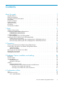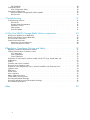
1
HP StorageWorks
All-in-One SB600c Storage Blade Solution
user guide
452693001
Part number: 452693–001
First edition: September 2007
Legal and notice information
© Copyright 2007 Hewlett-Packard Development Company, L.P.
The information contained herein is subject to change without notice. The only warranties for HP products and services are set forth
in the express warranty statements accompanying such products and services. Nothing herein should be construed as constituting
an additional warranty. HP shall not be liable for technical or editorial errors or omissions contained herein.
Microsoft, Windows, Windows XP, and Windows NT are U.S. registered trademarks of Microsoft Corporation.
Printed in the US
Contents
About this guide
. . . . . . . . . . . . . . . . . . . . . . . . . .
Intended audience . . . . . . .
Related documentation . . . . .
Document conventions and symbols
Rack stability . . . . . . . . .
HP technical support . . . . . .
Product warranties . . . . . . .
Subscription service . . . . . .
HP websites . . . . . . . . . .
Documentation feedback . . . .
. . .
. . .
. .
. . .
. . .
. . .
. . .
. . .
. . .
.
.
.
.
.
.
.
.
.
.
.
.
.
.
.
.
.
.
.
.
.
.
.
.
.
.
.
.
.
.
.
.
.
.
.
.
.
.
.
.
.
.
.
.
.
.
.
.
.
.
.
.
.
.
.
.
.
.
.
.
.
.
.
.
.
.
.
.
.
.
.
.
.
.
.
.
.
.
.
.
.
.
.
.
.
.
.
.
.
.
.
.
.
.
.
.
.
.
.
.
.
.
.
.
.
.
.
.
.
.
.
.
.
.
.
.
.
.
.
.
.
.
.
.
.
.
.
.
.
.
.
.
.
.
.
.
.
.
.
.
.
.
.
.
.
.
.
.
.
.
.
.
.
.
.
.
.
.
.
.
.
.
.
.
.
.
.
.
.
.
.
.
.
.
.
.
.
.
.
.
.
.
.
.
.
.
.
.
.
.
.
.
.
.
.
.
.
.
.
.
.
.
.
.
.
.
.
.
.
.
.
.
.
.
.
.
.
.
.
.
.
.
.
.
.
.
.
.
.
.
.
.
.
.
.
.
.
.
.
.
.
.
.
.
.
.
.
.
.
.
.
.
7
7
7
8
8
9
9
9
9
9
1 Setup . . . . . . . . . . . . . . . . . . . . . . . . . . . . . .
11
2 Operations . . . . . . . . . . . . . . . . . . . . . . . . . . .
19
Shipping carton contents . . . . . . . . . . . . . . .
Installing an HP BladeSystem c-Class enclosure . . . . . .
HP BladeSystem c7000 Enclosure . . . . . . . . .
HP BladeSystem c3000 Enclosure . . . . . . . . .
Installation guidelines . . . . . . . . . . . . . . . .
HP AiO SB600c Server and Storage Blades . . . . .
Installing the HP AiO SB600c Server and Storage Blades .
Installing interconnect modules . . . . . . . . . . .
Interconnect bay numbering and device mapping for the
Interconnect bay numbering and device mapping for the
. . . . . . . . . . .
. . . . . . . . . . .
. . . . . . . . . . .
. . . . . . . . . . .
. . . . . . . . . . .
. . . . . . . . . . .
. . . . . . . . . . .
. . . . . . . . . . .
c7000 Blade enclosure
c3000 Blade enclosure
Powering up the HP All-in-One SB600c Storage Blade Solution .
Powering down the HP All-in-One SB600c Storage Blade Solution
Virtual Power Button . . . . . . . . . . . . . . . . .
Manual Power Button . . . . . . . . . . . . . . . . .
Removing the HP AiO SB600c Server Blade . . . . . . . . .
Removing the access panel . . . . . . . . . . . . . . . .
Installing the access panel . . . . . . . . . . . . . . . .
.
.
.
.
.
.
.
.
.
.
.
.
.
.
.
.
.
.
.
.
.
.
.
.
.
.
.
.
.
.
.
.
.
.
.
.
.
.
.
.
.
.
.
.
.
.
.
.
.
.
.
.
.
.
.
.
.
.
.
.
.
.
.
.
.
.
.
.
.
.
.
.
.
.
.
.
.
.
.
.
.
.
.
.
.
.
.
.
.
.
.
.
.
.
.
.
.
.
.
.
.
.
.
.
.
.
.
.
.
.
.
.
.
.
.
.
.
.
.
.
.
.
.
.
.
.
.
.
.
.
.
.
.
.
.
.
.
.
.
.
.
.
.
.
.
.
.
.
.
.
.
.
.
.
.
.
.
.
.
.
.
.
.
.
.
.
.
.
.
.
.
.
.
.
.
.
.
.
.
.
.
.
3 Hardware Options installation and cabling . . . . . . . . . . . . .
Introduction . . . . . . . . . .
Processor option . . . . . . . .
Memory options . . . . . . . .
Installing FBDIMMs . . . .
Mezzanine card option . . .
Cabling . . . . . . . . . . .
Using the local I/O cable . .
Connecting locally to a server
Accessing a server blade
Accessing a server blade
4 Configuration utilities
. . . . . . . . . . . . . . .
. . . . . . . . . . . . . . .
. . . . . . . . . . . . . . .
. . . . . . . . . . . . . . .
. . . . . . . . . . . . . . .
. . . . . . . . . . . . . . .
. . . . . . . . . . . . . . .
blade with video and USB devices
with local KVM . . . . . . . .
with local media devices . . . .
.
.
.
.
.
.
.
.
.
.
.
.
.
.
.
.
.
.
.
.
.
.
.
.
.
.
.
.
.
.
.
.
.
.
.
.
.
.
.
.
.
.
.
.
.
.
.
.
.
.
.
.
.
.
.
.
.
.
.
.
.
.
.
.
.
.
.
.
.
.
.
.
.
.
.
.
.
.
.
.
.
.
.
.
.
.
.
.
.
.
.
.
.
.
.
.
.
.
.
.
.
.
.
.
.
.
.
.
.
.
.
.
.
.
.
.
.
.
.
.
.
.
.
.
.
.
.
.
.
.
.
.
.
.
.
.
.
.
.
.
. . . . . . . . . . . . . . . . . . . . . .
. . 11 . . 11 . . 11 .
12 .
12 .
13 .
13 .
17 .
17
.
18
.
.
.
.
.
.
.
.
.
.
.
.
.
.
.
.
.
iLO 2 . . . . . . . . . . . . . . . . . . . . . . . . . . . . . . . . . . . . . . . . . .
System Recovery DVD . . . . . . . . . . . . . . . . . . . . . . . . . . . . . . . . . . .
iLO 2 virtual DVD-ROM . . . . . . . . . . . . . . . . . . . . . . . . . . . . . . . . .
All-in-One SB600c Storage Blade Solution
19
19
20
20
20
21
22
23 23
23
31
31
31
33
33
33
33
34
37 37 37 38 3
USB DVD-ROM . . . . . . . . . . .
Configuration tools . . . . . . . . . . . .
Array Configuration Utility . . . . . .
Keeping the system current . . . . . . . .
All-in-One SB600c Storage Blade Solution
HP Care Pack . . . . . . . . . . . .
. . . .
. . . .
. . . .
. . . .
updates
. . . .
.
.
.
.
.
.
.
.
.
.
.
.
.
.
.
.
.
.
.
.
.
.
.
.
.
.
.
.
.
.
.
.
.
.
.
.
.
.
.
.
.
.
.
.
.
.
.
.
.
.
.
.
.
.
.
.
.
.
.
.
.
.
.
.
.
.
.
.
.
.
.
.
.
.
.
.
.
.
.
.
.
.
.
.
.
.
.
.
.
.
.
.
.
.
.
.
.
.
.
.
.
.
.
.
.
.
.
.
.
.
.
.
.
.
.
.
.
.
.
.
.
.
.
.
.
.
5 Troubleshooting . . . . . . . . . . . . . . . . . . . . . . . . . .
Troubleshooting resources . . . .
HP web site . . . . . . . .
Storage system documentation
Subscriber’s Choice . . . .
White papers . . . . . . .
Firmware updates . . . . .
.
.
.
.
.
.
.
.
.
.
.
.
.
.
.
.
.
.
.
.
.
.
.
.
.
.
.
.
.
.
.
.
.
.
.
.
.
.
.
.
.
.
.
.
.
.
.
.
.
.
.
.
.
.
.
.
.
.
.
.
.
.
.
.
.
.
.
.
.
.
.
.
.
.
.
.
.
.
.
.
.
.
.
.
.
.
.
.
.
.
.
.
.
.
.
.
.
.
.
.
.
.
.
.
.
.
.
.
.
.
.
.
.
.
.
.
.
.
.
.
.
.
.
.
.
.
.
.
.
.
.
.
.
.
.
.
.
.
.
.
.
.
.
.
.
.
.
.
.
.
.
.
.
.
.
.
.
.
.
.
.
.
.
.
.
.
.
.
.
.
.
.
.
.
A All-in-One SB600c Storage Blade Solution components . . . . . . . .
HP All-in-One SB600c Server Blade LEDs .
HP All-in-One SB600c Storage Blade LEDs
SAS and SATA components . . . . . . .
System board components . . . . . . .
Mezzanine connector definitions . . .
System maintenance switches . . . .
.
.
.
.
.
.
.
.
.
.
.
.
.
.
.
.
.
.
.
.
.
.
.
.
.
.
.
.
.
.
.
.
.
.
.
.
.
.
.
.
.
.
.
.
.
.
.
.
.
.
.
.
.
.
.
.
.
.
.
.
.
.
.
.
.
.
.
.
.
.
.
.
.
.
.
.
.
.
.
.
.
.
.
.
.
.
.
.
.
.
.
.
.
.
.
.
.
.
.
.
.
.
.
.
.
.
.
.
.
.
.
.
.
.
.
.
.
.
.
.
.
.
.
.
.
.
.
.
.
.
.
.
.
.
.
.
.
.
.
.
.
.
.
.
.
.
.
.
.
.
.
.
.
.
.
.
.
.
.
.
.
.
B Regulatory Compliance Notices and Safety . . . . . . . . . . . . . .
Regulatory compliance identification numbers . . . . . . . . . . . . . . . .
Federal Communications Commission notice . . . . . . . . . . . . . . . . .
FCC rating label . . . . . . . . . . . . . . . . . . . . . . . . . . .
Class A Equipment . . . . . . . . . . . . . . . . . . . . . . . . . .
Class B Equipment . . . . . . . . . . . . . . . . . . . . . . . . . .
Declaration of conformity for products marked with the FCC logo, United States only
Modifications . . . . . . . . . . . . . . . . . . . . . . . . . . . . . .
Cables . . . . . . . . . . . . . . . . . . . . . . . . . . . . . . . . .
Canadian notice (Avis Canadien) . . . . . . . . . . . . . . . . . . . . .
European Union regulatory notice . . . . . . . . . . . . . . . . . . . . .
Disposal of waste equipment by users in private households in the European Union
Japanese notice . . . . . . . . . . . . . . . . . . . . . . . . . . . . .
BSMI notice . . . . . . . . . . . . . . . . . . . . . . . . . . . . . . .
Korean notice . . . . . . . . . . . . . . . . . . . . . . . . . . . . . .
Laser compliance . . . . . . . . . . . . . . . . . . . . . . . . . . . .
Battery replacement notice . . . . . . . . . . . . . . . . . . . . . . . .
Taiwan battery recycling notice . . . . . . . . . . . . . . . . . . . . . .
Preventing electrostatic discharge . . . . . . . . . . . . . . . . . . . . . .
Grounding methods to prevent electrostatic discharge . . . . . . . . . . . . .
Environmental specifications . . . . . . . . . . . . . . . . . . . . . . . .
.
.
.
.
.
.
.
.
.
.
.
.
.
.
.
.
.
.
.
.
.
.
.
.
.
.
.
.
.
.
.
.
.
.
.
.
.
.
.
.
.
.
.
.
.
.
.
.
.
.
.
.
.
.
.
.
.
.
.
.
.
.
.
.
.
.
.
.
.
.
.
.
.
.
.
.
.
.
.
.
.
.
.
.
.
.
.
.
.
.
.
.
.
.
.
.
.
.
.
.
.
.
.
.
.
.
.
.
.
.
.
.
.
.
.
.
.
.
.
.
.
.
.
.
.
.
.
.
.
.
.
.
.
.
.
.
.
.
.
.
.
.
.
.
.
.
.
.
.
.
.
.
.
.
.
.
.
.
.
.
Index . . . . . . . . . . . . . . . . . . . . . . . . . . . . . .
4
.
.
.
.
.
.
.
.
.
.
.
.
.
.
.
.
.
.
.
.
38
38
38
39
39
39
41
41
41
41
41
41
41
43 43
45
46
48
49
49
51 51
51
51
52
52
52
52
52
53
53
53
54
54
54
55
55
55
56
56
57
59
Figures
1 ..c7000 Enclosure half-height device bay numbering . . . . . . . . . . . . . . . . .
12 2 ..c3000 Enclosure half-height device bay numbering . . . . . . . . . . . . . . . . .
12 3 ..c7000 Blade enclosure interconnect bay numbering . . . . . . . . . . . . . . . . .
17 4 ..c3000 Blade enclosure interconnect bay numbering
. . . . . . . . . . . . . . . .
18 5 ..Installing FBDIMMs . . . . . . . . . . . . . . . . . . . . . . . . . . . . . . .
31 6 ..Removing the mezzanine connector cover . . . . . . . . . . . . . . . . . . . . .
32 7 ..Installing the mezzanine card. . . . . . . . . . . . . . . . . . . . . . . . . . .
32 8 ..Connecting with a local KVM . . . . . . . . . . . . . . . . . . . . . . . . . .
34 9 ..Connecting with local media devices . . . . . . . . . . . . . . . . . . . . . . .
35 10 ..HP All-in-One SB600c Server Blade LEDs . . . . . . . . . . . . . . . . . . . . .
11 ..HP All-in-One SB600c Storage Blade LEDs . . . . . . . . . . . . . . . . . . . . .
43 45 12 ..SAS and SATA device numbers . . . . . . . . . . . . . . . . . . . . . . . . .
13 ..SAS and SATA hard drive LEDs . . . . . . . . . . . . . . . . . . . . . . . . .
14 ..System board components . . . . . . . . . . . . . . . . . . . . . . . . . . . .
46 46 48 All-in-One SB600c Storage Blade Solution
5
Tables
1 ..Document conventions . . . . . . . . . . . . . . . . . . . . . . . . . . . . . . 8 2 ..Interconnect bay numbering and device mapping c7000 Blade enclosure . . . . . . .
18
6
3 ..Interconnect bay numbering and device mapping ports c3000 Blade enclosure . . . . .
18
4 ..Local KVM connection components . . . . . . . . . . . . . . . . . . . . . . . .
34 5 ..USB Hub devices . . . . . . . . . . . . . . . . . . . . . . . . . . . . . . .
6 ..HP All-in-One SB600c Server Blade LEDs . . . . . . . . . . . . . . . . . . . . .
7 ..HP All-in-One SB600c Storage Blade LEDs . . . . . . . . . . . . . . . . . . . . .
35 44 45 8 ..SAS and SATA hard drive LEDs . . . . . . . . . . . . . . . . . . . . . . . . .
9 ..SAS and SATA hard drive LED combinations . . . . . . . . . . . . . . . . . . . .
10 ..System board components . . . . . . . . . . . . . . . . . . . . . . . . . . . .
46 47 48 11 ..FBDIMM slot numbering
. . . . . . . . . . . . . . . . . . . . . . . . . . . .
49 12 ..Mezzanine connector definitions . . . . . . . . . . . . . . . . . . . . . . . . .
13 ..System maintenance switches . . . . . . . . . . . . . . . . . . . . . . . . . .
49 49 14 ..Disposal of waste equipement . . . . . . . . . . . . . . . . . . . . . . . . . .
53 15 ..Battery replacement notice
. . . . . . . . . . . . . . . . . . . . . . . . . . .
55 16 ..Environmental specifications . . . . . . . . . . . . . . . . . . . . . . . . . . .
57 About this guide
This guide provides information about:
• All-in-One SB600c Storage Blade Solution
Intended audience
HP assumes you are qualified in the servicing of computer equipment and trained in recognizing hazards
in products with hazardous energy levels. This guide is intended for IT administrators with knowledge of:
• installation of servers and storage systems
• administration of servers and storage systems
• troubleshooting servers and storage systems
Related documentation
The following documents provide related information:
•
•
•
•
•
HP
HP
HP
HP
HP
BladeSystem Onboard Administrator user guide
Integrated Lights-Out 2 user guide
BladeSystem c3000 enclosure setup and installation guide
BladeSystem c7000 enclosure setup and installation guide
Proliant Blade troubleshooting guide
You can find these documents from the Manuals page of the HP Business Support Center website:
http://www.hp.com/support/manuals
In the Storage section, click Disk Storage Systems and then select your product.
All-in-One SB600c Storage Blade Solution
7
Document conventions and symbols
Table 1 Document conventions
Convention
Element
Blue text: Table 1
Cross-reference links and e-mail addresses
Blue, underlined text: http://www.hp.com
website addresses
Bold text
• Keys that are pressed
• Text typed into a GUI element, such as a box
• GUI elements that are clicked or selected, such as
menu and list items, buttons, tabs, and check boxes
Italic text
Text emphasis
Monospace text
•
•
•
•
Monospace, italic text
• Code variables
• Command variables
Monospace, bold text
Emphasized monospace text
File and directory names
System output
Code
Commands, their arguments, and argument values
WARNING!
Indicates that failure to follow directions could result in bodily harm or death.
CAUTION:
Indicates that failure to follow directions could result in damage to equipment or data.
IMPORTANT:
Provides clarifying information or specific instructions.
NOTE:
Provides additional information.
TIP:
Provides helpful hints and shortcuts.
Rack stability
Rack stability protects personnel and equipment.
8
About this guide
WARNING!
To
•
•
•
•
•
reduce the risk of personal injury or damage to equipment:
Extend leveling jacks to the floor.
Ensure that the full weight of the rack rests on the leveling jacks.
Install stabilizing feet on the rack.
In multiple-rack installations, fasten racks together securely.
Extend only one rack component at a time. Racks can become unstable if more than one component
is extended.
HP technical support
For worldwide technical support information, see the HP support website:
http://www.hp.com/support
Before contacting HP, collect the following information:
•
•
•
•
•
•
Product model names and numbers
Technical support registration number (if applicable)
Product serial numbers
Error messages
Operating system type and revision level
Detailed questions
Product warranties
For information about HP StorageWorks product warranties, see the warranty information website:
http://www.hp.com/go/storagewarranty
Subscription service
HP recommends that you register your product at the Subscriber’s Choice for Business website:
http://www.hp.com/go/e-updates
After registering, you will receive e-mail notification of product enhancements, new driver versions,
firmware updates, and other product resources.
HP websites
For additional information, see the following HP websites:
•
•
•
•
•
http://www.hp.com
http://www.hp.com/go/storage
http://www.hp.com/service_locator
http://www.hp.com/support/manuals
http://www.hp.com/support/downloads
Documentation feedback
HP welcomes your feedback.
All-in-One SB600c Storage Blade Solution
9
To make comments and suggestions about product documentation, please send a message to
[email protected]. All submissions become the property of HP.
10
About this guide
1 Setup
In this section:
•
•
•
•
Shipping carton contents
Installing an HP BladeSystem c-Class enclosure
Installation guidelines
Installing the HP AiO SB600c Server and Storage Blades
Shipping carton contents
When unpacking the HP All-in-One SB600c Storage Blade Solution, check for the following items:
•
•
•
•
•
•
HP Storageworks SB600c server blade
HP StorageWorks SB600c storage blade
Local I/O cable
Documentation Kit, Safety and Disposal Documentation CD
HP StorageWorks AiO Storage Blade System Recovery DVD
End User License Agreement
Documentation is also available in the following locations:
• Documentation CD that ships with the enclosure
• HP Business Support Center website http://www.hp.com/support
• HP Technical Documentation websitehttp://docs.hp.com
Installing an HP BladeSystem c-Class enclosure
Before performing any procedures specific to the HP AiO SB600c Storage Blade Solution, install
an HP BladeSystem c-Class enclosure.
IMPORTANT:
If your HP AiO SB600c Storage Blade Solution is factory-integrated, the server and storage blades are
pre-installed in an HP BladeSystem c-Class enclosure. For instructions on connecting the enclosure to the
network and powering it on, see the installation guides that are shipped with the enclosures.
HP BladeSystem c7000 Enclosure
The colors correspond to a partner bay; for example 1 and 2 are in one partner bay.
All-in-One SB600c Storage Blade Solution
11
Figure 1 c7000 Enclosure half-height device bay numbering
HP BladeSystem c3000 Enclosure
The colors correspond to a partner bay; for example 1 and 2 are in one partner bay.
Figure 2 c3000 Enclosure half-height device bay numbering
Installation guidelines
Observe the following guidelines when installing the server and storage blades for the HP AiO SB600c:
• Install the storage blade prior to installing the server blade
• Before installing and initializing the server blade, install any server blade options, such as an
additional processor or mezzanine card.
Onboard Administrator is used to configure the enclosure and the HP AiO SB600c. To function with the
HP AiO SB600c, Onboard Administrator version 1.30 or later is required.
12
Setup
HP AiO SB600c Server and Storage Blades
SB600c server and storage blades support each other in partner bays. Each partner bay will hold one
server blade and one storage blade.
• If the storage blade is installed in an odd-numbered bay, install the partner server blade in
the adjacent even-numbered bay to the right.
• If the storage blade is installed in an even-numbered bay, install the partner server blade in
the adjacent odd-numbered bay to the left.
Installing the HP AiO SB600c Server and Storage Blades
IMPORTANT:
Install the storage blade prior to installing the server blade.
CAUTION:
To prevent improper cooling and thermal damage, do not operate the server blade or the enclosure
unless all hard drive and device bays are populated with either a component or a blank.
1. Remove the blank.
2. Remove the enclosure connector cover.
All-in-One SB600c Storage Blade Solution
13
3. Open the locking clip at the bottom of the front panel of the storage blade.
4. Install the storage blade by inserting it fully into one of the two partner bays, and closing the
locking clip.
14
Setup
5. Remove a second blank from the adjacent partner bay.
6. Remove the enclosure connector cover from the server blade and the Product Licenses Agreement
label.
All-in-One SB600c Storage Blade Solution
15
7. Open the locking clip on the left side of the server blade.
8. Install the server blade by inserting it fully into the device bay and closing the locking clip.
16
Setup
Installing interconnect modules
For specific steps to install interconnect modules, see the documentation that ships with the interconnect
module.
Interconnect bay numbering and device mapping for the c7000 Blade enclosure
Figure 3 c7000 Blade enclosure interconnect bay numbering
To support network connections for specific signals, install an interconnect module in the bay
corresponding to the embedded NIC or mezzanine signals.
All-in-One SB600c Storage Blade Solution
17
Table 2 Interconnect bay numbering and device mapping c7000 Blade enclosure
Server blade signal
Interconnect bay
NIC 1 (Embedded)
1
NIC 2 (Embedded)
2
Mezzanine 1
3 and 4
Mezzanine 2
5 and 6
Interconnect bay labels
7 and 8
Interconnect bay numbering and device mapping for the c3000 Blade enclosure
Figure 4 c3000 Blade enclosure interconnect bay numbering
Table 3 Interconnect bay numbering and device mapping ports c3000 Blade enclosure
Server blade
signal
Interconnect
bay number
NICs 1, 2
(embedded)
1
—
Mezzanine 1
2
Four port cards connect to bay 2
Mezzanine 2
3,4
Four port cards; Ports 1 and
3 connect to bay 3. 2 and 4
connect to bay 4.
Interconnect bay label
Notes
For detailed port mapping information, see theHP BladeSystem Enclosure installation poster or the
HP BladeSystem Enclosure setup and installation guide at http://www.hp.com/go/bladesystem/
documentation
18
Setup
2 Operations In this section:
•
•
•
•
•
Powering up the HP All-in-One SB600c Storage Blade Solution
Powering down the HP All-in-One SB600c Storage Blade Solution
Removing the HP AiO SB600c Server Blade
Removing the access panel
Installing the access panel
Powering up the HP All-in-One SB600c Storage Blade Solution
1. Ensure the server blade is powered down.
2. Install the HP AiO SB600c storage blade.
See Installing the HP AiO SB600c Server and Storage Blades on page 13 for installing storage
blades.
3. After the storage blade is installed, the system health LED flashes amber.
4. Install the server blade.
See Installing the HP AiO SB600c Server and Storage Blades on page 13 for installing server blades.
5. The Onboard Administrator initiates an automatic power-up sequence when the server blades
are installed. If the default setting is changed, use one of the following methods to power
up the server blade:
• Use a virtual power button selection through iLO 2.
• Select the virtual power button on the Onboard Administrator interface.
• Press and release the Power On/Standby button on the server blade.
6. When the server blade goes from the standby mode to the full power mode, the system power
LED changes from amber to green.
For more information about the Onboard Administrator, see HP BladeSystem Onboard Administrator
user guide.
For more information about iLO 2, see iLO 2 on page 37 for more information.
Powering down the HP All-in-One SB600c Storage Blade
Solution
Two different methods are available to power down the HP AiO SB600c Storage Blade Solution, a virtual
power button and a power button located on the HP AiO SB600c Server Blade.
The preferred method for closing down the HP AiO SB600c is using the virtual power button through
OnBoard Administrator.
NOTE:
Before powering down the HP AiO SB600c for any upgrade or maintenance procedures, perform
a backup of critical server data and programs.
All-in-One SB600c Storage Blade Solution
19
IMPORTANT:
When the server blade is in standby mode, auxiliary power is still being provided. To remove all power
from the server blade, remove the server blade from the enclosure.
To power down the HP AiO SB600c, first power down the HP AiO SB600c Server Blade. Depending on
the Onboard Administrator configuration, use one of the following methods to power down the server
blade, the virtual power button or the manual power button located on the server blade.
Virtual Power Button
Two ways are available to access the virtual power button, either through the Onboard Administrator
interface or through iLO 2.
• Select the virtual power button through the Onboard Administrator interface. (Preferred method)
• Use a virtual power button selection through iLO 2.
This method initiates a controlled remote shutdown of applications and the OS before the server blade
enters standby mode. You must be logged into the server to complete this task.
Manual Power Button
The manual Power On/Standby button is located on the server blade.
• Press and release the Power On/Standby button.
This method initiates a controlled shutdown of applications and the OS before the server blade enters
standby mode. You must be logged into the server to complete this task
• Press and hold the Power On/Standby button for more than 4 seconds to force the server
blade to shut down.
CAUTION:
This method should only be used when no other shut down methods are available. Applications and
files could be permanently corrupted from this method.
This method forces the server blade to enter standby mode without properly exiting applications and
the OS. It provides an emergency shutdown method in the event of a hung application.
After initiating a virtual power down command, be sure that the server blade goes into standby mode
by observing that the system power LED is amber.
Removing the HP AiO SB600c Server Blade
To remove the component:
1. Identify the proper server blade.
2. Power down the server blade.
See Powering down the HP All-in-One SB600c Storage Blade Solution on page 19 for more
information.
3. Ensure the server is completely off before removing the blade from the chassis.
4. Open the locking clip located on the lower left of the server blade.
20
Operations
5. Remove the server blade from the chassis.
6. Place the server blade on a flat, level work surface.
WARNING!
To reduce the risk of personal injury from hot surfaces, allow the drives and the internal system
components to cool before touching them.
CAUTION:
To prevent damage to electrical components, properly ground the server blade before beginning any
installation procedure. Improper grounding can cause Electrostatic Discharge (ESD).
Removing the access panel
To remove the component:
1. Power down the server blade.
See Powering down the HP All-in-One SB600c Storage Blade Solution on page 19 for more
information.
2. Remove the server blade.
See Installing the HP AiO SB600c Server and Storage Blades on page 13 for more information.
3. Lift the access panel latch and slide the access panel to the rear.
4. Remove the access panel.
WARNING!
To reduce the risk of personal injury from hot surfaces, allow the drives and the internal system
components to cool before touching them.
All-in-One SB600c Storage Blade Solution
21
CAUTION:
To prevent damage to electrical components, properly ground the server blade before beginning any
installation procedure. Improper grounding can cause ESD.
Installing the access panel
1. Place the access panel on top of the server blade with the hood latch open. Allow the panel to
extend past the rear of the server blade approximately 0.8 cm (0.2 in).
2. Engage the anchoring pin with the corresponding hole in the latch.
3. Push down on the hood latch. The access panel slides to a closed position.
22
Operations
3 Hardware Options installation
and cabling
In this section
•
•
•
•
Introduction
Processor option
Memory options
Cabling
Introduction
The following gives information for installing components and cabling for the HP All-in-One SB600c
Storage Solution.
WARNING!
If more than one option is being installed, read the installation instructions for all the hardware options
and identify similar steps to streamline the installation process.
CAUTION:
To prevent damage to electrical components, properly ground the server before beginning any installation
procedure. Improper grounding can cause electrostatic discharge.
Processor option
WARNING!
To reduce the risk of personal injury from hot surfaces, allow the drives and the internal system
components to cool before touching them.
CAUTION:
To avoid damage to the system board:
• Do not touch the processor socket contacts.
• Always install the processor socket cover after removing the processor from the socket.
• Do not tilt or slide the processor when lowering the processor into the socket.
CAUTION:
To avoid damage to the processor:
• Handle the processor only by the edges.
• Do not touch the bottom of the processor, especially the contact area.
All-in-One SB600c Storage Blade Solution
23
CAUTION:
To prevent possible server malfunction and damage to the equipment, multiprocessor configurations must
contain processors with the same part number.
CAUTION:
To prevent possible server blade overheating, always populate processor socket 2 with a processor and a
heatsink or a processor cover and a heatsink blank.
CAUTION:
The heatsink thermal interface media is not reusable and must be replaced if the heatsink is removed
from the processor after it has been installed.
IMPORTANT:
When installing the heatsink, align the guide pins on the processor retention bracket with the alignment
holes in the heatsink.
IMPORTANT:
Processor socket 1 must always be populated. If processor socket 1 is empty, the server blade does not
power up.
NOTE:
Do not discard the processor protective cover. Always install the processor protective cover if the
processor is removed from the socket.
To install the component:
1. Power down the server blade.
See Powering down the HP All-in-One SB600c Storage Blade Solution on page 19 for more
information.
2. Remove the server blade.
See Removing the HP AiO SB600c Server Blade on page 20 for more information.
3. Remove the access panel.
See Removing the access panel on page 21 for more information.
4. Remove all hard drives.
5. Remove the hard drive backplane.
24
Hardware Options installation and cabling
6. Remove the front panel/hard drive cage assembly.
7. Remove the heatsink blank. Retain the heatsink blank for future use.
All-in-One SB600c Storage Blade Solution
25
8. Open the processor retaining latch and the processor socket retaining bracket.
9. Remove the processor socket protective cover.
26
Hardware Options installation and cabling
10. If the processor has separated from the installation tool, carefully re-insert the processor in the tool.
11. Align the processor installation tool with the socket and install the processor.
All-in-One SB600c Storage Blade Solution
27
12. Press down firmly until the processor installation tool clicks and separates from the processor, and
then remove the processor installation tool.
13. Close the processor socket retaining bracket and the processor retaining latch.
28
Hardware Options installation and cabling
14. Remove the thermal interface protective cover from the heatsink.
15. Install the heatsink.
IMPORTANT:
Be sure the processor remains inside the processor installation tool.
All-in-One SB600c Storage Blade Solution
29
CAUTION:
Heatsink retaining screws should be tightened in diagonally opposite pairs (in an "X"
pattern).
16. Install the front panel/hard drive cage assembly.
17. Install the hard drive backplane. Press down on the connector to seat the board.
18. Install the hard drives.
19. Install the access panel. See Installing the access panel on page 22 for more information.
20. Install the server blade. See Installing the HP AiO SB600c Server and Storage Blades on page 13
for more information.
30
Hardware Options installation and cabling
Memory options
The HP AiO SB600c Server Blade is configured with 2 GB of memory. The server contains eight FBDIMM
slots and the Operating System can address up to 4 GB of memory. Using the Advanced Memory
Protection options will allow 4 GB more of memory to be used as an online spare or mirrored memory.
See http://www.hp.com for more information.
Installing FBDIMMs
To install the component:
1. Power down the server blade.
See Powering down the HP All-in-One SB600c Storage Blade Solution on page 19 for more
information.
2. Remove the server blade. See Removing the HP AiO SB600c Server Blade on page 20 for more
information.
3. Remove the access panel. See 21 for more information.
4. Install the FBDIMM.
Figure 5 Installing FBDIMMs
5. Install the access panel. See Installing the access panel on page 22 for more information.
6. Install the server blade.
See Installing the HP AiO SB600c Server and Storage Blades on page 13 for more information.
7. Power up the server blade.
See Powering up the HP All-in-One SB600c Storage Blade Solution on page 19 for more information.
Mezzanine card option
Optional mezzanine cards are classified as Type I mezzanine cards and Type II mezzanine cards.
The card type determines where it can be installed in the server blade. Optional mezzanine cards
enable network connectivity and provide Fibre Channel support. For mezzanine card locations, see
System board components on page 48 for more information.
• Install Type I mezzanine cards on either mezzanine 1 connector or mezzanine 2 connector.
All-in-One SB600c Storage Blade Solution
31
• Install Type II mezzanine cards only on mezzanine 2 connector.
To install the component:
1. Power down the server blade.
See 19 for more information.
2. Remove the server blade.
See Removing the HP AiO SB600c Server Blade on page 20 for more information.
3. Remove the access panel. See Removing the access panel on page 21 for more information.
4. Remove the mezzanine connector cover.
Figure 6 Removing the mezzanine connector cover
5. Install the mezzanine card. Press down on the connector to seat the board.
Figure 7 Installing the mezzanine card.
6. Install the access panel. See Installing the access panel on page 22
32
Hardware Options installation and cabling
7. Install the server blade. See Installing the HP AiO SB600c Server and Storage Blades on page 13
Cabling
In this section
• Using the local I/O cable
• Connecting locally to a server blade with video and USB devices
Using the local I/O cable
The local I/O cable enables the user to perform server blade administration, configuration, and
diagnostic procedures by connecting video and USB devices directly to the server blade.
Connecting locally to a server blade with video and USB devices
Use the local I/O cable to connect a monitor and any of the following USB devices:
•
•
•
•
•
USB
USB
USB
USB
USB
hub
keyboard
mouse
DVD-ROM drive
diskette drive
Multiple configurations are possible. This section offers two possible configurations.
Accessing a server blade with local KVM
CAUTION:
Before disconnecting the local I/O cable from the connector, always squeeze the release buttons on the
sides of the connector. Failure to do so can result in damage to the equipment.
NOTE:
For this configuration, a USB hub is not necessary. To connect additional devices, use a USB hub.
1. Connect the local I/O cable to the server blade.
2. Connect the video connector to a monitor.
3. Connect a USB mouse to one USB connector.
4. Connect a USB keyboard to the second USB connector.
All-in-One SB600c Storage Blade Solution
33
Figure 8 Connecting with a local KVM
Table 4 Local KVM connection components
Item
Description
1
Monitor
2
USB mouse
3
USB keyboard
4
Local I/O cable
Accessing a server blade with local media devices
Use the following configuration when configuring a server blade or loading software updates and
patches from a USB DVD-ROM or a USB diskette.
1. Connect the local I/O cable to the server blade.
2. Connect the video connector to a monitor.
3. Connect a USB hub to one USB connector.
4. Connect the following to the USB hub:
• USB DVD-ROM drive
• USB keyboard
• USB mouse
• USB diskette
34
Hardware Options installation and cabling
NOTE:
Use a USB hub when connecting a USB diskette drive and/or USB DVD-ROM drive to the server blade.
The USB hub provides additional connections.
Figure 9 Connecting with local media devices
Table 5 USB Hub devices
Item
Description
1
Monitor
2
USB DVD-ROM drive or diskette drive
3
USB keyboard
4
USB hub
5
USB mouse
6
Local I/O cable
NOTE:
For more information about hardware and cabling configurations, see the documents that ship with
the c-Class enclosures.
All-in-One SB600c Storage Blade Solution
35
36
Hardware Options installation and cabling
4 Configuration utilities
In this section
•
•
•
•
iLO 2
System Recovery DVD
Configuration tools
Keeping the system current
iLO 2
iLO 2 is a standard component of ProLiant c-Class server blades that provides server health and remote
server blade manageability. Its features are accessed from a network client device using a supported web
browser. In addition to other features, iLO 2 provides keyboard, mouse, and video (text and graphics)
capability for a server blade, regardless of the state of the host OS or host server blade.
iLO 2 includes an intelligent microprocessor, secure memory, and a dedicated network interface. This
design makes iLO 2 independent of the host server blade and its OS. iLO 2 provides remote access to
any authorized network client, sends alerts, and provides other server blade management functions.
Using a supported web browser, you can:
• Remotely access the console of the host server blade, including all text mode and graphics mode
screens with full keyboard and mouse controls.
• Remotely power up, power down, or reboot the host server blade.
• Remotely boot a host server blade to a virtual media image to perform a ROM upgrade or
install an OS.
• Send alerts from iLO 2 regardless of the state of the host server blade.
• Access advanced troubleshooting features provided by iLO 2.
• Launch a web browser, use SNMP alerting, and diagnose the server blade with HP SIM.
• Configure static IP bay settings for the dedicated iLO 2 management NICs on each server blade
in an enclosure for faster deployment.
To connect to the server blade using iLO 2, install the server blade in an enclosure. Onboard
Administrator assigns an IP address to enable iLO 2 connectivity to the server blade.
The c-Class tab enables you to control specific settings for the HP BladeSystem. iLO 2 also provides
web-based status for the HP BladeSystem configuration.
For detailed information about iLO 2, refer to the HP Integrated Lights-Out User Guide on the HP website
http://www.hp.com/servers/lights-out.
System Recovery DVD
The System Recovery DVD is used to restore the system to factory defaults. Keep this DVD in a safe place.
You may boot from the DVD and restore the system to the factory condition at any time. This allows you
to recover the system if all other means to boot the system fails. While the recovery process makes
every attempt to preserve the existing data volumes, you should have a backup of your data if at all
possible before recovering the system.
All-in-One SB600c Storage Blade Solution
37
WARNING!
During a recovery process, this DVD overwrites the original OS logical drives. All data on these
drives will be erased.
Two methods are available for system recovery:
• iLO virtual DVD-ROM
• USB DVD-ROM
NOTE:
Using iLO 2 virtual DVD-ROM to restore your system will take longer than the USB DVD-ROM method.
iLO 2 virtual DVD-ROM
This method uses iLO 2 virtual System Recovery DVD to restore your original OS.
To restore with an iLO 2 virtual System Recovery DVD:
1. Insert the System Restore DVD into the client PC that is using the iLO 2 Remote Console.
2. Remotely access the server blade through iLO 2.
3. Click the Virtual Devices tab.
4. Select Virtual Media.
5. Use the Virtual Media applet to select the local DVD or image file and connect the Virtual DVD to
the server blade.
6. Use the iLO 2 Virtual Power Button feature to reboot the server blade.
7. Follow the quick restore instructions
USB DVD-ROM
This method uses System Recovery DVD to restore your original OS.
To restore with the System Recovery DVD:
1. Use the local I/O cable to connect a USB DVD-ROM drive to the server blade.
See Accessing a server blade with local media devices on page 34
2. Insert the System Recovery DVD into the USB DVD-ROM drive.
3. Reboot the server blade.
4. After the server blade boots, follow the quick restore instructions.
Configuration tools
Array Configuration Utility
NOTE:
ACU does not support mixing SAS and SATA drives in the same logical volume.
ACU is a browser-based utility with the following features:
• Runs as a local application or remote service
38
Configuration utilities
• Supports online array capacity expansion, logical drive extension, assignment of online spares,
and RAID or stripe size migration
• Suggests the optimum configuration for an unconfigured system
• Provides different operating modes, enabling faster configuration or greater control over the
configuration options
• Remains available any time that the server is on
• Displays on-screen tips for individual steps of a configuration procedure
For optimum performance, the minimum display settings are 800 × 600 resolution and 256 colors.
Servers running Microsoft® operating systems require Internet Explorer 5.5 (with Service Pack 1) or later.
For more information, refer to the Configuring Arrays on HP Smart Array Controllers Reference Guide
on the Documentation CD or the HP website http://www.hp.com.
Keeping the system current
All-in-One SB600c Storage Blade Solution updates
Use care when applying operating system updates (service packs, hotfixes, and patches). Before
updating the operating system, read the release notes for each update. If you do not require specific fixes
from the update, HP recommends that you do not apply the updates.
If you decide to apply an operating system update:
1. Perform a full system backup.
2. Apply the operating system update, using the instructions provided.
3. Install the current drivers.
To obtain downloads for the All-in-One Storage Blade Solution, go to http://www.hp.com/go/
AiOstorage.
HP Care Pack
HP Care Pack Services offer upgraded service levels to extend and expand standard product warranty
with easy-to-buy, easy-to-use support packages that help you make the most of your server investments.
Refer to the Care Pack website http://www.hp.com/hps/carepack/servers/cp_proliant.html.
All-in-One SB600c Storage Blade Solution
39
40
Configuration utilities
5 Troubleshooting
Troubleshooting resources
The HP ProLiant Servers Troubleshooting Guide provides simple procedures for resolving common
problems as well as a comprehensive course of action for fault isolation and identification, error message
interpretation, issue resolution, and software maintenance.
To obtain the guide, refer to any of the following sources and then select the HP ProLiant Servers
Troubleshooting Guide:
• The Business Support Center on the http://www.hp.com/support. Navigate to the server
technical support page. Under self-help resources, select ProLiant Troubleshooting Guide.
• The Technical Documentation website http://www.docs.hp.com. Select Enterprise Servers,
Workstations and Systems Hardware, and then the appropriate server.
HP web site
Troubleshooting tools and information, as well as the latest drivers and flash ROM images, are available
at http://www.hp.com.
Storage system documentation
Storage system documentation is the set of documents provided with a storage system. Most storage
system documents are available as a PDF file or a link on the documentation CD. Storage system
documentation can be accessed from http://www.hp.com/support/manuals). Under the storage section,
click Disk Storage Systems and then select your product.
Subscriber’s Choice
HP Subscriber’s Choice is a customizable subscription sign-up service that customers use to receive
personalized e-mail product tips, feature articles, driver and support alerts, or other notifications.
To create a profile and select notifications, see http://www.hp.com/go/subscriberschoice.
White papers
White papers are electronic documents on complex technical topics. Some white papers
contain in-depth details and procedures. Topics include HP products, HP technology, operating
systems, networking products, and performance issues. See the HP Business Support Center at
http://www.hp.com/go/bizsupport.
Firmware updates
Firmware is software that is stored in Read-Only Memory (ROM). Firmware is responsible for the behavior
of the system when it is first switched on and for passing control of the server to the operating system.
When referring to the firmware on the system board of the server, it is called the System ROM or the
BIOS. When referring to the firmware on another piece of hardware configured in the server, it is called
Option ROM. These systems have hard drives and Smart Array Controller options that have firmware
that can be updated.
It is important to update the firmware (also called “flashing the ROM”) as part of regular server
maintenance. In addition, checking for specific firmware updates in between regular updates helps to
keep the server performing optimally. HP recommends checking for a firmware update before sending a
part back to HP for replacement.
All-in-One SB600c Storage Blade Solution
41
Apply the latest firmware and software updates using the HP All-in-One Service Release DVD. The DVD
provides software updates, upgrades, and enhancements for the storage system. The Service Release can
be ordered without cost from http://software.hp.com. On the web site, select the “Storage and NAS”
category. The latest service release version appears in the list of available software.
42
Troubleshooting
A All-in-One SB600c Storage Blade
Solution components
HP All-in-One SB600c Server Blade LEDs
Figure 10 HP All-in-One SB600c Server Blade LEDs
All-in-One SB600c Storage Blade Solution
43
Table 6 HP All-in-One SB600c Server Blade LEDs
Item
Description
Status
1
Hard drive bay 1
N/A
2
Power On/Standby button
N/A
3
Local I/O connector*
N/A
4
Hard drive bay 2
N/A
5
Server blade handle
N/A
6
Release button
N/A
7
NIC 2 LED*
Green = Network linked
Green flashing = Network activity
Off = No link or activity
8
NIC 1 LED*
Green = Network linked
Green flashing = Network activity
Off = No link or activity
9
Health LED
Green = Normal
Flashing = Booting
Amber = Degraded condition
Red= Critical condition
10
UID LED
Blue = Identified
Blue flashing = Active remote management
11
Serial pull tab
N/A
44
All-in-One SB600c Storage Blade Solution components
HP All-in-One SB600c Storage Blade LEDs
Figure 11 HP All-in-One SB600c Storage Blade LEDs
Table 7 HP All-in-One SB600c Storage Blade LEDs
Item
Description
Status
1
Serial Pull tab
N/A
2
Reserved
N/A
3
Reserved
N/A
4
Storage Blade Handle
N/A
5
UID LED
Blue = Identified
Off = Not identified
6
System Health LED
Green = Normal operation
Flashing amber = Degraded condition
Flashing red = Critical condition
All-in-One SB600c Storage Blade Solution
45
SAS and SATA components
Figure 12 SAS and SATA device numbers
Figure 13 SAS and SATA hard drive LEDs
Table 8 SAS and SATA hard drive LEDs
Item
Description
1
Fault/UID LED (amber/blue)
2
Online LED (green)
46
All-in-One SB600c Storage Blade Solution components
Table 9 SAS and SATA hard drive LED combinations
Online/activity
LED (green)
Fault/UID LED
(amber/blue)
Interpretation
On, off, or flashing
Alternating amber
and blue
The drive has failed, or a predictive failure alert has been
received for this drive; it also has been selected by a
management application.
On, off, or flashing
Steadily blue
The drive is operating normally, and it has been selected by
a management application.
On
Amber, flashing
regularly (1 Hz)
A predictive failure alert has been received for this drive.
Replace the drive as soon as possible.
On
Off
The drive is online, but it is not active currently.
Flashing regularly
(1 Hz)
Amber, flashing
regularly (1 Hz)
Do not remove the drive. Removing a drive may terminate
the current operation and cause data loss.The drive is part
of an array that is undergoing capacity expansion or stripe
migration, but a predictive failure alert has been received for
this drive. To minimize the risk of data loss, do not replace
the drive until the expansion or migration is complete.
Flashing regularly
(1 Hz)
Off
Do not remove the drive. Removing a drive may terminate the
current operation and cause data loss.The drive is rebuilding,
or it is part of an array that is undergoing capacity expansion
or stripe migration.
Flashing irregularly
Amber, flashing
regularly (1 Hz)
The drive is active, but a predictive failure alert has been
received for this drive. Replace the drive as soon as possible.
Flashing irregularly
Off
The drive is active, and it is operating normally.
Off
Steadily amber
A critical fault condition has been identified for this drive,
and the controller has placed it offline. Replace the drive as
soon as possible.
Off
Amber, flashing
regularly (1 Hz)
A predictive failure alert has been received for this drive.
Replace the drive as soon as possible.
Off
Off
The drive is offline, a spare, or not configured as part of an
array.
All-in-One SB600c Storage Blade Solution
47
System board components
Figure 14 System board components
Table 10 System board components
Item
Description
1
System board thumbscrew
2
Processor socket 2
3
Processor socket 1 (populated)
4
Hard drive backplane connector
5
FBDIMMs (8)
6
Embedded NICs (2)
7
Mezzanine connector 1 [Type I mezzanine only (shown)]
8
Battery
9
Mezzanine connector 2 [Type I (shown) or Type II mezzanine]
10
System maintenance switch (SW2)
11
System board thumbscrew
12
Enclosure connector
The symbols correspond to the symbols located on the interconnect bays.
48
All-in-One SB600c Storage Blade Solution components
Table 11 FBDIMM slot numbering
FBDIMM slots
Memory bank
Memory branch
1 and 3
A
0
5 and 7
B
1
2 and 4
C
0
6 and 8
D
1
Mezzanine connector definitions
Table 12 Mezzanine connector definitions
Item
PCIe
Mezzanine connector 1
x4, Type I mezzanine card only
Mezzanine connector 2
x8, Type 1 or II mezzanine card
A PCIe x4 mezzanine connector supports x8 cards at up to x4 speeds. A PCIe x8 mezzanine connector
supports x16 cards at up to x8 speeds.
System maintenance switches
Table 13 System maintenance switches
Position
Function
Default
1*
iLO 2 security override
Off
2
Configuration lock
Off
3
Reserved
Off
4
Reserved
Off
5*
Password disabled
Off
6*
Reset configuration
Off
7
Reserved
Off
8
Reserved
Off
*To access redundant ROM, set S1, S5, and S6 to ON.
All-in-One SB600c Storage Blade Solution
49
50
All-in-One SB600c Storage Blade Solution components
B Regulatory Compliance Notices
and Safety
In this section
•
•
•
•
•
•
•
•
•
•
•
•
•
•
•
•
•
Regulatory compliance identification numbers
Federal Communications Commission notice
Declaration of conformity for products marked with the FCC logo, United States only
Modifications
Cables
Canadian notice (Avis Canadien)
European Union regulatory notice
Disposal of waste equipment by users in private households in the European Union
Japanese notice
BSMI notice
Korean notice
Laser compliance
Battery replacement notice
Taiwan battery recycling notice
Preventing electrostatic discharge
Grounding methods to prevent electrostatic discharge
Environmental specifications
Regulatory compliance identification numbers
For the purpose of regulatory compliance certifications and identification, this product has been
assigned a unique regulatory model number. The regulatory model number can be found on the
product nameplate label, along with all required approval markings and information. When requesting
compliance information for this product, always refer to this regulatory model number. The regulatory
model number is not the marketing name or model number of the product.
Federal Communications Commission notice
Part 15 of the Federal Communications Commission (FCC) Rules and Regulations has established Radio
Frequency (RF) emission limits to provide an interference-free radio frequency spectrum. Many electronic
devices, including computers, generate RF energy incidental to their intended function and are, therefore,
covered by these rules. These rules place computers and related peripheral devices into two classes, A
and B, depending upon their intended installation. Class A devices are those that may reasonably be
expected to be installed in a business or commercial environment. Class B devices are those that may
reasonably be expected to be installed in a residential environment (for example, personal computers).
The FCC requires devices in both classes to bear a label indicating the interference potential of the device
as well as additional operating instructions for the user.
FCC rating label
The FCC rating label on the device shows the classification (A or B) of the equipment. Class B devices
have an FCC logo or ID on the label. Class A devices do not have an FCC logo or ID on the label. After
you determine the class of the device, refer to the corresponding statement.
All-in-One SB600c Storage Blade Solution
51
Class A Equipment
This equipment has been tested and found to comply with the limits for a Class A digital device, pursuant
to Part 15 of the FCC Rules. These limits are designed to provide reasonable protection against harmful
interference when the equipment is operated in a commercial environment. This equipment generates,
uses, and can radiate radio frequency energy and, if not installed and used in accordance with the
instructions, may cause harmful interference to radio communications. Operation of this equipment in a
residential area is likely to cause harmful interference, in which case the user will be required to correct
the interference at personal expense.
Class B Equipment
This equipment has been tested and found to comply with the limits for a Class B digital device, pursuant
to Part 15 of the FCC Rules. These limits are designed to provide reasonable protection against harmful
interference in a residential installation. This equipment generates, uses, and can radiate radio frequency
energy and, if not installed and used in accordance with the instructions, may cause harmful interference
to radio communications. However, there is no guarantee that interference will not occur in a particular
installation. If this equipment does cause harmful interference to radio or television reception, which
can be determined by turning the equipment off and on, the user is encouraged to try to correct the
interference by one or more of the following measures:
• Reorient or relocate the receiving antenna.
• Increase the separation between the equipment and receiver.
• Connect the equipment into an outlet on a circuit that is different from that to which the receiver is
connected.
• Consult the dealer or an experienced radio or television technician for help.
Declaration of conformity for products marked with the FCC
logo, United States only
This device complies with Part 15 of the FCC Rules. Operation is subject to the following two conditions:
(1) this device may not cause harmful interference, and (2) this device must accept any interference
received, including interference that may cause undesired operation.
For questions regarding this product, contact us by mail or telephone:
• Hewlett-Packard Company P. O. Box 692000, Mail Stop 530113 Houston, Texas 77269-2000
• 1-800-HP-INVENT (1-800-474-6836). (For continuous quality improvement, calls may be recorded
or monitored.)
For questions regarding this FCC declaration, contact us by mail or telephone:
• Hewlett-Packard Company P. O. Box 692000, Mail Stop 510101 Houston, Texas 77269-2000
• 1281-514-3333
To identify this product, refer to the part, series, or model number found on the product.
Modifications
The FCC requires the user to be notified that any changes or modifications made to this device that are not
expressly approved by Hewlett-Packard Company may void the user’s authority to operate the equipment.
Cables
Connections to this device must be made with shielded cables with metallic RFI/EMI connector hoods
in order to maintain compliance with FCC Rules and Regulations.
52
Regulatory Compliance Notices and Safety
Canadian notice (Avis Canadien)
Class A equipment
This Class A digital apparatus meets all requirements of the Canadian Interference-Causing Equipment
Regulations.
Cet appareil numérique de la classe A respecte toutes les exigences du Règlement sur le matériel
brouilleur du Canada.
Class B equipment
This Class B digital apparatus meets all requirements of the Canadian Interference-Causing Equipment
Regulations.
Cet appareil numérique de la classe B respecte toutes les exigences du Règlement sur le matériel
brouilleur du Canada.
European Union regulatory notice
This product complies with the following EU Directives:
• Low Voltage Directive 73/23/EEC
• EMC Directive 89/336/EEC
Compliance with these directives implies conformity to applicable harmonized European standards
(European Norms) which are listed on the EU Declaration of Conformity issued by Hewlett-Packard for
this product or product family.
This compliance is indicated by the following conformity marking placed on the product:
This marking is valid for non-Telecom products and EU harmonized Telcom products (e.g. Bluetooth). This
marking is valid for EU non-harmonized Telecom products.
Disposal of waste equipment by users in private households
in the European Union
Table 14 Disposal of waste equipement
This symbol on the product or on its packaging
indicates that this product must not be disposed of
with your other household waste. Instead, it is your
responsibility to dispose of your waste equipment
by handing it over to a designated collection point
for the recycling of waste electrical and electronic
equipment. The separate collection and recycling of
your waste equipment at the time of disposal will
help to conserve natural resources and ensure that it
is recycled in a manner that protects human health
and the environment. For more information about
where you can drop off your waste equipment for
recycling, please contact your local city office, your
household waste disposal service or the shop where
you purchased the product.
All-in-One SB600c Storage Blade Solution
53
Japanese notice
BSMI notice
Korean notice
Class A equipment
Class B equipment
54
Regulatory Compliance Notices and Safety
Laser compliance
This product may be provided with an optical storage device (that is, CD or DVD drive) and/or fiber
optic transceiver. Each of these devices contains a laser that is classified as a Class 1 Laser Product
in accordance with US FDA regulations and the IEC 60825-1. The product does not emit hazardous
laser radiation.
Each laser product complies with 21 CFR 1040.10 and 1040.11 except for deviations pursuant to Laser
Notice No. 50, dated May 27, 2001; and with IEC 60825-1:1993/A2:2001.
WARNING!
Use of controls or adjustments or performance of procedures other than those specified herein or in
the laser product’s installation guide may result in hazardous radiation exposure. To reduce the risk
of exposure to hazardous radiation:
• Do not try to open the module enclosure. There are no user-serviceable components inside.
• Do not operate controls, make adjustments, or perform procedures to the laser device other
than those specified herein.
• Allow only HP Authorized Service technicians to repair the unit.
The Center for Devices and Radiological Health (CDRH) of the U.S. Food and Drug Administration
implemented regulations for laser products on August 2, 1976. These regulations apply to laser products
manufactured from August 1, 1976. Compliance is mandatory for products marketed in the United States.
Battery replacement notice
WARNING!
The computer contains an internal lithium manganese dioxide, a vanadium pentoxide, or an alkaline
battery pack. A risk of fire and burns exists if the battery pack is not properly handled. To reduce the
risk of personal injury:
• Do not attempt to recharge the battery.
• Do not expose the battery to temperatures higher than 60°C (140°F).
• Do not disassemble, crush, puncture, short external contacts, or dispose of in fire or water.
Table 15 Battery replacement notice
Batteries, battery packs, and accumulators should not
be disposed of together with the general household
waste. To forward them to recycling or proper
disposal, please use the public collection system or
return them to HP, an authorized HP Partner, or their
agents.
For more information about battery replacement or proper disposal, contact an authorized reseller or an
authorized service provider.
Taiwan battery recycling notice
The Taiwan EPA requires dry battery manufacturing or importing firms in accordance with Article 15
of the Waste Disposal Act to indicate the recovery marks on the batteries used in sales, giveaway or
promotion. Contact a qualified Taiwanese recycler for proper battery disposal.
All-in-One SB600c Storage Blade Solution
55
Preventing electrostatic discharge
To prevent damaging the system, be aware of the precautions you need to follow when setting up the
system or handling parts. A discharge of static electricity from a finger or other conductor may damage
system boards or other static-sensitive devices. This type of damage may reduce the life expectancy of
the device.
To prevent electrostatic damage:
•
•
•
•
•
Avoid hand contact by transporting and storing products in static-safe containers.
Keep electrostatic-sensitive parts in their containers until they arrive at static-free workstations.
Place parts on a grounded surface before removing them from their containers.
Avoid touching pins, leads, or circuitry.
Always be properly grounded when touching a static-sensitive component or assembly.
Grounding methods to prevent electrostatic discharge
Several methods are used for grounding. Use one or more of the following methods when handling or
installing electrostatic-sensitive parts:
• Use a wrist strap connected by a ground cord to a grounded workstation or computer chassis.
Wrist straps are flexible straps with a minimum of 1 megohm
±10 percent resistance in the ground cords. To provide proper ground, wear the strap snug against
the skin.
• Use heel straps, toe straps, or boot straps at standing workstations. Wear the straps on both feet
when standing on conductive floors or dissipating floor mats.
• Use conductive field service tools.
• Use a portable field service kit with a folding static-dissipating work mat.
If you do not have any of the suggested equipment for proper grounding, have an authorized reseller
install the part.
For more information on static electricity or assistance with product installation, contact an authorized
reseller.
56
Regulatory Compliance Notices and Safety
Environmental specifications
Table 16 Environmental specifications
Specification
Value
Temperature range*
Operating
10°C to 35°C (50°F to 95°F)
Shipping
-40°C to 60°C (-40°F to 140°F)
Storage
-20°C to 60°C (-4 to 140°C)
Maximum wet bulb temperature
30°C (86°F)
Relative humidity (noncondensing)**
Operating
10% to 90%
Shipping
10% to 90%
Storage
10% to 95%
* All temperature ratings shown are for sea level. An altitude derating of 1°C per 304.8 m (1.8°F per
1,000 ft) to 3048 m (10,000 ft) is applicable. No direct sunlight allowed. Upper operating limit is 3,048m
(10,000 ft) or 70 Kpa/10.1 psia. Upper non-operating limit is 9,144 m (30,000 ft) or 30.3 KPa/4.4 psia.
** Storage maximum humidity of 95% is based on a maximum temperature of 45°C (113°F). Altitude
maximum for storage corresponds to a pressure minimum of 70 KPa.
All-in-One SB600c Storage Blade Solution
57
58
Regulatory Compliance Notices and Safety
Index
A
access panel, 21, 22
audience, 7
B
batteries, replacing, 55
battery, 48, 55
battery replacement notice, 55
BSMI notice, 54
C
cables, 52
cabling, 33
Canadian notice, 53
Care Pack, 39
conventions
document, 8
text symbols, 8
D
Declaration of Conformity, 52
document
conventions, 8
related documentation, 7
documentation
HP website, 7
providing feedback, 9
E
electrostatic discharge, 56
environmental specifications, 57
European Union notice, 53
F
FBDIMM slot locations, 48
FBDIMMs, 31, 31, 48
Federal Communications Commission (FCC)
notice, 51, 52, 52, 52, 52
firmware updates, 41
front panel/hard drive cage assembly, 23
G
grounding methods, 56
H
hard drive backplane connector, 48
hardware options, 23
heatsink, 23
heatsink blank, 23
help
obtaining, 9
HP
technical support, 9
I
identification number, 51
iLO (Integrated Lights-Out), 37
iLO Advanced Functionality, 37
installation instructions, 13
installing hardware, 23
J
Japanese notice, 54
K
Korean notices, 54
L
laser devices, 55
Lights-Out network-based deployment, 37
local I/O cable, 33, 33
local I/O cable connector, 33
M
management tools, 37
memory, 31, 31
mezzanine card, 31
mezzanine connectors, 48, 49
N
NIC (network interface controller), 48
P
powering down, 19
powering up, 19
processors, 23, 48
All-in-One SB600c Storage Blade Solution
59
R
rack stability
warning, 8
regulatory compliance notices, 53
related documentation, 7
removing the access panel, 21
removing the server blade, 20
S
series number, 51
server
doocumentation, 41
shipping carton contents, 11
specifications, 57
specifications, environmental, 57
static electricity, 56
Subscriber’s Choice, 41
Subscriber’s Choice, HP, 9
symbols in text, 8
system board battery, 48, 55
system board thumbscrews, 48
system maintenance switch, 48
60
T
Taiwan battery recycling notice, 55
technical support
HP, 9
service locator website, 9
web site, 41
text symbols, 8
Type I or Type II mezzanine card, 31
U
USB devices, 33, 38
W
warning
rack stability, 8
websites
HP , 9
HP Subscriber’s Choice for Business, 9
product manuals, 7