1
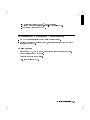
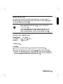
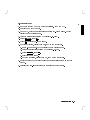
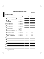
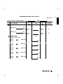
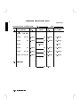
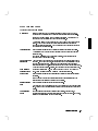
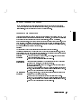
User's Guide
HP 81531A Sensor Module
SERIAL NUMBERS
This manual applies to all instruments.
ABCDE
HP Part No. 81531-90011
Printed in Germany
Second Edition
E0796
Control Serial Number: Edition 2 applies directly to all instruments.
Edition 1 : 1st May 1990 : 81531-90011 : E0590
1st September 1990 : 81531-90011 : E0990
Edition 2 : 1st September 1991 : 81531-90011 : E0991
1st September 1992 : 81531-90011 : E0992
1st December 1994 : 81531-90011 : E1294
1st July 1996: 81531-90011 : E0796
Safety Considerations
Before operation, you should review the instrument and manual, including the
red safety page, for safety markings and instructions. You must follow these to
ensure safe operation and to maintain the instrument in safe condition.
Initial Inspection
Inspect the shipping container for damage. If there is damage to the container
or cushioning, you should keep it until you have checked the contents of the
shipment for completeness and veried the module both mechanically and
electrically.
The Performance Tests give procedures for checking the operation of the
module. If the contents are incomplete, mechanical damage or defect is
apparent, or if a moduke does not pass the operator's checks, notify the nearest
Hewlett-Packard oce.
Warning
To avoid hazardous electrical shock, do not perform
electrical tests when there are signs of shipping damage to
any portion of the outer enclosure (covers, panels, etc.).
Power Requirements
The HP 81531A operates when installed into the HP 8153A Optical Multimeter
mainframe.
Operating Environment
The HP 8153A safety information summarizes the HP 81531A operating
environment ranges. In order for the HP 81531A to meet specications, the
operating environment must be within the limits specied in this section.
Input/Output Signals
iii
Caution
A maximum of 15V can be applied as an external voltage to any
BNC connectors.
Storage and Shipment
The module can be stored or shipped at temperatures between 040 C and
+70 C. The module should be protected from temperature extremes that may
cause condensation within it.
iv
Contents
C. HP 81531A Specications
Supplementary Performance Characteristics . . . . . . . . . . .
Analog output: . . . . . . . . . . . . . . . . . . . . . . .
D. Performance Tests
Introduction . . . . . . . . .
Equipment Required . . . .
Test Record . . . . . . . . .
Test Failure . . . . . . . . .
Instrument Specication . . .
Performance Test . . . . . .
Accuracy and Linearity Test
Test Setup . . . . . . . .
I. Accuracy Test . . . . .
II. Linearity Test . . . . .
III. Noise Test . . . . . . .
.
.
.
.
.
.
.
.
.
.
.
.
.
.
.
.
.
.
.
.
.
.
.
.
.
.
.
.
.
.
.
.
.
.
.
.
.
.
.
.
.
.
.
.
.
.
.
.
.
.
.
.
.
.
.
D-1
D-1
D-2
D-2
D-2
D-3
D-3
D-3
D-4
D-5
D-8
The Cleaning Kit . . . . . . . . . . . . . . . . . . . .
Other Cleaning Tools . . . . . . . . . . . . . . . . .
Preserving Connectors . . . . . . . . . . . . . . . . .
Cleaning Instrument Housings . . . . . . . . . . . . .
Correct Cleaning Procedure . . . . . . . . . . . . . .
Cleaning Cable Connectors . . . . . . . . . . . . . .
Cleaning Connector Adapters . . . . . . . . . . . . .
Cleaning Connector Interfaces . . . . . . . . . . . .
How to clean instruments with a recessed lens interface
Light dirt . . . . . . . . . . . . . . . . . . . . .
Heavy dirt . . . . . . . . . . . . . . . . . . . .
.
.
.
.
.
.
.
.
.
.
.
.
.
.
.
.
.
.
.
.
.
.
.
.
.
.
.
.
.
.
.
.
.
.
.
.
.
.
.
.
.
.
.
.
E-1
E-3
E-4
E-4
E-5
E-5
E-6
E-6
E-7
E-7
E-7
E. Cleaning Procedures
.
.
.
.
.
.
.
.
.
.
.
.
.
.
.
.
.
.
.
.
.
.
.
.
.
.
.
.
.
.
.
.
.
.
.
.
.
.
.
.
.
.
.
.
.
.
.
.
.
.
.
.
.
.
.
.
.
.
.
.
.
.
.
.
.
.
.
.
.
.
.
.
.
.
.
.
.
.
.
.
.
.
.
.
.
.
.
.
.
.
.
.
.
.
.
.
.
.
.
.
.
.
.
.
.
.
.
.
.
.
.
.
.
.
.
.
.
.
.
.
.
.
.
.
.
.
.
.
.
.
.
.
C-3
C-3
Index
Contents-1
Figures
D-1. Accuracy and Linearity Test Setup . . . . . . . . . . . . . .
D-2. Addition of results (example) . . . . . . . . . . . . . . . . .
Contents-2
D-4
D-7
C
C
HP 81531A Specications
Specications describe the instrument's warranted performance. Supplementary
performance characteristics describe the instrument's non-warranted typical
performance.
Because of the modular nature of the instrument, these performance
specications apply only to this module. You should insert these pages into the
appropriate section of the manual.
HP 81531A Specications C-1
C
HP 81531A Specications
Sensor Element
Wavelength range
Power range
Display resolution
In GaAs
800-1700nm
+3 to -90dBm
dBm, dB 0.001
0.0001 on printout
Watt 0.01 to 10
(depending on power range)
Applicable ber type
9/125m - 100/140m, NA0.3
Uncertainty (Accuracy) 62.5% (1000-1650nm)[1]
Total Uncertainty
65%61.5pW (1000-1650nm)[2]
Linearity
(0 to -70dBm)
18 C to 28 C const. temp 60.015dB61pW
0 C to 55 C const. temp 60.05dB61.5pW
Noise
<1.5pW (1200-1600nm)
peak-peak, avg. time 1sec
Dimensions
75mm H, 32mm W, 335mm D (2.8"21.3"213.2")
Weight
net 0.6kg (1.3lbs), shipping 1kg (2.2lbs)
Recalibration period
2 years
Warmup time
20 min.
Information on the traceability of power meters is available on request
[1] at the following reference conditions:
Power level 10W (-20dBm), Continuous Wave (CW).
Fiber 50m graded index, NA=0.2, fully excited.
Ambient temperature 23 C65K.
Connector Diamond HMS-10/HP.
At day of calibration (add 0.3% for aging over one year, add 0.6% over
two years).
Spectral width of source <10nm.
[2] at the following operating conditions:
Fiber 50m, NA 0.2.
For NA >0.2 add 1%.
C-2 HP 81531A Specications
C
Ambient temperature 0 to 55 C, non-condensing.
Within 1 year after calibration, add 0.3% for second year.
For Biconic Connector add 61%.
Supplementary Performance Characteristics
Add 1% to total uncertainty for the full wavelength range.
Outside the specied wavelength range, the noise increases by up to 5 times
the value shown above.
Analog output:
Bandwidth: DC, 300 to 400Hz, depending on range and sensor module.
Output voltage: 0 to 2V into open.
Output impedance: 600
typical.
Max. input voltage: 610V.
HP 81531A Specications C-3
D
Performance Tests
Introduction
The procedures in this section test the performance of the instrument.
The complete specications to which the HP 81531A is tested are given in
Appendix C. All tests can be performed without access to the interior of the
instrument. The test equipment given corresponds to tests carried out with
Diamond HMS-10/HP conectors.
Equipment Required
Equipment required for the performance test is listed in the table below. Any
equipment which satises the critical specications of the equipment given in
the table, may be substituted for the recommended models.
Instrument/Accessory
Recommended Model
Power Meter Standard
HP 8153A Mainframe with
#C01
HP 81533A Optical Head
Interface Module with
HP 81524A Optical Head
Required Characteristics
Uncertainty
61.5%
Multimeter Mainframe
HP 8153A
CW Laser Sources
HP 81552SM and HP 81553SM or Wavelength
HP 81554SM
Uncertainty
61.5nm
Optical Attenuator
HP 8156 Option 101
Connector Adapter (head) HP 81000AA
Connector Interface
HP 81000AI 4ea (08154-61701)
Singlemode Fiber
HP 81101AC 2ea
Plastic Cap
5040-9351 2ea
Performance Tests D-1
D
D
Test Record
Results of the performance test may be tabulated on the Test Record provided
at the end of the test procedures. It is recommended that you ll out the Test
Record and refer to it while doing the test. Since the test limits and setup
information are printed on the Test Record for easy reference, the record can
also be used as an abbreviated test procedure (if you are already familiar with
the test procedures). The Test Record can also be used as a permanent record
and may be reproduced without written permission from Hewlett-Packard.
Test Failure
If the HP81531A fails any performance test, return the instrument to the
nearest Hewlett-Packard Sales/Service Oce for repair.
Instrument Specication
Specications are the performance characteristics of the instrument which
are certied. These specications, listed in Appendix C, are the performance
standards or limits against which the HP 81531A can be tested. Appendix C
also lists some supplemental characteristics of the HP 81531A. Supplemental
characteristics should be considered as additional information.
Any changes in the specications due to manufacturing changes, design, or
traceability to the National Institute of Standards and Technology (NIST), will be
covered in a manual change supplement, or revised manual. Such specications
supercede any that were previously published.
D-2 Performance Tests
Performance Test
D
The performance test given in this section includes the Accuracy Test, the
Linearity Test, and the Noise Test. Perform each step in the order given, using
the corresponding test equipment.
Note
Make sure that all optical connections of the test setups given
in the procedure are dry and clean. DO NOT USE INDEX
MATCHING OIL.
The optical cables from the laser source to and from the HP
8156A Attenuator to the power meter must be xed on the
table to ensure minimum cable movement during the tests.
Accuracy and Linearity Test
Specications
Uncertainty :
Linearity :
HP 81531A
62.8%y (1000-1650nm)
60.015dB61pW
y includes aging.
Test Setup
1. Make sure that cable connector, detectors and adapters are clean.
2. Connect the equipment as shown in Figure D-1. Ensure that the cables to
and from the attenuator are xed on the table and that both the optical head
and the DUT are close together so that minimum cable movement is required
when connecting the cable to the head or to the DUT.
Performance Tests D-3
D
Figure D-1. Accuracy and Linearity Test Setup
3. Turn the instruments on, enable the laser source and allow the instruments
to warm up for at least 20 minutes.
Note
The linearity test must only be performed at either 1300nm or
1550nm. The accuracy test must be performed in the -20dBm
range at 10W at both 1300nm and 1550nm.
I. Accuracy Test
1. On both power meters:
a. Set the calibration factor to zero.
b. Set the wavelength to the wavelength of the laser source.
c. Set the instruments into MEAS mode. Make sure AUTOranging is o and
select the -20dBm range.
d. Set the averaging time to 500ms.
2. Make sure that the HP 8156A output is disabled. ZERO the DUT.
3. Connect the HP 8156A output cable to the standard head and ZERO the
standard meter.
4. Enable the HP 8156A output. Change the HP 8156A attenuation until the
power meter standard displays 10.00W.
5. Connect the attenuator output cable to the DUT. Check the DUT display and
note the result in the test record.
6. Repeat steps 1 to 5 at the second wavelength with the corresponding source.
D-4 Performance Tests
II. Linearity Test
1. Make sure that the HP 8156A output is disabled. ZERO the DUT.
2. Enable the HP 8156A output.
3. On the DUT, switch o autoranging and select the -20dBm range. Set the
display to show results in dBm.
4. Alter the attenuation until the DUT displays -17.4dBm.
5. Press 4Disp!Ref5, then 4dB5.
6. Press 4Up5 to select the -10dBm range.
7. Note the deviation, displayed in dB, as R1 on the test record.
a. In the -10dBm range. Set the display to show results in dBm.
b. Alter the attenuation until the DUT displays -7.4dBm.
c. Press 4Disp!Ref5, then 4dB5.
d. Select the 0dBm range.
e. Note the deviation, displayed in dB, as R2 on the test record.
8. Repeat the steps a to e at all the range and level settings shown in the test
record.
9. Calculate the non-linearity using the formulae in the test record.
Performance Tests D-5
D
Example Results for the Linearity test
D
Test
Minimum
Maximum Measurement
No. Test Description
Spec.
Result
Spec.
Uncertainty
II. Linearity Test
dB
Range Power (dBm)
-20dBm
-17.4
Disp!Ref
-10dBm
0.004 =R1
-10dBm
0dBm
-7.4
Disp!Ref
-20dBm
-30dBm
-27.4
Disp!Ref
-30dBm
-40dBm
-37.4
Disp!Ref
-40dBm
-50dBm
-47.4
Disp!Ref
D-6 Performance Tests
-0.008 =R2
-0.008 =R3
-0.004 =R4
0.02 =R5
Example Calculated Results for the Linearity Test
Test
No. Test Description
Non-Linearity
Range
Minimum
Spec.
Result
Maximum Measurement
Spec.
Uncertainty
Formula
0dBm
R1+R2 -0.015dB -0.004dB +0.015dB
60.006dB
-10dBm
R1 -0.015dB 0.004dB +0.015dB
60.006dB
-20dBm
60.00dB
0.000dB
-30dBm
R3 -0.015dB -0.008dB +0.015dB
60.006dB
-40dBm
R3+R4 -0.015dB -0.012dB +0.015dB
60.008dB
-50dBm R3+R4+R5 -0.015dB 0.008dB +0.015dB
60.010dB
Shown graphically, these results look as shown in the following gure:
Figure D-2. Addition of results (example)
Performance Tests D-7
D
D
III. Noise Test
Note
The noise measurement must be performed with either a
module or a blank panel in the second channel position.
Connect the equipment as shown in Figure D-1.
Disable the HP 8156A output.
On the DUT, select AUTOranging, and display in Watts. Set the averaging time
to 1s.
Press 4Zero5.
Select the MENU mode.
Press 4Record5, to select Stability.
Press 4Edit5 and select the T_TOTAL parameter. Set T_TOTAL to 1 minute.
Press 4Edit5, and then 4Exec5 to run the noise measurement.
When the test has completed, press 4More5 to select the SHOW application. Press
4Edit5 and then 4Next5/4Prev5 to display the DIFF result.
Note the DIFF result as the noise value in the test record.
D-8 Performance Tests
Performance Test for the HP 81531A
Page 1 of 4
Test Facility:
Report No.
Date
Customer
Tested By
Model
HP81531A Sensor Module
Serial No.
Ambient temperature
C
Options
Relative humidity
%
Firmware Rev.
Line frequency
Hz
Special Notes:
Performance Tests D-9
D
Performance Test for the HP 81531A
D
Page 2 of 4
Test Equipment Used:
Description
Model No.
1. Lightwave Multimeter (Std.)
HP 8153A
2. Opt. Head Interface Module
HP 81533A
3. Optical Head
HP 81524A
4a1. CW Laser Source
HP 81552SM
4a2. CW Laser Source
HP 81553SM
4b. CW Laser Source
HP 81554SM
5. Optical Attenuator
Trace No.
Cal. Due Date
6. Lightwave Multimeter (DUT)
HP 8156A
Opt.101
HP 8153A
7. Connector Interface
HP 81000AI
N/A
N/A
8. Connector Adapter
HP 81000AA
N/A
N/A
9. Singlemode Fiber (2ea)
HP 81101AC
N/A
N/A
12.
13.
14.
15.
16.
17.
18.
D-10 Performance Tests
Performance Test for the HP 81531A
Model HP 81531A Sensor Module
Test
No. Test Description
I. Accuracy Test
No.
Minimum
Spec.
Date
Result
W
Page 3 of 4
Maximum Measurement
Spec.
Uncertainty
measured at
nm
Output Power 9.72W
10.28W
62%
measured at
nm
Output Power 9.72W
10.28W
62%
II. Linearity Test
Range Power (dBm)
-20dBm
-17.4
Disp!Ref
-10dBm
-10dBm
0dBm
-7.4
Disp!Ref
-20dBm
-30dBm
-27.4
Disp!Ref
-30dBm
-40dBm
-37.4
Disp!Ref
-40dBm
-50dBm
-47.4
Disp!Ref
dB
=R1
=R2
=R3
=R4
=R5
Performance Tests D-11
D
Performance Test for the HP 81531A
D
Model HP 81531A Sensor Module
No.
Test
Minimum
No. Test Description
Spec.
Result
Non-Linearity
Range
Page 4 of 4
Date
Maximum Measurement
Spec.
Uncertainty
Formula
0dBm
R1+R2 -0.015dB
dB +0.015dB
60.006dB
-10dBm
R1 -0.015dB
dB +0.015dB
60.006dB
-20dBm
0.000dB
0.00dB
-30dBm
R3 -0.015dB
dB +0.015dB
60.006dB
-40dBm
R3+R4 -0.015dB
dB +0.015dB
60.008dB
-50dBm R3+R4+R5 -0.015dB
dB +0.015dB
60.010dB
III. Noise Test
pW <1.5pW
D-12 Performance Tests
E
Cleaning Procedures
E
The Cleaning Kit
A full cleaning kit contains the following items:
Isopropyl alcohol This is usually available from pharmaceutical suppliers or chemists.
If possible, use alcohol supplied for medical purposes, rather than impure
alcohol or alcohol with additives.
Caution
Do not use other solvents as some can damage plastic materials and claddings.
For example, Acetone dissolves the adhesives used in ber optic devices.
Warning
Never drink this alcohol as this can lead to blindness or other serious damage
to your health.
Cotton-swabs
Use swabs such as Q-tips or other cotton-swabs. These are typically available
from local distributors of medical or hygiene products (such as supermarkets or
pharmacies).
Note If you are cleaning connector interfaces or adapters, the diameter of the
cotton swab is important. Cotton swabs for babies normally have a smaller
diameter.
Caution
Do not use foam swabs, as these can leave lmy deposits on the surface you
are cleaning.
Store your cotton-swabs carefully and never reuse them. Dust and dirt from
the air or from previous cleaning, can scratch or dirty your optical device.
Soft-tissues
These are available from most stores and distributors of medical and hygiene
products (such as supermarkets or pharmacies).
Use multi-layer tissues made from non-recycled cellulose. These are more
absorbent and softer than other types and they do not scratch the surface of
your device.
Caution
Store your soft-tissues carefully and never reuse them, as dust and dirt from
the air or from previous cleaning can scratch and dirty your optical device.
Cleaning Procedures E-1
Pipe-cleaner
E
Compressed Air
This is available from tobacco shops.
Ensure that the bristles of the pipe-cleaner are soft, so that they do not scratch
your device during cleaning.
Caution
Store your pipe-cleaners carefully and never reuse them as dust and dirt from
the air or from previous cleaning can scratch and dirty your optical device.
This is available from laboratory suppliers.
It is essential that your compressed air is free of dust, water and oil. Only use
clean, dry air. If you do not, it can lead to lmy deposits or scratches.
When using compressed air from a can,
Hold the can upright. A slant can cause propellant to escape with the
compressed air and dirty your optical device.
Spray the rst couple of seconds into the air, as the rst stream of
compressed air can contain condensation or propellant. Any condensation
produces a lmy deposit.
If you are using compressed air from a can, you should select one with a
CFC-free propellant, for the sake of the environment.
E-2 Cleaning Procedures
Other Cleaning Tools
To examine devices you also require:
Microscope
Select a microscope with a magnication range of between 50X and 300X.
These should be available from photographic stores or laboratory suppliers.
Ensure that the light source of the microscope is exible. This helps you to
examine your device closely and from dierent angles.
A microscope allows you to determine the type of dirt on your device and its
extent. Then you can choose the correct cleaning procedure and later to
examine the results of cleaning. With a microscope you can also determine if
your optical device is scratched.
Ultrasonic bath This is typically available from photographic stores or laboratory suppliers.
An ultrasonic bath very gently removes greasy and other stubborn dirt from
optical devices.
Only use an ultrasonic bath with isopropyl alcohol, as other solvents can
damage or dirty your optical device.
Warm water and Use water only if you are sure that your optical device will not corrode or be
liquid soap
damaged. Do not use hot water, as this can lead to mechanical stress that can
damage your optical device. Ensure that your liquid soap has no abrasive
properties or perfume in it, as these can scratch or damage your optical device.
Do not use normal washing-up liquid, as it can leave behind an iridescent lm.
Premoistened
These are available from HP. The part number is HP 92193N (80 Wipes per
cleaning wipes box). These are tissues that are moistened with isopropyl alcohol.
Polymer lm
This is typically available from professional photographic stores or laboratory
suppliers.
Polymer lm is very gentle on optical surfaces and is particularly good for
cleaning extremely sensitive devices such as mirrors.
Infrared sensor This is typically available from laboratory suppliers.
card
With this card you can qualitatively check the uniformity of your emitted laser
light, because when the laser light is projected onto the sensor card it becomes
visible.
Some lens cleaning papers and cleaning kits available, for example, in
Lens Cleaning
photographic stores are not suitable for cleaning ber optic devices. To be sure,
Paper
please ask the salesperson or the manufacturer.
Cleaning Procedures E-3
E
Preserving Connectors
E
Listed below are some hints on how to keep your connectors in the best possible condition.
Making
Before you make any connection you must ensure that all cables and
Connections
connectors are clean. If they are dirty, use the appropriate cleaning procedure.
When inserting the ferrule of a patchcord into a connector or an adapter, make
sure that the ber end does not touch the outside of the mating connector or
adapter. Otherwise you will rub the ber end against an unsuitable surface,
producing scratches and dirt deposits on the surface of your ber.
Dust Caps and
Be careful when replacing dust caps after use. Do not press the bottom of the
cap onto the ber as any dust in the cap can scratch or dirty your ber surface.
Shutter Caps
When you have nished cleaning, put the dust cap back on, or close the
shutter cap if the equipment is not going to be used immediately.
Keep the caps on the equipment always when it is not in use.
All of Hewlett-Packard's lightwave instruments and accessories are shipped
with either laser shutter caps or dust caps. If you need additional or
replacement dust caps, contact your Hewlett-Packard sales oce.
Immersion Oil
Where it is possible, do not use immersion oil or other index matching
and Other Index compounds with your device. They are liable to impair and dirty the surface of
the device. In addition, the characteristics of your device can be changed and
Matching
your measurement results aected.
Compounds
Cleaning Instrument Housings
Use a dry and very soft cotton tissue to clean the instrument housing and the keypad. Do not
open the instruments as there is a danger of electric shock, or electrostatic discharge. Opening the
instrument can cause damage to sensitive components, and in addition your warranty will be
voided.
E-4 Cleaning Procedures
Correct Cleaning Procedure
If you are unsure about the correct cleaning procedure for your device or if you are unsure
whether the procedure given here is suitable for your device, check with the manufacturer or
sales distributor, or try the procedure on a dummy or test device rst.
E
Cleaning Cable Connectors
Cleaning connectors is dicult as the core diameter of a singlemode ber is only about 9m. This
generally means you cannot see streaks or scratches on the surface. To be certain of the condition
of the surface of your connector and to check it after cleaning, you need a microscope.
In the case of scratches, or of dust that has been burnt onto the surface of the connector, you may
have no option but to polish the connector. This depends on the degree of dirtiness, or the depth
of the scratches. This is a dicult procedure and should only be performed by skilled personnel,
and as a last resort as it wears out your connector.
Warning
Never look into the end of an optical cable that is connected to an active source.
To assess the projection of the emitted light beam you can use an infrared sensor card. Hold the
card approximately 5 cm from the output of the connector. The invisible emitted light is projected
onto the card and becomes visible as a small circular spot.
Preferred
1. Clean the connector by rubbing a new, dry cotton-swab over the surface
Procedure
using a small circular movement.
2. Blow away any remaining lint with compressed air.
Procedure for
Use this procedure particularly when there is greasy dirt on the connector:
Stubborn Dirt
1. Moisten a new cotton-swab with isopropyl alcohol.
2. Clean the connector by rubbing the cotton-swab over the surface using a
small circular movement.
3. Take a new, dry soft-tissue and remove the alcohol, dissolved sediment and
dust, by rubbing gently over the surface using a small circular movement.
4. Blow away any remaining lint with compressed air.
An Alternative The better, more gentle, but more expensive cleaning procedure is to use an
Procedure
ultrasonic bath with isopropyl alcohol.
1. Hold the tip of the connector in the bath for at least three minutes.
2. Take a new, dry soft-tissue and remove the alcohol, dissolved sediment and
dust, by rubbing gently over the surface using a small circular movement.
3. Blow away any remaining lint with compressed air.
Cleaning Procedures E-5
Cleaning Connector Adapters
E
Caution
Some adapters have an anti-reection coating on the back to reduce back reection. This coating
is extremely sensitive to solvents and mechanical abrasion. Extra care is needed when cleaning
these adapters.
Preferred
1. Clean the adapter by rubbing a new, dry cotton-swab over the surface using
a small circular movement.
Procedure
2. Blow away any remaining lint with compressed air.
Procedure for
Stubborn Dirt
Use this procedure particularly when there is greasy dirt on the adapter:
1. Moisten a new cotton-swab with isopropyl alcohol.
2. Clean the adapter by rubbing the cotton-swab over the surface using a small
circular movement.
3. Take a new, dry soft-tissue and remove the alcohol, dissolved sediment and
dust, by rubbing gently over the surface using a small circular movement.
4. Blow away any remaining lint with compressed air.
Cleaning Connector Interfaces
Caution
Be careful when using pipe-cleaners, as the core and the bristles of the pipe-cleaner are hard
and can damage the interface.
Do not use pipe-cleaners on optical head adapters, as the hard core of normal pipe cleaners can
damage the bottom of an adapter.
Preferred
1. Clean the interface by pushing and pulling a new, dry pipe-cleaner into the
Procedure
opening. Rotate the pipe-cleaner slowly as you do this.
2. Then clean the interface by rubbing a new, dry cotton-swab over the
surface using a small circular movement.
3. Blow away any remaining lint with compressed air.
Procedure for
Use this procedure particularly when there is greasy dirt on the interface:
Stubborn Dirt
1. Moisten a new pipe-cleaner with isopropyl alcohol.
2. Clean the interface by pushing and pulling the pipe-cleaner into the
opening. Rotate the pipe-cleaner slowly as you do this.
3. Moisten a new cotton-swab with isopropyl alcohol.
4. Clean the interface by rubbing the cotton-swab over the surface using a
small circular movement.
5. Using a new, dry pipe-cleaner, and a new, dry cotton-swab remove the
alcohol, any dissolved sediment and dust.
6. Blow away any remaining lint with compressed air.
E-6 Cleaning Procedures
How to clean instruments with a recessed lens interface
Light dirt
If you nd any particles of dirt on the xed connector interface, or on the input
of the optical block, clean them with compressed air.
This cleaning method is gentle to your optical device and is an ideal approach if
there is no fat on the surface of your device.
Heavy dirt
Using compressed air, blow away larger particles of dirt. Clean the recessed lens
interface with a dry cotton swab by rubbing gently over its surface. Then blow
away any remaining laments left by the swab.
Isopropyl alcohol should only be used if there is fat on the lens. In this case,
choose a new swab and moisten it with alcohol. Remove the dirt by gently
rotating the swab using light pressure. Then select a fresh, dry swab to wipe
away the alcohol. Blow away any remaining lament with compressed air.
Caution
Do not press the swabs too hard onto the optical surface of your
device, as this may produce scratches and your recessed lens
could be misaligned.
Alcohol will dissolve some types of dirt. If this then forms a
deposit on the edge of the optical input it cannot be removed.
You should therefore only use alcohol if absolutely necessary.
Other solvents, like Acetone, should also not be used, as they
may damage your optical device and reduce its performance.
Cleaning Procedures E-7
E