1
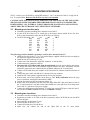
V1
Service Manual
(07/98)
Doremi Labs, Inc.
3631 Cahuenga Blvd. West, Los Angeles, California 90068, U.S.A.
2
TABLE OF CONTENTS
TABLE OF CONTENTS..................................................................................................................................... 2
WARNING........................................................................................................................................................... 3
WARNING........................................................................................................................................................... 3
AVIS ..................................................................................................................................................................... 3
PROTECTING YOURSELF AND THE V1....................................................................................................... 3
CE NOTICE......................................................................................................................................................... 5
1
2
3
4
5
6
7
REPLACING THE POWER SUPPLY ................................................................................................................. 6
1.1 Description:......................................................................................................................................... 6
1.2 Removal Procedure: ............................................................................................................................ 6
1.3 Installation procedure: ........................................................................................................................ 6
REPLACING THE POWER SWITCH ................................................................................................................ 7
MOUNTING SCSI DRIVES .................................................................................................................... 8
3.1 Mounting one Jaz drive only................................................................................................................ 8
3.2 Mounting two Jaz drives ...................................................................................................................... 8
3.3 Mounting one Kingston Data-Express removable drive system ............................................................ 9
3.4 Mounting two Kingston Data-Express removable drive systems ......................................................... 10
3.5 Mounting one Jaz and one Kingston Data-Express removable system................................................ 10
3.6 Setup of the Fast SCSI Seagate Barracuda4 hard drive ST15150N .................................................... 10
3.7 Setup of the Micropolis 3243av 4 GB hard drive. .............................................................................. 11
3.8 Setup of the Seagate Ultra SCSI hard drives 4 GB, 9 GB & 18 GB .................................................... 12
3.9 Setup of the Magneto-Optical Drive (MOD) NIKON BELUGA DD53................................................ 12
3.10 Setup of hard drives other than Seagate Ultra SCSI models ............................................................... 13
3.11 Notes on JAZ cartridges .................................................................................................................... 13
REPLACING THE V1 MAIN BOARD ............................................................................................................. 14
4.1 Removing the V1 Main Board ............................................................................................................ 14
4.2 Installing the V1 Main Board............................................................................................................. 14
4.3 Replacing the Flash EPROM on the V1 Main Board.......................................................................... 15
REPLACING THE V1 REMOTE CONTROL BOARD ........................................................................................ 16
5.1 Replacing the RCV1 board ................................................................................................................ 16
5.2 Replacing the EPROM on the RCV1 board........................................................................................ 16
ADJUSTING STICKY CAPS ON THE V1 REMOTE CONTROL .......................................................................... 17
INSTRUCTIONS FOR INITIAL SETUP & TRANSPORT..................................................................... 18
3
WARNING
THIS APPARATUS MUST BE EARTHED
IMPORTANT
WARNING
Power requirements for electrical equipment vary from area to area. Please ensure that your V1 meets the
power requirements in your area. If in doubt, consult a qualified electrician or Doremi Labs, Inc. dealer.
120VAC
220-230/240VAC
240VAC
@60Hz for USA and CANADA rating 1A
@50Hz for Europe rating 0.5A
@50Hz for Australia rating 0.5A
AVIS
Le voltage peut differer d’un pays a l’autre. Il faut que le V1 soit ajuste au voltage du pays.
LA SOURCE DE PUISSANCE DOIT AVOIR UN CONDUCTEUR CONNECTE A LA TERRE.
Toutes reparations doient etre effectuees par une personne qualifiee.
AFIN D’EVITER UN CHOC ELECTRIQUE, VEUILLEZ NE PAS ENLEVER LE CAPOT.
PROTECTING YOURSELF AND THE V1
Never touch the AC plug with wet hands
Always disconnect the V1 from the power supply by pulling on the plug, not the cord.
Allow only a Doremi Labs, Inc. dealer or qualified professional engineer to repair or reassemble the V1.
Apart from voiding the warranty, unauthorized engineers might touch live internal parts and receive a
serious electric shock
Do not put, or allow anyone to put any object, especially metal objects into the V1
Use only an AC power supply. Never use a DC power supply.
If water or any other liquid is spilled into or onto the V1, disconnect the power, and call your dealer.
Make sure the unit is well ventilated, and away from direct sunlight.
To avoid damage to internal circuitry, as well as the external finish, keep the V1 away from sources of
direct heat (stoves, radiators, etc.).
Avoid using aerosol insecticides, etc. near the V1. They may damage the surface, and may ignite.
Do not use denatured alcohol, thinner or similar chemicals to clean the DR8. They will damage the finish.
Modification of this equipment is dangerous, and can result in the functions of the V1 being impaired.
Never attempt to modify the equipment in any way.
In order to ensure optimum performance of your V1, select the setup location carefully, and make sure the
equipment is used properly. Avoid setting up the V1 in the following locations:
1. In a humid or dusty environment
2. In a room with poor ventilation
3. On a surface which is not horizontal
4. Inside a vehicle such as a car, where it will be subject to vibration
5. In an extremely hot or cold environment
4
WARNING!!
To prevent fire or shock hazard, do not expose this appliance to rain or moisture
CAUTION
RISK OF ELECTRIC SHOCK
DO NOT OPEN
CAUTION:
!
TO REDUCE THE RISK OF ELECTRIC SHOCK,
DO NOT REMOVE COVER (OR BACK).
NO USER-SERVICEABLE PARTS INSIDE.
REFER SERVICING TO QUALIFIED SERVICE PERSONNEL.
The lightning flash with the arrowhead symbol superimposed
across a graphical representation of a person, within an equilateral
triangle, is intended to alert the user to the presence of uninsulated
“dangerous voltage” within the product’s enclosure; that may be
of sufficient magnitude to constitute a risk of electric shock.
!
The exclamation point within an equilateral triangle is intended to
alert the user to the presence of important operating and
maintenance (servicing) instructions in the literature
accompanying the appliance.
5
CE NOTICE
Marking by the symbol
indicates compliance of the device to the EMC (Electromagnetic Compatibility)
directive and to the Low Voltage directive of the European Community. Such marking is indicative that this
device meets or exceeds the following technical standard:
• EN 55022 "Limits and Methods of Measurement of Radio Interface Characteristics of Information
Technology Equipment."
A "Declaration of Conformity" in accordance with the above standard has been made and is on file at
Doremi Labs, Europe, Valbonne, France.
6
1 Replacing the Power Supply
1.1
Description:
The Power supply used is a standard PC power supplies with special connectors
mounted at Doremi Labs. It is best that you get the replacement from Doremi so it will
have all the right connectors.
1.2
Removal Procedure:
♦
♦
♦
♦
♦
♦
♦
♦
1.3
Disconnect all cables including power from the back of the V1.
Remove the top cover of the V1.
Unplug all power connectors from the V1 main board and drives.
Remove the power switch, see Replacing the Power Switch below for more details.
Remove the 4 screws holding the power supply to the back of the unit.
Remove the 2 nuts holding the power supply to the internal bracket.
Remove the 2 nuts holding the power supply bracket to the chassis.
Remove the power supply and bracket all together.
Installation procedure:
♦
♦
♦
♦
♦
♦
Install the bracket and the power supply in place.
Install the 4 screws holding the power supply to the back of the V1.
Install the 2 nuts holding the bracket to the chassis.
Install the 2 nuts holding the power supply to the bracket.
Install the power switch, see Replacing the Power Switch below for more details.
Plug the power cables back on the V1 main board and drives. The cable with 2 red and 2 black
colors goes on J14 and the cable with 2 black, one blue and one yellow cable goes on J19.
Severe damage to the board might occur if these two cables are interchanged.
CAUTION NOTE: FOR VENTILATION PURPOSES, THE OPENEING OF THE TOP COVER
SHOULD ALWAYS BE TOWARDS THE HARD DISK TRAYS AND NOT TOWARDS THE
POWER SUPPLY. ALL INTERNAL CABLES SHOULD BE PLACED AT LEAST ONE INCH
ABOVE THE CIRCUIT BOARD, USE CABLE TIES IF NECESSARY.
7
2 Replacing the Power Switch
♦
♦
♦
♦
♦
Disconnect the power connector from the back of the V1 very important.
Pull out the power switch from the front.
Mark the direction of the switch (O to the right) and mark the colors of the wires.
Remove all four connectors after marking the way they were connected.
Install the four connectors on the new power switch:
-Black and brown horizontally aligned.
-Blue and white horizontally aligned.
CAUTION NOTE: FOR VENTILATION PURPOSES, THE OPENEING OF THE TOP COVER
SHOULD ALWAYS BE TOWARDS THE HARD DISK TRAYS AND NOT TOWARDS THE
POWER SUPPLY. ALL INTERNAL CABLES SHOULD BE PLACED AT LEAST ONE INCH
ABOVE THE CIRCUIT BOARD, USE CABLE TIES IF NECESSARY.
3
8
MOUNTING SCSI DRIVES
The V1 is factory set to SCSI ID6 by setting DIP switches 1, 2 & 3 on the back of the V1 to high, low &
low. To avoid conflicts, Don't use this ID 6 for any drive to be installed.
CAUTION NOTE: FOR VENTILATION PURPOSES, THE OPENEING OF THE TOP COVER
SHOULD ALWAYS BE TOWARDS THE HARD DISK TRAYS AND NOT TOWARDS THE
POWER SUPPLY. ALL INTERNAL CABLES SHOULD BE PLACED AT LEAST ONE INCH
ABOVE THE CIRCUIT BOARD, USE CABLE TIES IF NECESSARY.
3.1
Mounting one Jaz drive only
♦
♦
♦
Disconnect all cables including power from the back of the V1.
Set the SCSI ID of the Jaz to 4, usually this is the Iomega factory default for the Jaz drive.
Refer to the Jaz manual to make sure the SCSI ID is set correctly.
Jaz SCSI ID setting: A2
A1
A0
ID #
OFF
OFF
OFF
0
OFF
OFF
ON
1
OFF
ON
OFF
2
OFF
ON
ON
3
ON
OFF
OFF
4
ON
OFF
ON
5
ON
ON
OFF
6
ON
ON
ON
7
The following procedure should be repeated for each Jaz drive mounted on the V1:
♦ Install the Jaz drive in the 3 1/2 to 5 1/4 bracket adapter supplied with the Jaz drive according to
the instruction supplied with the Jaz drive.
♦ Install the Jaz drive on the top V1 tray.
♦ Connect one of the internal free 50pin IDC connector to the Jaz Drive.
♦ Connect the power connector to the Jaz.
♦ Disconnect the SCSI ribbon cable from the main board (near the power supply) and connect
the end of this cable to the SCSI terminator supplied with the Jaz drive. This means that the
50pin IDC connector is now connected to the terminator and not to the V1 main board.
♦ Connect a SCSI cable from your computer to the Centronics 50 connector located on the back of
the V1.
♦ Connect the power cable, turn ON the V1 then turn ON your computer.
♦ Install the Jaz Tools software supplied with the Jaz on your computer
♦ Run Jaz tools, select Drive Options, set the drive to “No” Write verification and set the sleep
time to 30 minutes, then hit the button labeled “SET”.
♦ Quit the Jaz tools, turn OFF the computer and the V1.
♦ Remove the SCSI terminator from the end of the 50pin ribbon IDC cable and connect it back to
the V1 main board pin 1 (red mark on the cable) should be to your right if you are looking at the
front of the V1 (pin closer to the power supply).
♦ Connect the termination supplied with the V1 on the rear external SCSI port, switch ON the V1
and execute a Format command followed by an Initialize command.
3.2
Mounting two Jaz drives
♦
♦
♦
♦
♦
♦
Disconnect all cables including power from the back of the V1.
Repeat the procedure A. for each of the drives separately, and use SCSI ID4 for one and SCSI
ID3 for the other.
Mount Jaz ID3 on the bottom V1 tray.
Mount Jaz ID4 on the top V1 tray.
Connect SCSI and power to both drives.
Make sure you connect the end of the 50pin IDC to the V1 main board.
9
3.3
Mounting one Kingston Data-Express removable drive system
♦
♦
Disconnect all cables including power from the back of the V1
Prepare your Kingston receiver according to one of the following diagrams:
♦
Install the hard driveterminator
in the resistors
carrier (See Sections 0, 0, 0 for setup), connect the SCSI Id cable
(SIP) use this jumper
supplied (black/brown/red)
setting to the correct jumpers onAthe Bhard drive (Check also the direction).
Install the receiver on the bottom V1 tray.
Connect SCSI and power to the Data-Express.
50 PIN SCSI CONNECTOR
Power ON the V1 and set the SCSI ID of the Data-Express to ID3 (screw on the right hand side
of the receiver) using the screwdriver provided with the Data-Express. For more detail refer to
the Data-Express manual. J4
Execute
a
Format
command
followed
by View an
Initialize
command.
Rear
of the
♦
♦
♦
♦
If you dont see 3
W3
W1
W2
J6
J6A
Kingston Receiver
If y ou see 3 terminator resistors
(SIP) rem ove them and use this
jum per setting
W1
W2
J6
B
A
50 PIN SCSI CONNECTOR
J4
J7
Rear View of the
Kingston Receiver
J3
J6
68 PIN SCSI CONNECTOR
J2
J4
W2
W1
J6A
10
3.4
Mounting two Kingston Data-Express removable drive systems
♦
3.5
Repeat the procedure C. for both frames. Set the bottom tray to ID3 and the top one to ID 4.
Mounting one Jaz and one Kingston Data-Express removable system
♦
♦
Repeat procedure A. for the Jaz, set it to ID4 and install it on the top V1 tray.
Repeat procedure C. for the Data-Express, set it to ID3 and install it on the bottom V1 tray.
3.6 Setup of the Fast SCSI Seagate Barracuda4 hard drive ST15150N
(Obsolete drive)
These are the two connectors that should be configured on the ST15150N:
PIN 1
J01
TP FROM BUS
This is the only
jumper that
should be
installed on J01
BLK
Red, Brown & Black
wires on LEFT
BRN
J4
RED
To Data-Express
POWER
CONNECTOR
Rear View
J01 should only have one jumper to set the termination power from SCSI bus. That position is marked in
the drawing above.
The Data-Express carrier should be connected to the drive with 3 cables:
1. Power Cable
2. SCSI Cable
3. SCSI ID number cable: this cable is supplied by Kingston with the Data-Express and has one 3 pin
connector that connects to the Data-Express carrier, and three 2 pin connectors that should be
connected to the drive. Note that each of those 3 wires are connected to only one side of the 2 pin
connector, that side with the wire should be connected to the left row of J4 if you are looking straight to
the back of the drive.
Extra care should be given as to not have cable number 3 described above be caught between the drive and
the Data-Express carrier chassis.
11
3.7
Setup of the Micropolis 3243av 4 GB hard drive.
These are the two connectors that should be configured on the 3243av:
POWER and SCSI
CONNECTORS
To Data-Express
W2
B
L
K
B
R
N
R
E
D
Red, Brown & Black
wires on the bottom
Rear View of the drive in the mounting position
TP FROM BUS
This is the only
jumper that
should be
installed on W2
Bottom View of the drive
W2 should only have one jumper to set the termination power from SCSI bus. That position is marked in
the drawing above.
Remove the two terminator resistors RN1 and RN2 (10 pin SIP resistor)
The Data-Express carrier should be connected to the drive with 3 cables:
1. Power Cable
2. SCSI Cable
3. SCSI ID number cable: this cable is supplied by Kingston with the Data-Express and has one 3 pin
connector that connects to the Data-Express carrier, and three 2 pin connectors that should be
connected to the drive. Note that each of those 3 wires are connected to only one side of the 2 pin
connector, that side with the wire should be connected to the bottom row of the DIP connector if you
are looking straight to the front of the drive.
Extra care should be given as to not have cable number 3 described above be caught between the drive and
the Data-Express carrier chassis.
3.8
12
Setup of the Seagate Ultra SCSI hard drives 4 GB, 9 GB & 18 GB
Seagate has 2 series of Ultra SCSI drives: Barracuda and Cheetah.
Seagate part Numbers
Narrow SCSI
Barracuda4LP
ST34371N
ST34572N
ST34573N
ST34371W
ST34572W
ST34573W/LW
Wide SCSI
Seagate part Numbers
Narrow SCSI
Wide SCSI
Cheetah4LP
ST34501N
ST34501W
ST34502LW
Barracuda9
ST19171N
Barracuda9LP
ST39173N
Barracuda18
ST118273N
ST19171W
ST39173W
ST39173LW
ST118273W
ST118273LW
Cheetah9
ST19101N
ST19101W
Cheetah9LP
Cheetah18
ST39102LW
ST118202LW
These are the two connectors that should be configured for all these drives:
To
Da
ta
Ex
pr
es
s
BLK
4
BRN
RED
8
1
Pin
1
Pin
ORANGE
J2 shouldSCSIhave
a jumper
power from SCSI bus (see above drawing). For LW drives,
CONNECTOR
(REAR) to set the termination
SCSI CONNECTOR (REAR)
the Force Single Ended Jumper, must also be installed.
BLK
HDA
BRN
RED
DELAY MOTOR START
To
Da
ta
Ex
pr
es
s
1
2
DELAY MOTOR START
TP FROM BUS
TP FROM BUS
The Data-Express carrier should be connected to the drive with 3 cables:
TP TO BUS
TP TO BUS
1. Power
Cable
2. TPSCSI
Cable
FROM DRIVE
TP FROM DRIVE
3. SCSI
ID
number
cable:
this
cable is supplied by Kingston with the Data-Express and has one 3 pin
RESERVED
RESERVED
J5
connector (5 for wide) that connects to the Data-Express
carrier, and
three (five for wide) 2 pin
ADDR
PARITY DISABELED
DISABELED
connectors that should bePARITY
connected
to the drive. NoteREAR
that
those
3 CONNECTOR)
wires is connected to only
VIEWeach
FOR WIDEof
(NEXT
TO THE SCSI
onePROTECT
side of the 2 pin connector.
That side with the wire should be connected to the top row of J6 (J5 for
WRITE
WRITE PROTECT
wide) if you are looking straight
at the front of the drive (back of the drive for wide). On the wide
MOTOR START EN
MOTOR START EN
drives the yellow cable should not be connected to anything.
Extra
careENDED
should be given as to
not
have cable number 3 described above be caught between the drive and
FORCE SINGLE
TERM
ENABLE
the Data-Express carrier chassis.
J2
1
2
♦
4
♦
Setup of
the Magneto-Optical
NIKON BELUGA DD53
FRONT
FRONTDrive (MOD)
J6
RES
3.9
J2
All Other drives
Listed above
RES
ST34573LW
ST34502LW
ST39173LW
ST39102LW
ST118273LW
ST118202LW
ADDR
VIEW
FRONT VIEW FOR
(OTHER SIDE
FROM THE:SCSI CONNECTOR)
The top DIP switch mustBOTTOM
be configured
according
toNARROW
the table
below
Switch -1 ON (Default)
Switch -2 ON Disable SCSI Termination
Switch -3 OFF Disable Read after Write
Switch -4 ON (Default)
Switch -5 ON (Default)
Switch -6 ON (Default)
Switch -7 ON Direct Access Device (Very important)
Switch -8 OFF (Default)
The 2.6 GB cartridge must be 1024 Bytes/sectors
BOTTOM VIEW
13
3.10 Setup of hard drives other than Seagate Ultra SCSI models
♦
Generally speaking, the basic setup must be as following :
♦
♦
♦
♦
♦
Drive Termination Disable
Termination Power from the SCSI bus
Parity Enabled
Write Protect (if any) Disabled
Others jumpers or switches : default position should be OK
In order to get the best performance in video/audio recording DOREMI Labs has selected the Seagate
Ultra SCSI family because these drives offer the best performance currently available on the SCSI-2 bus
and are validated to support 4:1 compression with a single drive and the audio only insert capabilities.
Operation and performance with drives from other sources (Micropolis, IBM, Fujitsu...) must be checked
on the V1 by the user; DOREMI LABS in this case cannot guarantee the full operation or performance. In
case of technical problems, please inform DOREMI Labs with a full description of what has been noticed.
3.11 Notes on JAZ cartridges
Some precautions need to be followed with the JAZ cartridges :
♦ Eject them before any transportation or before switching off the V1
♦ Don't use them in case of condensing (Humidity going into water drops), this may produce error while
record or play !
In case of bad sectors on cartridges, you can test them with Win95 Surface Scan or any low level utility
software like FWB Hammer for Mac.
14
4 Replacing the V1 main board
All PC boards are very sensitive to ESD. Make sure you touch the V1 power supply before
any direct contact with the PC boards.
The V1 main board is also refered to as DVP100.
4.1
Removing the V1 Main Board
♦
♦
♦
♦
♦
♦
♦
♦
♦
4.2
Remove all cables from the back of the V1.
Remove the V1 top cover.
Remove the (4) screws from the S-VIDEO connectors.
Remove the (4) screws from the MIDI connectors.
Remove the (4) screws from the XLR connectors.
Remove the (4) nuts from the BNC connectors.
Remove the 7 screws holding the V1 main board to the chassis. Do not remove the power
supply. Write down the positions of those screws becuase they differ for each revision of the
main board.
A Data-Express mounted on the V1 bracket should be removed to allow space for the main
board to go out. A Jaz drive can stay.
Remove the old main board.
Installing the V1 Main Board
If the new board has a sticker blocking one or more of the holes, make sure it stays there
♦
♦
♦
♦
♦
♦
♦
♦
♦
♦
the
♦
If the new board is rev D or higher, remove the two nuts located on the DB9 connector J5.
If the new board is revC or lower make sure the nuts are screwed to the DB9 connector J9.
Install the new main board in place.
Install the 7 screws that hold the main board to the chassis.
Install all the screws and nuts on the back of the V1.
Connect the 10 pin IDC connector to J6. Pin 1 (red mark on the cable) should be to the left if
looking at the front of the V1.
Connect the 16pin IDC audio cable to J26. Pin 1 (red mark on the cable) should be to the right if
looking at the front of the V1.
Connect the SCSI 50 pin IDC cable to J9. Pin 1 (red mark on the cable) should be to the right if
looking at the front of the V1.
The IDC cable connection is very sensitive. Any wrong connection will cause severe damages to
the RCV-PCB board.
If by mistake, the cables from the remote control board (RCV-PCB) were unplugged, they
should be connected back as follows:
-IDC10 cable to the IDC10 connector. Pin 1 (red mark on the cable) should be to your
right if you are looking at the front of the V1
-IDC16 cable to IDC16 connector. Pin 1 (red mark on the cable) should be towards
top of the V1.
Install all the screws on the back of the V1 .
15
4.3
Replacing the Flash EPROM on the V1 Main Board
To replace the Flash EPROM on the RCV1 board:
♦
♦
♦
♦
♦
Remove all cables from the back of the V1.
Remove the V1 top cover.
Locate the socketed 32 pin PLCC IC (U6: NH29EE010) on the DVP100 PC board, note the
direction of pin 1 (cut on one corner of the socket) and remove it using a special PLCC extractor
tool.
Install the new 32 pin PLCC IC in the socket. MAKE SURE THAT CUT ON THE CORNER
OF THE IC ALIGNS WITH THE CUT ON THE SOCKET (RIGHT HAND SIDE AND
TOWARDS THE FRONT IF YOU ARE LOOKING AT THE FRONT OF THE V1).
Replace the V1 top cover and connect all the necessary cables.
16
5 Replacing the V1 Remote Control Board
5.1
Replacing the RCV1 board
To replace the V1 remote control board called RCV1:
♦
♦
♦
♦
♦
♦
♦
♦
♦
♦
♦
♦
♦
♦
5.2
Remove all cables from the back of the V1.
Remove the V1 top cover.
Remove the 2 knobs from the input level adjustement potentiometers.
Remove the 2 nuts from the input level adjustement potentiometers.
Unscrew and remove the scrub weel using a hex socket.
Remove the 6 screws holding the RCV-PCB to the V1 front [panel].
Remove the 4 screws holding the display to the front of the V1.
Remove the RCV-PCB board. Note the separators (washers) used to bump the level
poteniometers.
Install the level potentiometers separators (washers) from the old board on the new board.
Install the new board in place. Make sure those washers are between the inner side of the chassis
and the potentiometers.
Install all the screws holding the board to the V1.
Install the nuts on the level potentiometers.
Install the level knobs.
Install the Jog Wheel.
Replacing the EPROM on the RCV1 board
To replace the EPROM on the RCV1 board:
♦
♦
♦
♦
♦
Remove all cables from the back of the V1.
Remove the V1 top cover.
Locate the socketed 40 pin DIP IC (PIC16C74) on the front panel solder side, note the direction
of pin 1 (groove on one side of the chip) and remove it.
Install the new 40 pin IC in the socket. MAKE SURE THAT ALL PINS ARE IN THE
SOCKET AND MAKE SURE THAT THE GROOVE ON THE IC ALIGNS WITH THE
GROOVE ON THE SOCKET (RIGHT HAND SIDE IF YOU ARE LOOKING AT THE
FRONT OF THE V1).
Replace the V1 top cover and connect all the necessary cables.
17
6 Adjusting Sticky Caps on the V1 Remote Control
If one or more caps are getting stuck when pressed, the following procedure should be followed
for each of the sticky caps:
♦
♦
♦
♦
♦
Pull the cap to its normal position and try to identify which of the sides is too close to the edge of
the lexan.
Pull the cap out using a big enough plier with a good grip.
File the cap from the side(s) that are too close to the edge by moving the cap back and forth on a
file.
Put the cap back in place and push it from both side.
Repeat the preceding steps until the cap no longer gets stuck.
7
18
INSTRUCTIONS FOR INITIAL SETUP & TRANSPORT
IMPORTANT !!
♦
Before powering-up the V1 unit, please connect the SCSI termination supplied on the rear
external SCSI connector (If not there, the V1 will not operate properly).
♦
After powering-up, if your V1 has been ordered with a drive from Doremi Labs, you will be
able to play the initial "video test" recording (In NTSC for USA, PAL for Europe) without
the need of an external sync reference (Internal Sync. selected). If you need to play locked to
House Sync, connect a Black Burst signal to the SYNC IN connector and go to menu (02)
"Sync from", select the option Sync In and validate by pressing ESC.
♦
Before turning the V1 OFF, please eject all JAZ cartridges.
♦
Before any transport :
♦
Please eject all JAZ or MOD cartridges and remove them.
♦
Lock the Data-Express (Key ON as for normal use).
♦
Switch the V1 OFF.
♦
Remove the SCSI termination on rear (Leaving it may break the SCSI connector
during transport ).