1
HP BladeSystem c-Class
Site Planning Guide
Part Number 443250-002
January 2009 (Second Edition)
© Copyright 2007, 2009 Hewlett-Packard Development Company, L.P.
The information contained herein is subject to change without notice. The only warranties for HP products and services are set forth in the express
warranty statements accompanying such products and services. Nothing herein should be construed as constituting an additional warranty. HP
shall not be liable for technical or editorial errors or omissions contained herein.
Intended audience
This document is for the person who plans for and installs HP BladeSystem c-Class products. Only persons
experienced in server blade technology and configuration should attempt these procedures. HP assumes
you are qualified in the installation and servicing of computer equipment and trained in recognizing
hazards in products with hazardous voltage levels.
Contents
Introduction .................................................................................................................................. 6
About this document .................................................................................................................................. 6
Related documentation............................................................................................................................... 6
General site preparation guidelines ................................................................................................ 7
ASHRAE guidelines for site planning............................................................................................................ 7
HP site planning assistance......................................................................................................................... 7
Site planning considerations ....................................................................................................................... 8
Computer room preparation ....................................................................................................................... 8
Cooling requirements................................................................................................................................. 9
Basic air conditioning equipment requirements .................................................................................... 9
Air conditioning system guidelines ..................................................................................................... 9
Air conditioning system types ............................................................................................................ 9
Basic air distribution systems ........................................................................................................... 10
Air conditioning system specifications .............................................................................................. 10
Air conditioning ducts .................................................................................................................... 11
Cabling requirements............................................................................................................................... 11
Floor loading .......................................................................................................................................... 12
Raised floor loading ...................................................................................................................... 12
Average floor loading .................................................................................................................... 12
Computer room safety.............................................................................................................................. 13
Installation and maintenance precautions.......................................................................................... 13
Fire protection............................................................................................................................... 13
Fire suppression ............................................................................................................................ 13
Lighting requirements for equipment servicing ................................................................................... 14
Working space for component access .............................................................................................. 14
Environmental requirements ......................................................................................................... 15
Environmental elements ............................................................................................................................ 15
Humidity level ............................................................................................................................... 15
Dust and pollution.......................................................................................................................... 15
Metallic particulate contamination ................................................................................................... 16
Electrostatic discharge prevention .................................................................................................... 17
Acoustic noise specification ............................................................................................................ 17
Recommended operating environment........................................................................................................ 18
Airflow requirements................................................................................................................................ 19
Blanking panels............................................................................................................................. 19
HP Rack Airflow Optimization Kit .................................................................................................... 19
Space requirements ................................................................................................................................. 19
Delivery space requirements ........................................................................................................... 20
Operational space requirements...................................................................................................... 20
Equipment clearance and floor loading ............................................................................................ 20
Floor plan grid .............................................................................................................................. 21
HP BladeSystem enclosure environmental specifications...................................................................... 22
Rack and accessory footprints ................................................................................................................... 22
Front door clearance...................................................................................................................... 23
Best practices for deployment in rows............................................................................................... 26
Contents
3
Rack placement and arrangement for proper airflow.......................................................................... 27
Rack tie-down option kit ................................................................................................................. 28
Power requirements and considerations......................................................................................... 29
Power requirements ................................................................................................................................. 29
Electrical factors ...................................................................................................................................... 29
Power consumption........................................................................................................................ 30
Electrical load requirements (circuit breaker sizing) ............................................................................ 31
Power quality................................................................................................................................ 32
Power considerations ..................................................................................................................... 32
Distribution hardware..................................................................................................................... 34
Grounding requirements................................................................................................................. 35
Grounding systems ........................................................................................................................ 35
System installation guidelines .......................................................................................................... 38
Power configuration................................................................................................................................. 39
Dynamic Power Capping................................................................................................................ 39
HP BladeSystem enclosure single-phase power configuration............................................................... 39
HP BladeSystem c7000 Enclosure three-phase AC configuration.......................................................... 45
HP BladeSystem enclosure DC power configuration ........................................................................... 46
Power supply specifications ...................................................................................................................... 47
Single-phase HP 2250W Power Supply specification ......................................................................... 47
Single-phase HP 2400W High Efficiency Power Supply specification .................................................. 48
Three-phase HP 2250W Power Supply specification (North America/Japan) ........................................ 48
Three-phase HP 2400W High Efficiency Power Supply specification (North America/Japan) .................. 49
Three-phase HP 2250W Power Supply specification (International)...................................................... 49
Three-phase HP 2400W Power Supply specification (International)...................................................... 50
DC power supply specification ........................................................................................................ 50
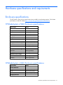
Hardware specifications and requirements .................................................................................... 51
Enclosure specifications............................................................................................................................ 51
HP BladeSystem c7000 Enclosure specifications................................................................................ 51
HP BladeSystem c3000 Enclosure specifications................................................................................ 51
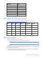
HP 10000 G2 rack specifications ............................................................................................................. 52
Rack requirements ................................................................................................................................... 52
Rack-free environment requirements ........................................................................................................... 53
Configuration scenarios............................................................................................................... 54
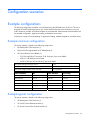
Example configurations ............................................................................................................................ 54
Example minimum configuration ...................................................................................................... 54
Example typical configuration ......................................................................................................... 54
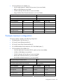
Example maximum configuration ..................................................................................................... 55
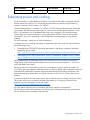
Estimating power and cooling................................................................................................................... 56
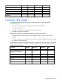
Estimating total weight ............................................................................................................................. 57
Preparing for installation.............................................................................................................. 58
Warning, caution, and important messages................................................................................................ 58
Additional rack considerations .................................................................................................................. 60
General component placement guidelines .................................................................................................. 60
Rack configuration software...................................................................................................................... 61
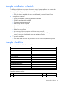
Sample installation schedule ..................................................................................................................... 62
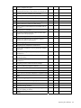
Sample checklists .................................................................................................................................... 62
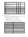
Delivery survey ....................................................................................................................................... 64
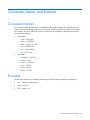
Conversion factors and formulas................................................................................................... 66
Conversion factors................................................................................................................................... 66
Contents
4
Formulas ................................................................................................................................................ 66
Technical support........................................................................................................................ 67
Before you contact HP.............................................................................................................................. 67
HP contact information ............................................................................................................................. 67
Acronyms and abbreviations........................................................................................................ 68
Glossary .................................................................................................................................... 70
Index......................................................................................................................................... 72
Contents
5
Introduction
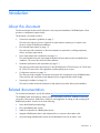
About this document
This document helps facilities and IT staff plan for the receipt and installation of HP BladeSystem c-Class
products in a dedicated computer facility.
The document is structured as follows:
•
General site preparation guidelines (on page 7)
This section provides an overview of general site requirements to prepare your computer room
facility to accept HP BladeSystem hardware.
•
Environmental requirements (on page 15)
This section provides information on the environmental site requirements, including temperature,
airflow, and space requirements.
•
Power requirements and considerations (on page 29)
This section details the power requirements and electrical factors that must be considered before
installation. This section also discusses PDU installation.
•
Hardware specifications and requirements (on page 51)
This section provides system specifications for the HP BladeSystem c7000 Enclosure, HP 10000 and
HP 10000 G2 series racks, and single-phase and three-phase power sources.
•
Configuration scenarios (on page 54)
This section provides examples of maximum and typical rack configurations using HP BladeSystem cClass products, and worksheets to help determine power usage and total solution weight.
•
Preparing for installation (on page 58)
This section includes tools and information to help prepare for product delivery and installation.
Related documentation
For the latest documentation, see the HP website (http://www.hp.com/go/bladesystem/documentation).
The HP BladeSystem documentation website includes white papers, tech briefs, installation instructions,
user guides, best practices, helpful hints, useful links, and suggestions for setting up and configuring HP
BladeSystem products. Use this site to do the following:
•
Learn about BladeSystem technology.
•
Plan a total BladeSystem solution.
•
Install the components of a BladeSystem solution.
•
Integrate a BladeSystem solution and understand how it connects to the outside world.
•
Use and manage a BladeSystem solution and understand the best way to make it work.
Introduction
6
General site preparation guidelines
ASHRAE guidelines for site planning
The American Society of Heating, Refrigerating and Air-Conditioning Engineers has published a common
set of guidelines for equipment manufacturers and data center designers to standardize on the following
issues relating to a data center site:
•
Operating environments for classes of equipment
•
Equipment placement for optimum reliability and airflow
•
Tests of performance and the operational health of the data center
•
Equipment installation evaluations
•
Methodology for reporting power, cooling, and environmental specifications
These guidelines were developed by an industry consortium, of which HP is a member. These guidelines
are presented in the 2004 report Thermal Guidelines for Data Processing Environments, which was
generated by the ASHRAE Technical Committee 9.9. For information about ASHRAE and the report, see
the ASHRAE website (http://www.ashrae.org).
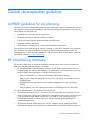
HP site planning assistance
HP provides a wide variety of site and environmental planning services that can help to evaluate your
data center site and install and configure your systems:
•
HP Quick Assessment for BladeSystem Environments—The HP BladeSystem Assessment Service is
designed to help you determine the capability of your data center environment to meet current and
future HP BladeSystem requirements, including the following services:
o
Help you understand how to utilize your data center resources more efficiently
o
Help you gain a better understanding of space, power, and cooling resource requirements for
HP BladeSystems
o
Recommend effective equipment racking orientation and placement for improved cooling
capacity
o
Help you plan for your future capacity requirements for HP BladeSystems in the data center
For a more detailed analysis, HP provides the following services:
•
HP Datacenter Assessment Service—This service provides a thorough review and analysis of your
facility's infrastructure. Findings are documented in a detailed final report. If risks or deficiencies are
found, a qualitative and quantitative explanation is provided for each, including prioritized
recommendations based on industry experience, industry standards, and engineering and
operational best practices.
•
HP Datacenter Thermal Assessment Service—The HP "intelligent cooling" approach leverages
sophisticated modeling tools and techniques to determine the unique thermal conditions within your
General site preparation guidelines 7
data center. HP Services professionals recommend changes to optimize climatic conditions and
reclaim capacity, postponing or even eliminating the need for costly mechanical upgrades. Choose
from three service levels to meet your specific requirements.
•
HP Datacenter Site Planning Service—Obtain a comprehensive site-preparation audit to help you
successfully integrate new equipment into your facility. Service deliverables include verification of
installation and service space, examination of the capacity and availability of your power
distribution system, analysis of cooling system capacity and airflow distribution, and a review of
installation readiness prerequisites. An in-depth report identifies any deficiencies and provides floorplan drawings locating equipment, receptacles, airflow panels, and cable cut-outs.
For more information, see the HP website (http://h20219.www2.hp.com/services/cache/114078-0-0225-121.aspx).
Site planning considerations
Customer facility managers and system administrators must discuss site planning, preparation, and system
installation before system delivery. A common understanding of environmental requirements and how the
systems will be delivered, configured, installed, and maintained helps to create a suitable data center and
aids the successful installation of the servers and related equipment.
It is important to plan the facility as a whole, not design based on calculations of individual system or
rack level requirements. Too many interdependencies in a modern data center make such simple
calculations unreliable. Designs and plans must be made for the data center as a whole, including all of
its equipment, with the realization that making one change in the data center environment can affect
many other physical, mechanical, and environmental aspects of the facility.
Take into account the requirements of third-party equipment and support equipment in the room. Dense
computing locations might have high power and cooling demands that could affect power and
environmental constraints. Be aware of rack positioning and airflow patterns. Ensure that the raised floor
space, cooling equipment, power supply equipment and generators, and other support equipment meet
the demands of all the servers and other mission-critical equipment.
Computer room preparation
Observe the following guidelines when preparing a computer room for product installation:
•
Locate the computer room away from the exterior walls of the building to avoid the heat gain from
windows and exterior wall surfaces.
•
When exterior windows are unavoidable, use windows that are double- or triple-glazed and shaded
to prevent direct sunlight from entering the computer room.
•
Maintain the computer room at a positive pressure relative to surrounding spaces.
•
Use a vapor barrier installed around the entire computer room envelope to restrain moisture
migration.
•
Caulk and vapor seal all pipe, conduit, and cable computer room entry and exit points.
•
In underfloor distribution installations, install at least a 610 mm (24 in) raised floor system for
optimum room air distribution.
•
Ensure a minimum clearance of 457 mm (18 in) between the top of the rack and the ceiling to allow
for return airflow.
General site preparation guidelines 8
•
Ensure that all ceiling tiles are in place.
•
Ensure a minimum of 457 mm (18 in) or local code minimum clearance, whichever is larger, from
the top of the rack to the fire sprinkler heads.
Cooling requirements
Air conditioning equipment requirements and recommendations are described in the following sections.
Basic air conditioning equipment requirements
The cooling capacity of the installed air conditioning equipment for the computer room should be
sufficient to offset the computer equipment dissipation loads, as well as any space envelope heat gain.
This equipment should include the following:
•
Air filtration
•
Temperature control
•
Humidity control
•
Air distribution
•
System controls adequate to monitor and maintain the computer room within specified operating
ranges
Lighting and personnel heat loads must also be included when calculating the total heat load for the
computer room. For example, a person dissipates about 450 BTU/h while performing a typical computer
room task.
Air conditioning system guidelines
HP recommends the following guidelines when designing a computer room air conditioning system and
selecting the necessary equipment:
•
Design the air conditioning system for 24-hour-a-day, 365-day-a-year operation.
•
Provide an air conditioning system that is independent of other systems in the building.
•
Provide one of the following:
o
A redundant air conditioning system
o
Sufficient extra cooling capacity to ensure availability of the computer equipment if a partial air
conditioning system failure occurs
•
Provide space and facilities for future system expansion.
•
Specify air conditioning equipment air filters with a minimum rating of 45 percent (based on
ASHRAE Standard 52-76, Dust Spot Efficiency Test).
Air conditioning system types
HP recommends the following air conditioning system types:
•
Chilled water package unit with remote chilled water plant
•
Air cooled package unit with remote air cooled chilling plant
General site preparation guidelines 9
•
Direct-expansion refrigerant-based unit with remote air-cooled condensers
•
Direct-expansion refrigerant-based unit with glycol cold condensers
An increasing number of in-row cooling solutions as well as water-cooled cabinets are available.
Basic air distribution systems
A basic air distribution system includes supply air and return air.
An air distribution system should be zoned to deliver an adequate amount of supply air to the cooling air
intake vents of the racks. Supply air temperature should be maintained within the following parameters:
•
Ceiling supply system—From 12.8°C to 15.6ºC (55°F to 60°F)
•
Floor supply system—At least 15.6°C (60°F)
If a ceiling plenum return air system or a ducted ceiling return air system is used, the return air grill(s) in
the ceiling should be above the exhaust area or the exhaust row.
The following three types of air distribution system are listed in order of recommendation:
•
Underfloor air distribution system—Downflow air conditioning equipment located on the raised floor
of the computer room uses the cavity beneath the raised floor as a plenum for the supply air.
Return air from an underfloor air distribution system can be DRA above the ceiling.
Perforated floor panels (available from the raised floor manufacturer) should be located around the
front of the system cabinets. Supply air emitted though the perforated floor panels is then available
near the cooling air intake vents of the racks.
•
Ceiling plenum air distribution system—Supply air is ducted into the ceiling plenum from upflow air
conditioning equipment located in the computer room or from an air handling unit (remote).
The ceiling construction should resist air leakage. Place perforated ceiling panels (with down
discharge air flow characteristics) around the front of the system cabinets. The supply air emitted
downward from the perforated ceiling panels is then available near the cooling air intake vents of
the racks.
Return air should be ducted back to the air conditioning equipment though the return air duct above
the ceiling.
•
Above ceiling ducted air distribution system—Supply air is ducted into a ceiling diffuser system from
upflow air conditioning equipment located in the computer room or from an air handling unit
(remote).
Return air from an above ceiling ducted air distribution system can be DRA above the ceiling, or
CPRA.
Adjust the supply air diffuser system grilles to direct the cooling air downward around the front of the
racks. The supply air is then available near the cooling air intake vents of the racks.
Air conditioning system specifications
All air conditioning equipment, materials, and installation must comply with any applicable construction
codes. Installation of the various components of the air conditioning system must also conform to the air
conditioning equipment manufacturer’s recommendations.
General site preparation guidelines 10
Air conditioning ducts
Use separate computer room air conditioning duct work. If it is not separate from the rest of the building,
it might be difficult to control cooling and air pressure levels. Duct work seals are important for
maintaining a balanced air conditioning system and high static air pressure. Adequate cooling capacity
means little if the direction and rate of air flow cannot be controlled because of poor duct sealing. Also,
the ducts should not be exposed to warm air, otherwise humidity levels can increase.
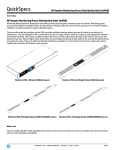
Cabling requirements
HP recommends using overhead cabling systems in high-density environments. Placing the cables in
overhead raceways maximizes airflow and makes access for servicing and upgrades more efficient.
The cable lengths are determined by the cabling specifications for the type of interconnect to which they
are attached. When planning the cable installation, ensure the following:
•
Cable lengths are less than the maximum allowable cable length for the cable and interconnect type.
•
Cable bend radii are greater than the minimum for the cable type used.
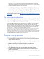
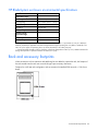
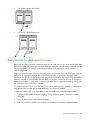
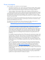
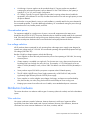
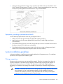
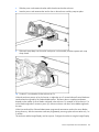
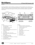
To determine the routing restrictions, do the following:
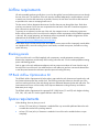
1.
Determine the cable length limits for a specific model of interconnect.
2.
Estimate the cabling constraints for interrack connections, referring to the example presented in the
following figure where:
o
A = rack height (such as 2 m for a 42U rack)
o
B = distance from the bottom of the rack to the underfloor trough or raceway
o
C = distance to the overhead cable raceway
o
D = distance between the racks
In the following figure, examples of the maximum cable run distances are shown by the dotted lines
labeled Overhead and Underfloor.
General site preparation guidelines 11
Floor loading
The computer room floor must be able to support the total weight of the installed components as well as
the weight of the individual racks as they are moved into position.
Floor loading is usually not an issue in nonraised floor installations. The information presented in this
section is directed toward raised floor installations.
An appropriate floor system consultant should verify any floor system under consideration for installation.
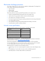
Raised floor loading
Raised floor loading is a function of the manufacturer’s load specification and the positioning of the
equipment relative to the raised floor grid. While HP cannot assume responsibility for determining the
suitability of a particular raised floor system, it does provide information and illustrations for the customer
or local agencies to determine installation requirements.
Rack static and dynamic loads are detailed below:
Rack
Static load
Dynamic load
Notes
HP 10636G2
908 kg (2000 lb)
690 kg (1520 lb)
Includes rack weight
HP 10642G2
908 kg (2000 lb)
908 kg (2000 lb)
Includes rack weight
HP 10647G2
908 kg (2000 lb)
—
Cannot ship with equipment installed
HP 10842G2
908 kg (2000 lb)
454 kg (1000 lb)
—
For more information, see the following websites:
•
Best practices for HP 10000 Series and HP 10000 G2 Series Racks on the HP website
(http://h20000.www2.hp.com/bc/docs/support/SupportManual/c00883424/c00883424.pdf).
•
Rack and power page on the HP website (http://www.hp.com/go/rackandpower).
HP recommends the following guidelines:
•
Because many raised floor systems do not have grid stringers between floor stands, the lateral
support for the floor stands depends on adjacent panels being in place. To avoid compromising this
type of floor system while gaining under-floor access, remove only one floor panel at a time.
•
Larger floor grids (bigger panels) are generally rated for lighter loads.
CAUTION: Do not position or install any equipment cabinets on the raised floor system until
you have carefully examined it to verify that it is adequate to support the installation.
Average floor loading
The average floor load value is not appropriate for addressing raised floor ratings at the floor grid
spacing level. However, it is useful for determining floor loading at the building level, such as the area of
solid floor or span of raised floor tiles covered by the rack footprint.
General site preparation guidelines 12
Computer room safety
Inside the computer room, fire protection and adequate lighting (for equipment servicing) are important
safety considerations. Federal and local safety codes that govern equipment installations.
Installation and maintenance precautions
To reduce the risk of electric shock or damage to the equipment when installing, maintaining, or servicing
Enterprise products, observe the following general precautions:
•
Provide overhead clearance for fire sprinkler devices—A minimum clearance is required between the
top of the rack and any fire protection sprinkler devices. Check the local building code for details.
•
Be aware of power voltages and use trained personnel—Some Enterprise products are capable of
producing hazardous voltages and hazardous energy levels. The installation of internal options and
routine maintenance and service of these products should be performed only by individuals who are
familiar with the procedures, precautions, and hazards associated with this type of equipment.
•
Secure all equipment—Rack equipment should be operated only with all enclosures in place and
properly secured. Always refer to the equipment installation guide and observe all applicable
warnings and precautions.
•
Follow manufacturer instructions—Always refer to the individual equipment installation instructions
for any special considerations when installing equipment in a rack.
Fire protection
The National Fire Protection Association's Standard for the Protection of Electronic Computer Data
Processing Equipment, NFPA 75, contains information on safety monitoring equipment for computer
rooms.
Most computer room installations are equipped with the following fire protection devices:
•
Smoke detectors
•
Fire and temperature alarms
•
Fire extinguishing system
•
Air handling (plenum) space that is segmented from the remainder of the building
Additional safety devices:
•
Circuit breakers
•
An emergency power cutoff switch
•
Devices specific to geographic location (such as earthquake protection)
Fire suppression
Though fires in computer rooms are rare, they are a critical safety and business consideration. HP
recommends the use of gaseous agents as primary fire control, with water as a backup system. Gaseous
agents include CO2, and Halon substitutes, like Intergen. Where fire suppression using water is dictated,
HP recommends the use of dry pipe water valving, with suitably rated temperature heads. Dry pipe water
valving lowers the business risks associated with accidental water pipe discharge.
General site preparation guidelines 13
Lighting requirements for equipment servicing
Adequate lighting and utility outlets in a computer room reduce the possibility of accidents and improve
efficiency during equipment servicing. The minimum recommended illumination level is 756 lm/m2 (70
foot candles) when the light level is measured at 762 mm (30 in) above the floor.
Occupancy-controlled lighting, with manual override switches for use during extended occupancy periods
or for servicing, is more efficient and less costly. For example, adequate lighting reduces the chance of
connector damage when cables are installed or removed. The HP Rack Light Kit (part number 361589B21) can also be installed at the rear of the rack to ensure adequate lighting is available.
Working space for component access
The recommended working space for performing maintenance is 1.2 m (4 ft) from either side of, in front
of, or behind the server. The work space must permit at least a 90 degree opening of equipment doors or
hinged panels. When planning for the working space area, consider whether access to the server will be
at the front, the side, or the rear of the component.
General site preparation guidelines 14
Environmental requirements
Environmental elements
The following environmental elements can affect HP BladeSystem c-Class product installation.
Humidity level
Maintaining proper humidity levels in the computer room is essential for reliable equipment performance.
Humidity levels outside the recommended range of 25 to 45 percent, especially if these levels are
sustained, lead to equipment damage and result in equipment malfunction through several mechanisms.
High humidity levels enable galvanic activity to occur between dissimilar metals. Galvanic activity can
cause high resistance to develop between connections and lead to equipment malfunctions and failures.
Extended periods of humidity levels greater than 60% have also been shown to adversely affect modern
printed circuit board reliability. High humidity can also adversely affect some magnetic tapes and paper
media.
High humidity levels are often the result of malfunctioning facility air conditioning systems. High humidity
can also be the result of facility expansion in excess of air conditioning system capacity.
Humidity levels below the minimum recommended value can also have undesirable effects. Low humidity
contributes to high ESD voltage potentials. ESD events can cause component damage during service
operations and equipment malfunction or damage during normal operation. Low humidity levels can
reduce the effectiveness of static dissipating materials and have also been shown to cause high speed
printer paper feed problems.
Low humidity levels are often the result of the facility heating system and occur during the cold season.
Most heating systems cause air to have a low humidity level, unless the system has a built-in humidifier.
ASHRAE and representatives of IT equipment manufacturers recommend a range of 18°C dry bulb with a
5.5°C dew point temperature to 27°C dry bulb with a 5.5°C dew point temperature. Over this range of
dry bulb temperature with a 5.5°C dew point, the relative humidity varies from approximately 25% to
45%.
For more information on humidity levels, see the ASHRAE website (http://www.ashrae.org/).
Dust and pollution
Dust and microscopic particles in the site environment adversely affect computer equipment. Airborne
abrasive particles can cause bearing failures in disk drives, tape drives, and other mechanical devices.
Dust may also blanket electronic components and printed circuit boards, causing premature failure
because of excess heat, humidity buildup, or both.
Conductive metallic particles can cause power supply and other electronic component failures. A build-up
of these metallic particles over time can cause short circuits on the densely packed circuit boards common
in modern electronics. Use every effort to ensure that the environment is as dust- and particulate-free as
possible. See "Metallic particulate contamination (on page 16)."
Environmental requirements 15
Smaller particles can pass through some filters, and over time, cause problems in mechanical parts.
Selection of the appropriate filter media and maintaining the air conditioning system at a high static air
pressure level can prevent small dust particles from entering the computer room.
Other dust, metallic, conductive, abrasive, or microscopic particles can result from the following sources:
•
Subfloor shedding
•
Raised floor shedding
•
Ceiling tile shedding
These particulates are not always visible to the naked eye. A good method to determine their possible
presence is to check the underside of the tiles. The tile should be shiny, galvanized, and free from rust.
To minimize dust and pollution in the computer room, observe the following guidelines:
•
Smoking—Establish a no-smoking policy. Cigarette smoke particles are eight times larger than the
clearance between disk drive read/write heads and the disk surface.
•
Printer location—Locate printers and paper products in a separate room to eliminate paper
particulate problems.
•
Eating or drinking—Establish a no-eating or drinking policy. Spilled liquids can cause short circuits
in equipment such as keyboards.
•
Floor cleaning—Use a dust-absorbent cloth mop rather than a dry mop to clean tile floors.
Special precautions are necessary if the computer room is near a source of air pollution. Some air
pollutants, especially hydrogen sulfide (H2S), are not only highly toxic and unpleasant but corrosive as
well. Hydrogen sulfide damages wiring and electronic equipment. The use of activated charcoal filters
reduces this form of air pollution.
Metallic particulate contamination
Metallic particulates can be especially harmful around electronic equipment. This type of contamination
can enter the data center environment from a variety of sources, including but not limited to raised floor
tiles, worn air conditioning parts, heating ducts, rotor brushes in vacuum cleaners, or printer component
wear. Because metallic particulates conduct electricity, they have an increased potential for creating short
circuits in electronic equipment. This problem is exaggerated by the increasingly dense circuitry of
electronic equipment.
Over time, very fine whiskers of pure metal can form on electroplated zinc, cadmium, or tin surfaces. If
these whiskers are disturbed, they may break off and become airborne, possibly causing failures or
operational interruptions. For more than 50 years, the electronics industry has been aware of the
relatively rare but possible threat posed by metallic particulate contamination. During recent years, a
growing concern has developed in computer rooms where these conductive contaminants are formed on
the bottom of some raised floor tiles.
Although this problem is relatively rare, it may be an issue within your computer room. Because metallic
contamination can cause permanent or intermittent failures on your electronic equipment, HP strongly
recommends that your site be evaluated for metallic particulate contamination before installation of
electronic equipment.
Environmental requirements 16
Electrostatic discharge prevention
Static charges (voltage levels) occur when objects are separated or rubbed together. The voltage level of
a static charge is determined by the following factors:
•
Types of materials
•
Relative humidity
•
Rate of change or separation
Follow these precautions to minimize possible ESD-induced failures in the computer room:
•
Maintain recommended humidity level and airflow rates in the computer room.
•
Install conductive flooring (conductive adhesive must be used when laying tiles).
•
Use conductive wax if waxed floors are necessary.
•
Ensure that all equipment and flooring are properly grounded and are at the same ground potential.
•
Use conductive tables and chairs.
•
Use a grounded wrist strap (or other grounding method) when handling circuit boards.
•
Store spare electronic modules in antistatic containers.
Acoustic noise specification
Declared noise emission values for the c7000 enclosure in accordance with ISO 9296:
Specification
Value
Declared sound power level, LWAd Bels
Idle
7.5
Operating
7.5
Declared sound pressure level, LpAm dBA
Idle
57
Operating
57
Detailed information on conformance to country Technical Regulations and certificates of conformance
can be found on the HP website (http://www.hp.com/go/certificates).
These levels are appropriate for dedicated computer room environments, not office environments.
You must understand the acoustic noise specifications relative to operator positions within the computer
room when adding additional systems to computer rooms with existing noise sources.
Ambient noise level in a computer room can be reduced as follows:
•
Dropped ceiling—Cover with a commercial grade of fire-resistant, acoustic rated, fiberglass ceiling
tile.
•
Sound deadening—Cover the walls with curtains or other sound deadening material.
•
Removable partitions—Use foam rubber models for most effectiveness.
Environmental requirements 17
Recommended operating environment
To help ensure continued safe and reliable equipment operation, install or position the rack in a well
ventilated, climate-controlled environment.
Air inlet temperature to the rack should be between 20 to 25ºC under normal operating conditions in the
data center, per ASHRAE standard TG9 HDEC.
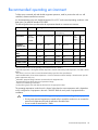
The following table shows product technical requirements based on customer environments.
Operating Environment (ambient)1
Temperature (ºC, dry bulb)2
Environment
ASHRAE
Allowable4 Recommended6 Allowable5 Recommended6 Dew
,5
point
(max)7
Rate of
chg
(ºC/hr,
max)
1
15 to 32
20 to 25
20 to 80
40 to 55
17
5
Controlled office 2
10 to 35
20 to 25
20 to 80
40 to 55
21
5
Uncontrolled
office
3
5 to 35
NA
8
8 to 85
NA
8
28
NA8
Home
3
5 to 35
NA8
8 to 85
NA8
28
NA8
Light industrial
4
5 to 40
NA8
8 to 90
NA8
28
NA8
Portable/mobile 4
5 to 40
NA8
8 to 90
NA8
28
NA8
Controlled
computer room
Special
Industry
equivalent3
Relative humidity %;
noncondensing
Product specifications are controlled by contract or other requirements.
The maximum elevation for all operating environmental classes is 3050 m.
Dry bulb temperature is the regular ambient temperature. Derate maximum dry bulb temperature 1ºC/300 m above
900 m.
3
The values in each row meet or exceed the stated industry equivalent class specifications.
4
With installed media, the minimum temperature is 10ºC and maximum relative humidity is limited to 80%. Specific
media requirements may vary.
5
Allowable: equipment design extremes as measured at the equipment inlet.
6
Recommended: target facility design and operational range.
7
Must be noncondensing environment.
8
Local product groups must make business decisions for the appropriate values.
1
2
The operating temperature inside the rack is always higher than the room temperature and is dependent
on the configuration of equipment in the rack. Check the TMRA for each piece of equipment before
installation.
CAUTION: To reduce the risk of damage to the equipment when installing third-party options:
• Do not permit optional equipment to impede airflow around the enclosure or to increase the
internal rack temperature beyond the maximum allowable limits.
• Do not exceed the manufacturer’s TMRA.
Environmental requirements 18
Airflow requirements
HP rack-mountable products typically draw in cool air through the front and exhaust warm air out through
the rear of the rack. The front door of the rack must be ventilated adequately to enable ambient room air
to enter the rack with as little restriction as possible. Likewise, the rear door must offer as little restriction
as possible to the warm air escaping from the rack.
The free area of a door determines the amount of airflow that can pass through the doors. Rack doors
must have a minimum of 63% free area compared to the total area of the door. Some doors appear to
have sufficient free area but do not.
To prevent air recirculation from the rear of the rack, the computer room air conditioning system must
deliver sufficient airflow to the front of the rack to meet the airflow requirements of the installed equipment
in the rack. Idle, normal operating, and maximum airflow requirements for blade configurations can be
obtained from the HP Blade Power Sizer on the HP website
(http://www.hp.com/go/bladesystem/powercalculator).
Route cables away from fans and air inlets and outlets to ensure proper airflow. Improperly routed cables
can impede airflow, cause the cooling fans to work harder, consume more power, and reduce cooling
system efficiency.
Blanking panels
If the front of the rack is not filled completely with components, unused equipment mounting space
between the components can adversely affect cooling within the rack. Cover unused equipment mounting
space with blanking panels.
Seal air gaps in the rack and between adjacent racks to prevent recirculation of hot-air from the rear of
the rack to the front of the rack. Use cable brushes to seal cable entry and exit cutouts and cabinet fillers
to seal the space between the cabinets to provide improved cooling efficiency.
HP Rack Airflow Optimization Kit
The HP Rack Airflow Optimization Kit helps seal air gaps inside the rack, between two bayed racks, and
the clearance between the floor and the rack. The kit also prevents hot exhaust air from the rear of the
rack from reaching the front of the rack through pressure differential between the hot and cold aisles. This
feature maximizes server cold air intake, which improves datacenter cooling efficiency and reduces
datacenter power usage.
The HP Rack Airflow Optimization Kit supports all HP 10000 Series (G1 and G2) rack heights including
22U, 36U, 42U, and 47U. It also supports 800-mm wide HP racks.
Space requirements
When deciding where to place your rack:
•
At least 1219 mm (48 in) of clearance is needed all the way around the pallet and above the rack
to enable the removal of the packing material.
•
At least 1219 mm (48 in) of clearance is needed in front of the rack to enable the door to open
completely.
Environmental requirements 19
•
At least 762 mm (30 in) of clearance is needed in the rear of the rack to provide access to
components.
•
At least 380 mm (15 in) of clearance is needed around a power supply to facilitate servicing.
For more information, see "Working space for component access (on page 14)".
Delivery space requirements
There should be enough clearance to move equipment safely from the receiving area to the computer
room. Permanent obstructions, such as pillars or narrow doorways, can cause equipment damage.
Delivery plans should include the possible removal of walls or doors.
Operational space requirements
Other factors must be considered along with the basic equipment dimensions. Reduced airflow around
equipment causes overheating, which can lead to equipment failure. Therefore, the location and
orientation of air conditioning ducts, as well as airflow direction, are important. Obstructions to
equipment intake or exhaust airflow must be eliminated.
CAUTION: Do not block venting holes in the covers or side panels. Proper airflow is required
to prevent overheating of the unit.
The locations of lighting fixtures and utility outlets affect servicing operations. Plan equipment layout to
take advantage of lighting and utility outlets. Do not forget to include clearance for opening and closing
equipment doors.
Clearance at the front and rear of the racks must also be provided for proper cooling airflow through the
equipment.
If other equipment is located so that it exhausts heated air near the cooling air intakes of the racks, larger
space requirements are needed to keep ambient air intake to the racks and equipment within the
specified temperature and humidity ranges.
Space planning should also include the possible addition of equipment or other changes in space
requirements. Equipment layout plans should also include provisions for the following:
•
Channels or fixtures used for routing data cables and power cables
•
Access to air conditioning ducts, filters, lighting, and electrical power hardware
•
Power conditioning equipment
•
Cabinets for cleaning materials
•
Maintenance area and spare parts
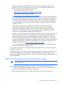
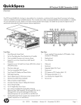
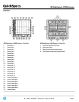
Equipment clearance and floor loading
A clearance of 1219 mm (48 in) in front of a configured rack and 762 mm (30 in) to the rear of a
configured rack is recommended. All buildings and raised computer room floors are engineered to
provide a specific floor loading.
Environmental requirements 20
WARNING: When configuring a solution, make sure that the floor loading specifications are
followed. Failure to do so can result in physical injury or damage to the equipment and the
facility.
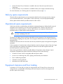
10000 and 10000 G2 Series Rack footprint (600 mm [24 in] wide)
10000 Series Rack footprint (800 mm [31.5 in] wide)
Floor plan grid
A floor plan grid is used to plan the location of equipment in the computer room. In addition to its use for
planning, the floor plan grid should also be used when planning the locations of the following items:
•
Air conditioning vents
•
Lighting fixtures
•
Utility outlets
•
Doors
•
Access areas for power wiring and air conditioning filters
•
Equipment cable routing
Environmental requirements 21
HP BladeSystem enclosure environmental specifications
Specification
Value
Temperature range*
Operating
10°C to 35°C (50°F to 95°F)
Non-operating
-30°C to 60°C (-22°F to 140°F)
Wet bulb temperature
Operating
28ºC (82.4ºF)
Non-operating
38.7ºC (101.7ºF)
Relative humidity
(noncondensing)**
Operating
20% to 80%
Non-operating
5% to 95%
* All temperature ratings shown are for sea level. An altitude derating of 1°C per 304.8 m (1.8°F per 1000 ft) to
3048 m (10,000 ft) is applicable. No direct sunlight allowed. Upper operating limit is 3,048 m (10,000 ft) or 70
kPa/10.1 psia. Upper non-operating limit is 9,144 m (30,000 ft) or 30.3 kPa (4.4 psia).
** Storage maximum humidity of 95% is based on a maximum temperature of 45°C (113°F). Altitude maximum for
storage corresponds to a pressure minimum of 70 kPa (10.1 psia).
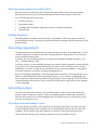
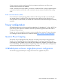
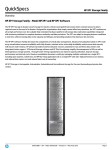
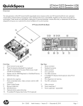
Rack and accessory footprints
When accessories such as extensions and stabilizing kits are added to a particular rack, the footprint of
the rack extends into the rack rear row and infringes upon necessary clearances.
Footprint for a 600 mm rack configuration with an extension kit installed (598 mm wide x 1184.9 mm
deep):
Environmental requirements 22
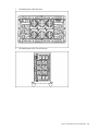
Footprint for a 600 mm rack configuration with an extension and standard stabilizer kit installed (1001.5
mm wide x 1390.0 mm deep):
Footprint for a 600 mm rack configuration with an extension and heavy duty stabilizer kit installed
(1001.5 mm wide x 1414.7 mm deep):
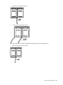
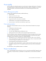
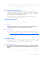
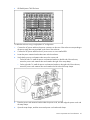
Front door clearance
When racks are bayed together, the design of the front door limits the extent to which the rack door on
the right can open. If there is not sufficient work space, open the door on the left side or remove the door
from the rack being serviced. Slight differences exist between the opening allowances of the 10000 and
10000 G2 Series Racks because of the different geometries and construction of the doors.
Front door clearance for 10000 Series Racks configured with 600 mm baying brackets is:
Environmental requirements 23
•
90º access with one door closed
•
120º access with both doors open
Front door clearance for 10000 Series Racks configured with 24-in baying brackets is:
•
102º access with one door closed
Environmental requirements 24
•
120º access with both doors open
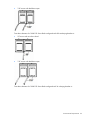
Front door clearance for 10000 G2 Series Racks configured with 600 mm baying brackets is:
•
95º access with one door closed
•
118º access with both doors open
Front door clearance for 10000 G2 Series Racks configured with 24 in baying brackets is:
Environmental requirements 25
•
108º access with one door closed
•
118º access with both doors open
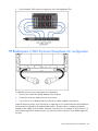
Best practices for deployment in rows
Baying kits are used to physically connect adjacent racks to create a row of two or more units. Racks that
are bayed together with a baying kit are more stable and reduce the potential tipping of the rack. If racks
are secured together with baying kits, the side feet installed on each end of the row of racks are
considered optional.
If gaps are created between racks that could allow airflow from the rear of the rack, these gaps should be
sealed with an appropriate material that will not cause particulate or electro-static discharge issues.
Fixed stabilizers are anti-tip side feet (front and side) that provide stability and support when equipment is
installed, removed, or accessed within the rack. Rack rows with four or more bayed racks do not need a
stabilizer kit installed. For single racks or bays of three racks, with no component exceeding 100 kg (220
lb), a standard 600 mm stabilizer is required.
If a standard 600 mm (23.62 in) or 800 mm (31.50 in) front stabilizing foot is installed on a stand-alone
rack, the side feet, provided with the fixed stabilizer kit, should also be installed.
A heavy duty 600 mm (23.62 in) front stabilizer foot is required in any of the following situations:
•
A single rack-mountable component weighing 100 kg (220 lb) or greater is installed in a standalone rack.
•
A row of three or fewer racks are bayed together.
•
Side feet, which are included in the stabilizer kits, should also be installed to stabilize the rack.
Environmental requirements 26
Rack placement and arrangement for proper airflow
Racks must be placed and arranged properly in the data center to provide sufficient airflow and
clearance for access to the rack.
In the front of the rack, a clearance of 1219 mm (48 in) is required. This requirement applies to individual
rack installations as well as when aligning rack rows so that the front doors are facing each other.
In the rear of the rack, a clearance of 762 mm (30 in) is required to provide space for servicing the rack.
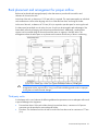
If a data center has multiple rows of racks, the rows of racks can be arranged to take advantage of the
front-to-back airflow by arranging racks front-to-front and back-to-back. Additionally, conditioned air
registers can be oriented along the front aisles and the return air registers in the back aisles. This
arrangement utilizes the aisle space as air plenums and increases the efficiency of the air conditioning.
CAUTION: Always use blanking panels to fill empty vertical spaces in the rack. This
arrangement ensures proper airflow. Using a rack without blanking panels results in improper
cooling that can lead to thermal damage.
Third-party racks
If a third-party rack is used, observe the following additional requirements to ensure adequate airflow and
to prevent damage to the equipment:
•
Front and rear doors: If the rack includes closing front and rear doors, a minimum of 65 percent
open area must be provided to ensure adequate airflow.
•
Front door: The clearance from face of rack to inside of the front door must be a minimum of 77 mm
(3 in).
Environmental requirements 27
•
Rear door: The clearance between the rear of the enclosure and the rear rack door must be a
minimum of 175 mm (6.9 in) to accommodate system cabling.
•
Side: The clearance between the installed rack component and the side panels of the rack must be a
minimum of 70 mm (2.75 in).
•
Width: 483 mm (19 in)
•
Depth: Maximum clearance between front and rear RETMA rails is 864 mm (34 in). Minimum
clearance for round-hole racks is 627 mm (24.7 in). Minimum clearance for square-hole racks is
635 mm (25 in).
•
The rack must be able to accept the adjustable rack rails that are shipped with each enclosure:
o
Minimum rail length: 635 mm (25 in)
o
Maximum rail length: 864 mm (34 in)
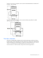
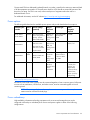
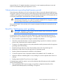
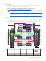
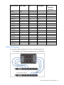
Rack tie-down option kit
The HP 10000 G2 Series Rack Tie-Down Option Kit enables you to secure HP 10000 G2 Series Racks to
the floor.
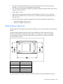
The following table indicates where the holes are to be drilled to secure the rack to the floor. The
distances are measured from the holes on the tie-downs. To drill your holes, contact your building
structural engineer. After your holes have been drilled, insert a bolt with a washer into each hole,
securing the rack to the floor.
Callout
600W distance
A
470 mm (18.0 in)
B
235 mm (9.3 in)
C
987.1 mm (38.9 in)
D
231 mm (9.1 in)
E
462 mm (18.2 in)
For more information, see the HP 10000 G2 Series Rack Tie-Down Option Kit Installation Instructions.
Environmental requirements 28
Power requirements and considerations
Power requirements
When planning power distribution requirements, observe the following:
•
The power load must be balanced between available AC supply branch circuits.
•
The AC current load attached to a branch circuit must not exceed 80 percent of that branch circuit
current rating.
•
If a UPS system is used, when the peak load reaches 90 percent of the non-redundant UPS system
capacity, no new loads can be installed until the UPS system capacity is increased.
Installation of this equipment must be performed by licensed electricians and must comply with local and
regional electrical regulations governing the installation of IT equipment. This equipment is designed to
operate in installations covered by NFPA-70 (National Electric Code) and NFPA-75 (code for Protection
of Electronic Computer/Data Processing Equipment). For electrical power ratings on options, refer to the
product rating label or the user documentation supplied with that option
WARNING: To reduce the risk of personal injury, fire, or damage to the equipment, do not
overload the AC supply branch circuit that provides power to the rack. Consult the electrical
authority having jurisdiction over wiring and installation requirements of your facility.
CAUTION: Protect the enclosure from power fluctuations and temporary interruptions with a
regulating UPS. This device protects the hardware from damage caused by power surges and
voltage spikes and keeps the enclosure in operation during a power failure.
Electrical factors
Proper design and installation of a server power distribution system requires specialized skills. Those
responsible for this task must have a thorough knowledge of appropriate electrical codes and the
limitations of the power systems for computer and data processing equipment.
A well designed power distribution system exceeds the requirements of most electrical codes. A good
design, when coupled with proper installation practices, produces the most trouble-free operation.
A detailed discussion of power distribution system design and installation is beyond the scope of this
document. However, electrical factors relating to power distribution system design and installation must be
considered during the site preparation process.
IMPORTANT: Electrical practices and suggestions in this guide are based on North America
practices. For regions and areas outside North America, local electrical codes take
precedence over North American electrical codes.
Local authority has jurisdiction (LAHJ) and should make the final decision regarding adherence
to region-specific or area-specific electrical codes and guidelines.
Power requirements and considerations 29
Power consumption
Power consumption can be divided into two broad categories:
•
Marked electrical amperage, which is listed on the required safety and regulatory labels, generally
represents the maximum current draw that the marked device could achieve. Safety and regulatory
labels on computer equipment list the ratings for maximum power consumption conditions.
•
Typical consumption, which is measured under normal circumstances, should be used only in
customer calculations with UPS and air conditioning sizing where remaining capacities are needed.
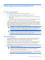
When determining the necessary electrical infrastructure required, consider several factors. The first and
most important area is the local electrical and regulatory codes. The installation must meet or exceed
these codes. The local authority has jurisdiction and makes the final decision as to whether an installation
conforms to the relevant codes.
In North America the relevant code is National Electrical Code 2005 Article 210 and Article 645, which
states the continuous measured load should not exceed 80 percent of the rated circuit maximum, where
continuous load is defined as 3 hours or more.
This method leaves some flexibility to the infrastructure designer and includes several options for
determining power requirements, which are discussed in the following bullets.
NOTE: The following scenarios use North America circuit sizes and voltages.
•
Size the electrical infrastructure according to the label ratings, even though this could mean the
electrical infrastructure might be oversized. Typically the power supply is sized to provide the
maximum power consumption throughout the life of system. Additionally the power supply might be
used in multiple systems, and therefore must be sized to the maximum configuration of the largest
system into which it can be installed. Sizing the electrical infrastructure to the power supply label
rating protects against ever overloading the electrical infrastructure, but typically results in overprovisioning.
As an example, due to the long lifecycle of the c7000 enclosure (5 years) the power supply is rated
at 2400W output, 2780VA input. When running in N+N redundant mode, according to the power
supply specifications, the system is rated at a maximum input power of 8340VA (2780VA x 3). To
deliver this much redundant power to an enclosure requires either two 50A single-phase circuits
(8320VA each) or two 30A three-phase circuits (8640VA each). Some extreme configurations can
simultaneously stress all 16 server blades to maximum load, which would use the full capacity of the
power supplies.
An order of magnitude calculation using the power supply ratings requires approximately 2MW
(8kW x 3) to be delivered to the racks. Full redundancy would require 4MW. The cost of the UPS
equipment, transformers, switchgear, generators, and other infrastructure to provide 4MW is
significant. The Uptime Institute (http://www.uptimeinstitute.org/) estimates that each watt of
redundant power costs between $23 and $25 depending on the level of redundancy required. For
typical environments, power usage would be between 750kW and 1.25MW, or 40% to 60% of the
available capacity.
Actual power usage is significantly lower because the vast majority of configurations running typical
customer applications do not generally exceed 5kVA peak power consumption. The average power
consumption is usually lower, typically between 3kVA and 4kVA. Sizing using nameplate values
typically results in significant amounts of wasted power capacity.
Power requirements and considerations 30
•
Use power sizing tools to calculate the infrastructure required as configured and allow some
flexibility for growth. HP provides power sizing tools for all its current industry standard servers.
These calculators can be found at the following locations:
o
For ML and DL products, on the HP website
(http://h30099.www3.hp.com/configurator/powercalcs.asp)
o
For BladeSystem products, on the HP website
(http://www.hp.com/go/bladesystem/powercalculator)
These tools provide a conservative estimate of power loading values at a given system utilization as
well as a theoretical maximum load that the system could achieve as configured. Use of these tools
allows the infrastructure designer to use realistic maximum values to estimate power loading and
circuit requirements. In this scenario, however, monitoring tools such as Insight Power Manager or
HP Monitored PDUs must be used to ensure that the continuous loads do not exceed 80 percent of
the rated circuit load.
•
Install devices in a test environment and measure the actual worst case loads running the
applications and loading that is specific to your environment, and then size the electrical
infrastructure accordingly. This method is the most accurate, but may not be practical for many
customers. This method would also require ongoing monitoring of the installation to ensure that
infrastructure is not overloaded as applications and loads change.
•
Manage the electrical load using several available HP BladeSystem features. A Dynamic Power Cap
can be set at the enclosure level. The Onboard Administrator actively manages the blade power
caps to ensure that the enclosure electrical load does not exceed the Dynamic Power Cap value
while optimizing blade performance. HP Power Regulator can be set to Static Low to reduce power
consumption, and together with Insight Power Manager can be used to provide policy-based power
management to ensure that circuits are not overloaded. For more information on Dynamic Power
Capping, see the HP website (http://www.hp.com/go/powercapping).
•
Size air conditioning and UPS devices with typical ratings, but account for overloading that could
take place with additional infrastructure growth.
HP recommends a cooling plan for the maximum rated power output of the room and a growth plan for
cooling the infrastructure.
When determining power requirements, always consider any peripheral equipment that will be installed
during initial installation or as a future upgrade. To determine the power required to support these
devices, see the applicable documentation for such devices. HP recommends using dedicated breakers for
peripheral equipment.
Electrical load requirements (circuit breaker sizing)
IMPORTANT: LAHJ is the final authority regarding adherence to country-specific electrical
codes and guidelines.
HP recommends derating the power distribution systems for one or both of the following reasons:
•
To avoid nuisance tripping from load shifts or power transients, do not run circuit protection devices
continuously above 80 percent of their RMS current ratings.
•
Safety agencies derate most power connectors to 80 percent of their RMS current ratings.
Power requirements and considerations 31
Power quality
Most HP products are designed to operate over a wide range of voltages and frequencies. The products
are tested and shown to comply with certain EMC Specifications. However, damage can occur if these
ranges are exceeded. Severe electrical disturbances can exceed the design specifications of the
equipment.
Factors affecting power quality
Common factors that affect power quality include the following:
•
Electrical storms
•
Utility service brownouts or sags
•
Faults in the power generation equipment
•
Large inductive loads, such as motors and welders
•
Load fluctuations occurring within the facility distribution system
•
Loose connections or other faults in the distribution system wiring
Power system protection
HP products can be protected from the sources of many of these electrical disturbances by using the
following:
•
A dedicated power distribution system
•
Power conditioning equipment
•
Over- and under-voltage protection and detection circuits
•
Lightning arresters on power cables to protect equipment against electrical storms
The power distribution system is designed to provide immunity to power interruptions. However, testing
cannot conclusively rule out loss of service. Use the following guidelines to provide the best possible
performance of power distribution systems for HP computer equipment:
•
Dedicated power source—Isolates the power distribution system from other circuits in the facility.
•
Online uninterruptible power supply (UPS)—Keeps input voltage to devices constant and should be
considered if outages of one-half cycle or more are common.
•
Auto-start generators–provide backup power to the UPS.
•
Missing-phase and low-voltage detectors—initiate a transfer of the UPS to generator power when a
severe power interruption occurs. For peripheral equipment, these devices are recommended but
optional.
For each situation, refer to qualified contractors or consultants.
Power considerations
Power is best managed within the rack by the use of one or more rack-mounted PDUs. Depending on the
configuration, it may be necessary or preferable to use multiple PDUs to connect all devices inside the
rack.
Power requirements and considerations 32
Connect each PDU to a dedicated (unshared) branch circuit that is rated for the continuous measured load
of all the equipment connected to it. The total power load for a PDU should not exceed 80 percent of the
branch circuit rating. If a PDU is not used, connect each piece of equipment within the rack to a
dedicated branch circuit.
For additional information, see the HP website http://www.hp.com/og/powercapping.
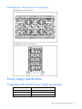
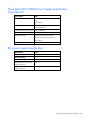
Power options
The following table describes the available power options and provide details about those options.
Enclosure part
number
Source
type
Source voltage
(nominal)
Plug or
connector
type
Circuit type
Power
receptacle
required
412136-B2x
3-phase
200 to 220 VAC
line to line (phase to
phase), 3-phase
delta 50Hz/60Hz
NEMA L1530p, 3-m
(10-ft) power
cord
30A 200/208V
Three-phase
delta
L15-30R
3-phase
346 VAC to 415
VAC line to line
IEC 309, 4pole, 5-wire,
Red, 3-m
(10-ft) power
cord
16A 346-415V
IEC 309, 4-Pole,
5-Wire, red
IEC 320
C19-C20
1.2-m
(4-ft) jumper
cord
16A Singlephase 100V to
120V or 200V
to 240V
IEC320-C19*
6.4mm
(0.25-in)
studs for bolt
down
conections
—
45DG 4AWG
1/4 2H (Twohole lug, 45degree bend,
6.4-mm (0.25-in)
stud hole size,
16-mm (0.63-in)
hole spacing)
412133-B2x
403318-B2x
403319-B2x
200 VAC to 240
VAC line to neutral
3-phase WYE
403320-B2x
403321-B2x
Singlephase
100V to 120V AC
200V to 240V AC
50Hz/60Hz
—
DC
-36 VDC to -72 VDC
*Additional power cords are available for single-phase solutions. See the HP Website
(http://www.hp.com/go/rackandpower).
All branch circuits used within a facility must be connected together to form a common ground. All power
sources such as transformers, UPS devices, and other sources, must be connected together to form a
common ground.
NOTE: When wiring a 3-phase enclosure, phase rotation is unimportant. However, the
rotation must be consistent for both plugs.
Power redundancy
High-availability information technology equipment such as servers and storage devices can be
configured with backup or redundant power sources and power supplies in either of the following
configurations:
Power requirements and considerations 33
•
N+N design: N power supplies can be provided where N/2 power supplies are capable of
sustaining the associated equipment's power demand. For the c7000 enclosure, this quantity is
typically a 2+2 or 3+3 power supply configuration.
•
N+1 design: Typically four power supplies are provided, requiring at least three to handle the
equipment's power demand. If one fails, the other three remain on line with enough capacity to meet
the power demand.
Be sure that the wiring and branch circuitry to each installation is suitably rated for the power demand of
the connected equipment. To provide additional redundancy, HP recommends routing the power through
separate branch circuits, breaker panels, and PDUs.
Non-redundant power
For equipment supplied by a single source of power, connect all components to the same power
distribution device (PDU or UPS). The power distribution device should be suitably rated for the connected
load. If the total load exceeds the rating of the power distribution device, obtain a suitable rated device
or add a second power distribution device and divide the load equally between the devices.
Line voltage selection
All HP products that are optimized for rack mounting have wide-range power supply inputs designed to
operate at a voltage range of 100-240V. HP recommends operating rack-optimized equipment with high
line voltage (200-240V AC).
Benefits of high line voltage operation include the following:
•
Power supplies run more efficiently and waste less power when operating at 200-240V, thus saving
electrical power.
•
Greater capacity is available in a single rack. For the same size circuit, almost twice the power can
be delivered to a rack at high line versus low line. For example, a 115V 30A branch circuit can
deliver 2760VA (de-rated) to a rack, while a 208V 30A branch can deliver 4992VA (de-rated) to a
rack.
•
Some products require 200-240V input power to operate at their full-rated capacity.
•
The HP 2400W High Efficiency Power Supply operates only at 200-240V AC and provides
significantly higher efficiency than the 2250W power supply.
•
Power supplies run cooler at higher input voltages, last longer, and improve overall availability.
Also, because they run cooler, they produce less heat which helps to lower cooling costs.
•
Keeping input currents lower allows the use of smaller, more standardized power connections.
Distribution hardware
This section describes wire selection and the types of raceways (electrical conduits) used in the distribution
system.
Wire selection
Use copper conductors instead of aluminum, because aluminum’s coefficient of expansion differs
significantly from that of other metals used in power hardware. Because of this difference, aluminum
conductors can cause connector hardware to work loose, overheat, and fail.
Power requirements and considerations 34
Raceway systems (electrical conduits) (LAHJ)
Raceways (electrical conduits) form part of the protective ground path for personnel and equipment.
Raceways protect the wiring from accidental damage and also provide a heatsink for the wires.
Any of the following types may be used:
•
EMT thin-wall tubing
•
Rigid (metal) conduit
•
Liquidtight with RFI shield grounded (most commonly used under raised floors)
•
Armored cable
Building distribution
All building feeders and branch circuitry should be in rigid metallic conduit with proper connectors (to
provide ground continuity). Conduit that is exposed and subject to damage should be constructed of rigid
galvanized steel.
Grounding requirements
This equipment must be grounded properly for proper operation and safety. In the United States, you must
install the equipment in accordance with NFPA 70 (National Electric Code), Article 250, as well as any
local and regional building codes.
In Canada, you must install the equipment in accordance with Canadian Standards Association, CSA
C22.1, Canadian Electrical Code.
In all other countries, you must install the equipment in accordance with any regional or national electrical
wiring codes, such as the International Electrotechnical Commission (IEC) Code 364, parts 1 through 7.
Furthermore, you must be sure that all power distribution devices used in the installation, such as branch
wiring and receptacles, are listed or certified grounding-type devices.
Because of the high ground-leakage currents associated with this equipment, HP recommends the use of a
PDU that is either permanently wired to the building’s branch circuit or includes a nondetachable cord
that is wired to an industrial-style plug. NEMA locking-style plugs or those complying with IEC 60309 are
considered suitable for this purpose. Using common power outlet strips to supply power to this equipment
is not recommended.
Grounding systems
HP systems are tested and certified only with grounding systems in which a neutral return path and a
protective earth are separate conductors without any inserted impedances. Additionally, the protective
earth and return neutral wires are shorted together at the XO bonding junction on the secondary side of
the newly derived power source.
Grounding and earth leakage current
For proper operation and safety, rack components must be properly grounded in accordance with any
local and regional building codes. Furthermore, be sure that all power distribution devices used in the
installation, such as branch wiring and receptacles, are Listed or Certified grounding-type devices.
Observe the following limits when connecting products to AC power distribution devices:
Power requirements and considerations 35
•
For UPS products and PDUs that have permanently attached AC power cords or are directly wired to
the building power, the total combined leakage current should not exceed 5 percent of the total input
current required for the connected products.
•
For UPS products and PDUs that have detachable AC power cords, the total combined leakage
current should not exceed 3.5 mA per PDU or UPS.
Power distribution safety grounding (LAHJ)
The power distribution safety grounding system consists of connecting various points in the power
distribution system to earth ground using green (green/yellow) wire ground conductors. When tied to
metal chassis parts that might be touched, these ground connections protect computer room personnel
against shock hazard from current leakage and fault conditions.
Power distribution systems consist of several parts. HP recommends that these parts be solidly
interconnected to provide an equipotential ground to all points.
Main building electrical ground
The main electrical service entrance equipment should have an earth ground connection, as required by
applicable codes. Connections such as a grounding rod, building steel, or a conductive type cold water
service pipe provide an earth ground.
Conduit bonding
Construct all electrical distribution systems of metallic conduit that is connected together securely or
bonded to panels and electrical boxes to provide a continuous grounding system.
Power panel ground
Each power panel should be grounded to the electrical service entrance with green (green/yellow) wire
ground conductors. The green (green/yellow) wire ground conductors should be sized per applicable
codes (based on circuit overcurrent device ratings).
NOTE: The green wire ground conductor can be a black wire with green tape (LAHJ).
Computer safety ground
Ground all computer equipment with the green (green/yellow) wire included in the branch circuitry. The
green (green/yellow) wire ground conductors should be connected to the appropriate power panel and
should be sized per applicable codes (based on circuit overcurrent device ratings).
Dual power source grounding
With dual power sources, both sources must have the same ground reference. Otherwise, an electrical
potential could exist that could be hazardous to personnel and might cause performance issues for the
equipment.
Because the dual power sources often originate from two different transformers or two different UPS
devices, use the same ground reference point to ground the secondary of each transformer or UPS device.
Measure the voltage potentials from ground pin to ground pin of these sources. Voltage levels that are
Power requirements and considerations 36
measured above 3.0 V might be hazardous to personnel or cause equipment performance issues and
must be corrected before placing the equipment in service.
Cabinet performance grounding (high frequency ground)
Some safety power distribution wires are too long and too inductive to provide adequate high-frequency
return paths. Signal interconnects between system cabinets might need high-frequency ground return paths
in addition to the safety or power distribution system 50-60Hz grounding system. HP recommends the use
of a properly installed SRG, also bonded to the 50-60Hz grounding system.
WARNING: Do not use a cabinet-to-floor ground strap in place of a properly installed safety
(50-60Hz) grounding system, nor in place of a properly installed SRG. An improperly installed
grounding system can present a shock hazard to personnel.
Power panels located in close proximity to the computer equipment should also be connected to the site
grounding grid.
Raised floor "high-frequency noise" grounding
IMPORTANT: Regardless of the grounding connection method used, the raised floor should be
grounded as an absolute safety minimum.
If a raised floor system is used, the floor must be designed as a signal ground grid that maintains an
equal potential over a broad band of frequencies. To accomplish this, observe the following guidelines:
•
Use a raised floor system where the stringers are bolted to the pedestals.
•
Select floor components that have a corrosion-resistant plating to provide low resistance connection
points to other components and to computer cabinets.
•
Connect a 2/0 copper conductor to every other pedestal around the perimeter and to the equipment
grounding system of the building.
•
Bond all metal pipes that enter or leave the raised floor area to the 2/0 perimeter ground.
•
Bond each row and column of the floor grid to the 2/0 perimeter ground.
•
Bond any I-beams that penetrate the raised floor to the pedestals.
•
Connect the opposite corners of equipment cabinets to the pedestals with #12 stranded wire.
•
Where the cabinets are bolted together in rows, bonding two corners at opposite ends of the row is
sufficient.
•
Bonding straps should be 70 cm (24 in) or less in length.
If a bolted-stringer raised floor system is not used, the alternate methods that may provide acceptable
results include the following:
•
Use a grounded #6 AWG minimum copper wire grid that is clamped mechanically to floor
pedestals and bonded properly to the building or site ground.
Power requirements and considerations 37
•
Add a grounding grid made of copper strips mounted to the subfloor. The strips should be 0.8 mm
(0.032 in) thick and a minimum of 76 mm (3.0 in) wide. Connect each pedestal to four strips using
6-mm (0.25-in) bolts tightened to the manufacturer’s torque recommendation.
Equipment grounding implementation details
Connect all HP equipment cabinets to the site ground grid as follows:
1.
Attach one end of each ground strap to the applicable cabinet ground lug.
2.
Attach the other end to the nearest pedestal base (raised floor) or cable trough ground point
(nonraised floor).
3.
Check that the braid contact on each end of the ground strap consists of a terminal and connection
hardware (a 6-mm [0.25-in] bolt, nuts, and washers).
4.
Check that the braid contact connection points are free of paint or other insulating material and
treated with a contact enhancement compound (similar to Burndy Penetrox).
System installation guidelines
In domestic installations, install the proper receptacles before the HP equipment arrives. For installation
procedures, see the appropriate installation guide.
Wiring connections
Expansion and contraction rates vary among different metals. Therefore, the integrity of an electrical
connection depends on the restraining force applied. Connections that are too tight can compress or
deform the hardware and cause it to weaken. This deformation usually leads to high impedance,
preventing circuit breakers from tripping when needed or contributing to a buildup of high frequency
noise.
CAUTION: Connections that are too loose or too tight can have a high impedance that causes
serious problems, such as erratic equipment operation. A high impedance connection
overheats and sometimes causes fire or high temperatures that can destroy hard-to-replace
components such as distribution panels or system bus bars.
Power requirements and considerations 38
Wiring connections must be properly torqued. Many equipment manufacturers specify the proper
connection torque values for their hardware.
Ground connections must only be made on a conductive, nonpainted surface. When equipment vibration
is present, lock washers must be used on all connections to prevent connection hardware from working
loose.
Data communications cables
Power transformers create high-energy fields in the form of EMI. Heavy foot traffic can create ESD that
can damage electronic components. Route data communications cables away from these areas. To
reduce the effects of external fields, use shielded data communications cables that meet approved industry
standards.
Power configuration
HP BladeSystem enclosures can be powered from single-phase AC, three-phase AC, or from -48V DC site
power sources. These options are available at the time of purchase through either the Build-to-Order or
Configure-to-Order processes.
Existing units can be converted from one power source to another when necessary. For more information
on converting an enclosure power source, see the HP website (http://www.hp.com/go/bladesystem).
Dynamic Power Capping
The Dynamic Power Capping feature limits the power consumption of the enclosure through enclosure
Dynamic Power Cap settings within the Onboard Administrator. The enclosure Dynamic Power Cap is
shared among all of the installed devices. Individual server blade power allotments are changed to match
the server blade load. This feature optimizes the performance of the server blades while ensuring that the
enclosure electrical load stays below the Dynamic Power Cap value.
HP BladeSystem enclosure single-phase power configuration
Use the following figures and steps to configure an enclosure for single-phase AC power.
Power requirements and considerations 39
•
HP BladeSystem c3000 Enclosure
•
HP BladeSystem c3000 Tower Enclosure
Power requirements and considerations 40
•
HP BladeSystem c7000 Enclosure
To cable the enclosure using a single-phase AC configuration:
1.
Connect the AC power cables to the power connectors on the rear of the enclosure corresponding to
the power supply that was populated on the front of the enclosure.
2.
Connect the AC power cables to the AC power source or to an installed PDU.
3.
Locate the power retention bracket that came with the enclosure.
4.
Verify that the power cord retention tabs are on the correct side.
o
On the left side: To install the power cord retention bracket on the left side of the enclosure,
ensure the power cord retention tabs are located to the right of the snap clamps.
o
On the right side: To install the power cord retention bracket on the right side of the enclosure,
ensure the power cord retention tabs are located on the left side of the snap clamps.
5.
Place the power cord retention bracket under the power cords, and then align the power cords with
the snap clamps.
6.
Open the snap clamps, and then insert each power cord inside each clamp.
Power requirements and considerations 41
7.
Slide the power cord retention bracket until the bracket touches the enclosure.
8.
Insert the power cord retention tabs into the slots on the enclosure until they snap into place.
9.
Slide each snap clamp over the end of each power cord overmold, and then squeeze each snap
clamp closed.
10.
Set the AC circuit breakers for the enclosure to On.
When the enclosure powers up for the first time, it might take up to 5 minutes before all server blades are
initialized and recognized by the Onboard Administrator. The time it takes to complete initialization
depends on the number of server blades configured in the enclosure. For example, a full enclosure of 16
server blades might take 5 minutes to power up, while an enclosure with fewer server blades might take
less time.
When first initialized, the Onboard Administrator programs the mezzanine cards on the server blades
during discovery. After the mezzanine cards are programmed, powering up the enclosure takes only 1 to
2 minutes.
The enclosure and the Insight Display now have power. Configure the enclosure using the Insight Display.
Power requirements and considerations 42
PDU installation
The PDU can be installed in either a 1U or a 0U configuration. For specific details on installing the PDU in
the rack, see the installation instructions that came with the PDU
For technical specifications on HP Modular and Monitored PDUs, see the HP website
(http://h71028.www7.hp.com/ERC/downloads/4AA0-0689ENW.pdf).
IMPORTANT: The three-phase c7000 enclosure cannot be connected to rack-based singlephase PDUs.
NOTE: Total VA load of the attached enclosures should not exceed the VA capacity of the
PDU. Do not exceed the rated current on circuit breakers.
c7000 PDU example
The following figure shows an example configuration of three c7000 enclosures connected to HP S348
(part number AF916A) PDUs. This specific wiring configuration is used to ensure that the load is evenly
balanced across all three phases of the incoming circuit, even with Dynamic Power Saver enabled.
Enclosure/switch
Power supply
PDU
Load segment
Port
2 = uppermost
1 = bottommost
Switch C
Single
Left extension bar
—
Top
Switch B
Single
Right extension bar
—
Top
Power requirements and considerations 43
Enclosure/switch
Power supply
PDU
Load segment
Port
2 = uppermost
1 = bottommost
Switch A
Single
Right extension bar
—
Top - 1
Enclosure C
PS6
Left
L1B
1
Enclosure C
PS5
Left
L3B
1
Enclosure C
PS4
Left
L3A
2
Enclosure C
PS3
Right
L2A
2
Enclosure C
PS2
Right
L1A
2
Enclosure C
PS1
Right
L3A
2
Enclosure B
PS6
Left
L1B
1
Enclosure B
PS5
Left
L3B
1
Enclosure B
PS4
Left
L2B
1
Enclosure B
PS3
Right
L1B
1
Enclosure B
PS2
Right
L3B
1
Enclosure B
PS1
Right
L2B
1
Enclosure A
PS6
Left
L3A
1
Enclosure A
PS5
Left
L2A
1
Enclosure A
PS4
Left
L1A
1
Enclosure A
PS3
Right
L3A
1
Enclosure A
PS2
Right
L2A
1
Enclosure A
PS1
Right
L1A
1
c3000 PDU example
Two example redundant configurations are shown in the following figures:
•
N+N redundant, 5kVA enclosure configuration with 16A 3-phase PDU
Power requirements and considerations 44
•
N+N redundant, 5kVA enclosure configuration with 24A single-phase PDU
HP BladeSystem c7000 Enclosure three-phase AC configuration
To cable the enclosure using a three-phase AC configuration:
1.
The AC power cables are already attached to the enclosure.
2.
Connect the AC power cables to the AC power source.
3.
Turn on the AC circuit breakers that power the power cables installed in the enclosure.
When the enclosure powers up for the first time, it might take up to 5 minutes before all server blades are
initialized and recognized by the Onboard Administrator. The time it takes to complete initialization
depends on the number of server blades configured in the enclosure. For example, a full enclosure of 16
server blades might take 5 minutes to power up, while an enclosure with fewer server blades might take
less time.
Power requirements and considerations 45
When first initialized, the Onboard Administrator programs the mezzanine cards on the server blades
during discovery. After the mezzanine cards are programmed, powering up the enclosure takes only 1 to
2 minutes.
The enclosure and the Insight Display now have power. Configure the enclosure using the Insight Display.
HP BladeSystem enclosure DC power configuration
For telco or other environments that have -48V DC available, DC-powered HP BladeSystem enclosures
can be purchased through the HP Configure To Order process. Existing enclosures can be converted from
an AC power source to -48V DC by replacing the input module and all the power supplies.
For more information on converting an enclosure from AC to DC, see the HP website
(http://www.hp.com/go/bladesystem).
HP BladeSystem c7000 Enclosure DC configuration
Item
Description
1
Chassis grounding lugs
2
DC connectors for power supply bay 1
3
DC connectors for power supply bay 2
4
DC connectors for power supply bay 3
5
DC connectors for power supply bay 4
6
DC connectors for power supply bay 5
7
DC connectors for power supply bay 6
8
Chassis grounding lugs
9
-48 VDC power connections
10
DC return power connections
Power requirements and considerations 46
HP BladeSystem c3000 Enclosure DC configuation
HP BladeSystem c3000 Enclosure
HP BladeSystem c3000 Tower Enclosure
Power supply specifications
Single-phase HP 2250W Power Supply specification
Specification
Value
Power cord
IEC-320 C19-C20 1.22 m (4 ft)
Output
2250 W per power supply
Input requirements
Power requirements and considerations 47
Specification
Value
Rated input voltage
100 VAC to 124 VAC
200 VAC to 240 VAC
Rated input frequency
50 Hz to 60 Hz
Rated input current per power
supply (maximum)
11.7 A at 100 VAC
10.6 A at 110 VAC
10.1 A at 115 VAC
9.7 A at 120 VAC
13.1 A at 200 VAC
12.6 A at 208 VAC
11.9 A at 220 VAC
Rated input power per power
supply (maximum)
1166 VA at 100 VAC to 120 VAC
2612 VA at 200 VAC to 240 VAC
Single-phase HP 2400W High Efficiency Power Supply
specification
Specification
Value
Power cord
IEC-320 C19-C20 1.22 m (4 ft)
Output
2400 W per power supply
Input requirements
Rated input voltage
200 VAC to 240 VAC
Rated input frequency
50 Hz to 60 Hz
Rated input current per power
supply (maximum)
13.9 A at 200 VAC
13.3 A at 208 VAC
12.6 A at 220 VAC
Rated input power per power
supply (maximum)
2780 VA at 200 VAC to 240 VAC
Three-phase HP 2250W Power Supply specification (North
America/Japan)
Specification
Value
Power cords (2)
NEMA L15-30p
2.44 m (10 ft)
Max input current per line cord
22.6A at 200 VAC
21.8A at 208 VAC
20.6A at 220 VAC
Input requirements
Power requirements and considerations 48
Specification
Value
Rated input voltage
200 VAC to 220 VAC line-to-line
3-phase Delta
Rated input frequency
50 Hz to 60 Hz
Rated input power per power
cord (maximum)
7836VA
Three-phase HP 2400W High Efficiency Power Supply
specification (North America/Japan)
Specification
Value
Power cords (2)
NEMA L15-30p
2.44 m (10 ft)
Max input current per line cord
24.0A at 200 VAC
23.1A at 208 VAC
Input requirements
Rated input voltage
200 VAC to 220 VAC line-to-line
3-phase Delta
Rated input frequency
50 Hz to 60 Hz
Rated input power per power
cord (maximum)
8340VA
Three-phase HP 2250W Power Supply specification
(International)
Specification
Value
Power cords (2)
IEC-309 200/346-V to 240/415-V, 5-pin,
16-A
2.44 m (10 ft)
Max input current per line cord
11.9 A at 220 VAC
10.9 A at 240VAC
Max input power per line cord
7836 VA Maximum
Input requirements
Rated input voltage
346 VAC to 415 VAC line-to-line
200 VAC to 240 VAC line-to-neutral
3-phase WYE
Rated input frequency
50 Hz to 60 Hz
Power requirements and considerations 49
Three-phase HP 2400W Power Supply specification
(International)
Specification
Value
Power cords (2)
IEC-309 200/346-V to 240/415-V, 5-pin,
16-A
2.44 m (10 ft)
Max input current per line cord
12.6 A at 220 VAC
11.5 A at 240 VAC
Max input power per line cord
8340 VA Maximum
Input requirements
Rated input voltage
346 VAC to 415 VAC line-to-line
200 VAC to 240 VAC line-to-neutral
3-phase WYE
Rated input frequency
50 Hz to 60 Hz
DC power supply specification
Specification
Value
Output
2250 W per power supply
Input requirements
Rated input voltage
-36 VDC to -72 VDC
Rated input current per power
supply (maximum)
75 A
Rated input power per power
supply (maximum)
2700 W
Power requirements and considerations 50
Hardware specifications and requirements
Enclosure specifications
The HP ProLiant c-Class enclosure specifications are provided for site planning purposes. For the latest
specfications, see the HP website (http://www.hp.com/go/bladesystem/documentation).
HP BladeSystem c7000 Enclosure specifications
Specification
Value
Product dimensions
Height
442.0 mm (17.4 in)
Depth
813.0 mm (32.0 in)
Width
447.0 mm (17.6 in)
Shipping dimensions
Height
759.00 mm (29.88 in)
Depth
1013.00 mm (39.88 in)
Width
607.00 mm (23.88 in)
Single-phase enclosure weight*
Unboxed
54.9 kg (121.0 lb)
Shipping
74.4 kg (164.0 lb)
Three-phase enclosure weight*
Unboxed
68.0 kg (150.0 lb)
Shipping
87.5 kg (193.0 lb)
Maximum enclosure weight
Unboxed
204.0 kg (450.0 lb)
Shipping
223.6 kg (493.0 lb)
* No components installed.
HP BladeSystem c3000 Enclosure specifications
Specification
Value
Product dimensions
Height
264.50 mm (10.42 in)
Depth
835.00 mm (32.88 in)
Width
485.00 mm (19.10 in)
Shipping dimensions
Hardware specifications and requirements 51
Specification
Value
Height
584.00 mm (23.00 in)
Depth
1013.00 mm (39.88 in)
Width
607.00 mm (23.88 in)
Standard enclosure weight *
Unboxed
65.80 kg (145.00 lb)
Shipping
88.50 kg (195.00 lb)
Maximum enclosure weight
Unboxed
136.00 kg (300.00 lb)
Shipping
158.80 kg (350.00 lb)
* Includes two power supplies, four fans, and one Onboard Administrator.
HP 10000 G2 rack specifications
For a current list of all rack specifications, see the Best Practices document on the HP website
(http://www.hp.com/support/HP10000G2SeriesRack_Manuals).
Rack
Height
Width
Depth
Dynamic load
(gross)
Static load
HP 10622
G2
22U
600 mm (23.8
in)
1000 mm (39.4
in)
544.3 kg (1200
lb)
544.3 kg (1200
lb)
HP 10636
G2
36U
600 mm (23.8
in)
1000 mm (39.4
in)
689.5 kg (1520
lb)
907.2 kg (2000
lb)
HP 10642
G2
42U
600 mm (23.8
in)
1000 mm (39.4
in)
907.2 kg (2000
lb)
907.2 kg (2000
lb)
HP 10647
G2
47U
600 mm (23.8
in)
1000 mm (39.4
in)
Not applicable
907.2 kg (2000
lb)
HP 10842
G2
42U
800 mm (31.5
in)
1000 mm (39.4
in)
453.6 kg (1000
lb)
907.2 kg (2000
lb)
Rack requirements
The enclosure is compatible with the following racks:
•
All HP 10000 and 10000G2 Series racks except the HP 10614 rack.
NOTE: The system is optimized for 10000 Series racks.
•
Telco racks
If a third-party rack is used, observe the following additional requirements to ensure adequate airflow and
to prevent damage to the equipment:
•
Front and rear doors: If the rack includes closing front and rear doors, a minimum of 65 percent
open area must be provided to ensure adequate airflow.
Hardware specifications and requirements 52
•
Front door: The clearance from face of rack to inside of the front door must be a minimum of 77 mm
(3 in).
•
Rear door: The clearance between the rear of the enclosure and the rear rack door must be a
minimum of 175 mm (6.9 in) to accommodate system cabling.
•
Side: The clearance between the installed rack component and the side panels of the rack must be a
minimum of 70 mm (2.75 in).
•
Width: 483 mm (19 in)
•
Depth: Maximum clearance between front and rear RETMA rails is 864 mm (34 in). Minimum
clearance for round-hole racks is 627 mm (24.7 in). Minimum clearance for square-hole racks is
635 mm (25 in).
•
The rack must be able to accept the adjustable rack rails that are shipped with each enclosure:
o
Minimum rail length: 635 mm (25 in)
o
Maximum rail length: 864 mm (34 in)
Rack-free environment requirements
The HP BladeSystem c7000 Enclosure (referred to as the enclosure) can be used in a rack-free
environment. The following conditions must be met when performing a rack-free installation:
•
A fully-populated enclosure can weigh up to 217.7 kg (480 lb). The object supporting the enclosure
must be able to withstand this weight.
•
The enclosure should be supported by a sturdy, flat surface.
WARNING: To reduce the risk of personal injury or damage to the equipment in a rack-free
environment:
• Never stack an enclosure on top of another enclosure.
• Never place equipment on top of an enclosure.
• Never place an enclosure on a surface that cannot support up to 217.7 kg (480 lb).
Hardware specifications and requirements 53
Configuration scenarios
Example configurations
The following configuration examples were calculated using the HP Blade Power Sizer Tool. This tool is
designed for facilities planning purposes only. Values obtained from the tool are based on worst case
loads. Whenever possible, actual measurements are recommended. Measurements should be made with
the intended configuration, application loading, and ambient environment.
Actual power usage will vary depending on application loading, ambient temperature, and other factors.
Example minimum configuration
This power summary is based on the following configuration:
•
HP BladeSystem c7000 enclosure (1)
•
Ethernet Pass-Through Modules for HP BladeSystem (2)
•
HP ProLiant BL460c Server Blades (2)
o
2.33-GHz Intel® Xeon™ processor 5148, dual-core (2 per server blade)
o
4GB (4 x 1GB) RAM per server blade
o
36GB 10,000-rpm SAS hard drives (2 per server blade)
Total system leakage current per branch
0 mA
Total system inrush current per branch (2 mS)
70 A
Total system weight (includes power and rack)
197 kg (435 lb)
Power credentials
Idle
100% utilization
Circuit sizing
Total input power
601 W
764 W
1109 W
Total input VA
613 VA
779 VA
1132 VA
BTU
2049 BTU
2604 BTU
3781 BTU
Total input current
2.95 A
3.75 A
5.44 A
Total airflow (CFM)
116
131
156
Total airflow (CMM)
3.280
3.713
4.429
Example typical configuration
This power summary is based on the following configuration:
•
HP BladeSystem c7000 enclosure (1)
•
HP Virtual Connect Ethernet Modules (2)
•
HP Virtual Connect Fibre Channel Modules (2)
Configuration scenarios 54
•
HP ProLiant BL465c Server Blades (16)
o
2.8-GHz AMD Opteron™ Model 2220 processor (2 per server blade)
o
8GB (4 x 2GB) RAM per server blade
o
72GB 15,000-rpm SAS hard drives (2 per server blade)
o
QLogic Dual-Port Fibre Channel Mezzanine (1 per server blade)
Total system leakage current per branch
0 mA
Total system inrush current per branch (2 mS)
210 A
Total system weight (includes power and rack)
301 kg (664 lb)
Power credentials
Idle
100% utilization
Circuit sizing
Total input power
2957 W
4624 W
6244 W
Total input VA
3017 VA
4718 VA
6372 VA
BTU
10083 BTU
15767 BTU
21293 BTU
Total input current
14.51 A
22.68 A
30.63 A
Total airflow (CFM)
262
349
516
Total airflow (CMM)
7.408
9.877
14.611
Example maximum configuration
This power summary is based on the following configuration:
•
HP BladeSystem c7000 Enclosure (1)
•
HP Virtual Connect Ethernet Modules (2)
•
HP Virtual Connect Fibre Channel Modules (2)
•
HP 4X DDR InfiniBand Switch Module for HP c-Class BladeSystem (1)
•
HP ProLiant BL460 Server Blades (16)
o
2.66-Ghz Intel® Xeon™ processor X5355, quad-core (2 per server blade)
o
16GB (8 x 2GB) RAM per server blade
o
72GB 15,000-rpm SAS hard drives (2 per server blade)
o
Emulex Fibre Channel mezzanine (1 per server blade)
o
HP 4X DDR InfiniBand Mezzanine (1 per server blade)
Total system leakage current per branch
0 mA
Total system inrush current per branch (2 mS)
210 A
Total system weight (includes power and rack)
204 kg (450 lb)
Power credentials
Idle
100% utilization
Circuit sizing
Total input power
4484 W
6801 W
8891 W
Total input VA
4575 VA
6940 VA
9072 VA
BTU
15289 BTU
23190 BTU
30318 BTU
Total input current
22 A
33.36 A
43.62 A
Total airflow (CFM)
270
360
530
Configuration scenarios 55
Power credentials
Idle
100% utilization
Circuit sizing
Total airflow (CMM)
7.652
10.203
15.019
Estimating power and cooling
Power consumed by a c-Class BladeSystem solution is converted to heat, which is expressed in British
thermal units per hour (BTU/h). You can calculate the heat load for a system by using the following
equation: Heat Load = Power (Watts) x 3.413 BTU/h.
In the preceding equation, 1 W equals 3.413 BTU/h. A c7000 enclosure fully loaded with dual-socket
server blades, with dual-core processors might use 5 kW of power, thereby generating almost 17,000
BTU/h. The installation of a c-Class BladeSystem solution into a computer room containing existing
systems might have a significant impact on cooling requirements. HP Data Center Services provides
consultation to assist you in developing an efficient high-density cooling strategy by using dynamic
modeling.
For more information, contact your HP sales representative.
A complete discussion of cooling requirements is beyond the scope of this guide. For more information,
see the following sources:
•
Technology Brief TC050901TB Optimizing data centers for high-density computing, 2nd edition
available on the HP website
(http://h20000.www2.hp.com/bc/docs/support/SupportManual/c00064724/c00064724.pdf).
•
Best practices for HP 10000 Series and HP 10000 G2 Series Racks, available on the HP website
(http://h20000.www2.hp.com/bc/docs/support/SupportManual/c00883424/c00883424.pdf).
Modern blade systems should budget at least 4 kW of actual power use per enclosure at maximum
configuration. Using modern day kW/cabinet to W/sf conversion ratios this equates to ~ 90 W/sf for
each single blade server chassis.
Placing just three server blade chassis systems into a rack equates to a power density of at least 250
W/sf. When planning upgrades to older data centers to add server blades, plan to upgrade the electrical
and mechanical infrastructure to properly support the added electrical and cooling requirements. New
datacenter planning for bladesystems must specify a minimum of 250 W/sf or 12 kW/cabinet power
densities.
To estimate computer-room cooling requirements, first calculate the amount of energy used by the solution.
HP provides online power-consumption calculators that enable you to configure a virtual rack and
determine its power consumption. See the HP website
(http://www.hp.com/go/bladesystem/powercalculator).
For other models, obtain the power consumption data from a component's specifications.
The QuickSpecs contains the specifications for all HP products. Photocopy the following worksheet and
use it to calculate power consumption and heat load.
Configuration scenarios 56
Component
Quantity
Watts
BTUs
Total
c7000 enclosure (configured)
Other rack options
Option A
Option B
Total power
Estimating total weight
You might need to determine the total weight of custom configurations if any of the following
considerations apply:
•
Variations in flooring support when moving the solution during installation
•
Trucking equipment limits
•
Raised floor installation (calculating load limits and reinforcement)
•
Secondary or tertiary floor installation
Determine the weight and floor load requirements for the purpose of site planning:
•
Capacity planning: Assume that the rack will eventually be laden to its 907.18 kg (2000 lb)
capacity.
•
To obtain an approximation for planning, you can use the worksheet supplied in the following table
for each rack in the configuration.
You must add the weight of any components that are not included in the list of rack options, for example
additional hard drives in the server blades. To obtain the weight of any individual component, see the
QuickSpecs on the HP website.
Component
Quantity
Weight (kg)
Weight (lb)
Total
Rack
Enclosure weight including all
components
Other rack options and requirements
Option A
Option B
Option C
Total weight
Configuration scenarios 57
Preparing for installation
Warning, caution, and important messages
WARNING: To reduce the risk of personal injury or damage to equipment, heed all warnings
and cautions throughout the installation instructions.
WARNING: To reduce the risk of personal injury or damage to the equipment, be sure that:
• The leveling jacks are extended to the floor.
• The full weight of the rack rests on the leveling jacks.
• The stabilizing feet are attached to the rack if it is a single-rack installation.
• The racks are coupled together in multiple-rack installations.
• Only one component is extended at a time. A rack may become unstable if more than one
component is extended for any reason.
WARNING: To reduce the risk of personal injury or equipment damage when unloading a
rack:
• At least two people are needed to safely unload the rack from the pallet. An empty 42U
rack can weigh as much as 115 kg (253 lb), can stand more than 2.1 m (7 ft) tall, and
may become unstable when being moved on its casters.
• Never stand in front of the rack when it is rolling down the ramp from the pallet. Always
handle the rack from both sides.
WARNING: The enclosure is very heavy. To reduce the risk of personal injury or damage to
the equipment:
• Observe local occupational health and safety requirements and guidelines for manual
material handling.
• Remove all installed enclosure components from their enclosures before installing or moving
the enclosures.
• Use caution and get help to lift and stabilize enclosures during installation or removal,
especially when the enclosure is not fastened to the rack.
WARNING: To reduce the risk of personal injury or damage to the equipment, you must
adequately support enclosures during installation and removal.
WARNING: Always use at least two people to lift an enclosure into the rack. If the enclosure is
being loaded into the rack above chest level, a third person must assist with aligning the
enclosure with the rails while the other two people support the weight of the enclosure.
Preparing for installation 58
WARNING: Before installing an enclosure in the rack, be sure that all hot-plug power supplies,
server blades, and interconnects are removed from the enclosure. Blanks can be left in the
enclosure.
WARNING: Be sure to install enclosures starting from the bottom of the rack and work your
way up the rack.
These symbols, on power supplies or systems, indicate that the equipment is supplied
by multiple sources of power.
WARNING: To reduce the risk of injury from electric shock, remove all power cords
to completely disconnect power from the system.
• Each enclosure has two or more power supply cords. A single rack or cabinet
may contain more than one enclosure. Power may be supplied in a redundant
fashion. Removing any single source of power does not necessarily remove power
from any portion of the system. When performing any service other than hot-plug
module replacement, you must completely disconnect all power to that portion of
the system.
• When performing service procedures on enclosures, shut off the circuit breakers to
both A and B AC power feeds and then disconnect all power cords from the
outlets before servicing.
WARNING: To reduce the risk of personal injury from hot surfaces, allow the drives and the
internal system components to cool before touching them.
WARNING: To reduce the risk of electric shock or damage to the equipment, enter enclosures
or perform service on system components only as instructed in the user documentation.
WARNING: A risk of electric shock from high leakage current exists. Before connecting the AC
supply to the power enclosures, be sure that the electrical outlets are properly grounded
(earthed).
CAUTION: Always be sure that equipment is properly grounded and that you follow proper
grounding procedures before beginning any installation procedure. Improper grounding can
result in ESD damage to electronic components. For more information, refer to, "Electrostatic
discharge ("Electrostatic discharge prevention" on page 17)."
CAUTION: When performing non-hot-plug operations, you must power down the server blade
and/or the system. Use caution when performing other operations, such as hot-plug
installations or troubleshooting.
CAUTION: Protect the equipment from AC power fluctuations and temporary interruptions with
a regulating facility UPS device. This device protects the hardware from damage caused by
power surges and voltage spikes and keeps the system in operation during a power failure.
IMPORTANT: Data on the dimensions and weights of HP BladeSystem c-Class components can
be found in the HP BladeSystem c-Class Maintenance and Service Guide. The same data can
be determined by using the online HP BladeSystem c-Class Sizing Utility.
Preparing for installation 59
Additional rack considerations
Consider the following additional specifications and components, with regard to your specific rack
configuration:
•
Power—If a UPS is installed, do not exceed its output rating. Be sure to review the installation
instructions provided with each component for important cautions and warnings.
•
PDUs—Install PDUs before installing other components.
•
Height—The height of the rack and of rack-mountable components is measured in U increments,
where U = 4.5 cm (1.75 in). When you are configuring your rack installation, remember that the
total U measurement of the components you want to install cannot exceed the stated U height of the
rack.
•
Keyboard—The rack keyboard requires installation of a 1U keyboard drawer rack option kit.
•
Monitor—The monitor requires installation of a monitor/utility shelf rack option kit unless you are
using a rack-mountable flat-panel monitor.
•
Server console switch—If a console switch is configured, use the CPU-to-console switch cable
included with the server. The standard distance between the console switch and the keyboard,
monitor, and mouse can vary by 3-, 7-, 12-, 20-, and 40-ft lengths.
NOTE: National electrical regulations governing the installation of building wiring require that
an appropriate cable, meeting fire-safety standards, must be used any time cabling is routed:
• Through an overhead drop-ceiling
• Under raised flooring
• From room to room
• From floor to floor
Be sure that the cable jacket or sleeving is made of material that does not burn easily and does
not exude toxic fumes when exposed to heat. Be sure that the cable you have selected is
appropriate for your installation site. If you require a U.S. plenum-rated (CL2P) cable, contact
your local HP authorized reseller to obtain any of the following options:
• 149363-B21-20-foot plenum cable
• 149364-B21-40-foot plenum cable
•
Rack baying option kits—The number of baying kits needed to join a series of racks is one less than
the number of racks in the suite. Each baying kit supplies parts to bay two cabinets on 600 mm (24
in) center line spacing.
•
Side panels—Only one set of side panels is required for each row of bayed racks.
•
Stabilizer kit—A stabilizer kit is either required or recommended, depending on your rack
configuration.
General component placement guidelines
WARNING: To reduce the risk of personal injury or damage to the equipment, adequately
stabilize the rack before extending a component outside the rack. Extend only one component
at a time. A rack may become unstable if more than one component is extended.
Preparing for installation 60
WARNING: To reduce the risk of personal injury or damage to the equipment, always load
the heaviest item first from the bottom of the rack up. This makes the rack bottom-heavy and
helps prevent the rack from becoming unstable. Refer to Configuration Factors.
WARNING: To reduce the risk of personal injury or damage to the equipment, be sure that:
• The leveling feet are extended to the floor.
• The full weight of the rack rests on the leveling feet.
• The stabilizing feet are attached to the rack if it is a single-rack installation.
• The racks are coupled together in multiple-rack installations.
• Only one component is extended at a time. A rack may become unstable if more than one
component is extended for any reason.
CAUTION: To reduce the risk of damage to the equipment when installing third-party options:
• Do not permit optional equipment to impede airflow around the enclosure or to increase the
internal rack temperature beyond the maximum allowable limits.
• Do not exceed the manufacturer’s TMRA.
IMPORTANT: HP strongly recommends that you configure the rack using the HP eCo-Enterprise
Configurator, which provides factory default racking. The latest version of this software is
available on the HP website (http://h30099.www3.hp.com/eGlue/eco/begin.do).
When loading your components, observe the general guidelines:
•
For detailed instructions on installing specific component or third-party hardware, see the user
documentation that shipped with that component.
•
Before installing components into the rack, see the "Electrostatic Discharge ("Electrostatic discharge
prevention" on page 17)" section.
•
Use the configuration prepared by the eCo Enterprise Configurator as a guideline for installation
components.
•
Load the heavier components first from the bottom of the rack.
•
Be sure to balance the weight load among bayed racks. For example, if you have several UPS units
and several servers, do not load all of the UPS units into one rack. Instead, distribute them evenly in
the bottom positions of each rack.
•
Allow a minimum clearance of 76 cm (30 in) between the wall and the rear of the rack to provide
adequate access for installation and service.
Rack configuration software
To help you plan your rack configuration more efficiently, HP provides eCo-Enterprise Configurator, a
powerful web-based service that enables you to build, store, and export end-to-end rack configurations.
HP strongly recommends that you configure the rack using the eCo-Enterprise Configurator, which
provides factory default racking. The latest version of the software is available on the HP website
(http://h30099.www3.hp.com/eGlue/eco/begin.do).
Preparing for installation 61
Sample installation schedule
The following schedule lists the sequence of events for a typical system installation. For situations that
prevent following this type of schedule, consider using a milestone schedule.
•
60 days before installation
o
•
•
Floor plan design completed and sent to Hewlett-Packard (if required to be an HP task)
30 days before installation
o
Primary power and air conditioning installation completed
o
Telephone and data cables installed
o
Fire protection equipment installed
o
Major facility changes completed
o
Special delivery requirements defined
o
Site inspection survey completed
o
Delivery survey completed
o
A signed copy of the site inspection and delivery survey sent to HP
o
Site inspection and predelivery coordination meeting arranged with an HP representative to
review the inspection checklist and arrange an installation schedule
7 days before installation
o
Final check made with an HP site preparation specialist to resolve any last minute problems
Sample checklists
Customer and Hewlett-Packard information checklist:
Customer information
Name:
Phone:
Street address:
City or town:
State or province:
Country:
Zip or postal code:
Primary customer contact:
Phone:
Secondary customer contact:
Phone:
Traffic coordinator:
Phone:
Hewlett-Packard information
Sales representative:
Phone:
Survey representative:
Date:
Order number:
Scheduled delivery date:
Sample site inspection checklist:
No.
Yes
No
Comment or date
Computer room
Preparing for installation 62
1.
Is there a completed floor plan?
2.
Is there adequate space for maintenance needs? Minimum
recommended clearances, front and rear: 914 mm (36 in).
3.
Is access to the site or computer room restricted?
4.
Is the computer room structurally complete?
5.
Is a raised floor installed and in good condition?
6.
Is the raised floor adequate for equipment loading?
7.
Are there channels or cutouts for cable routing?
8.
Is there a remote console telephone line available with an
RJ-11 jack?
9.
Is a telephone line available?
10. Are customer supplied peripheral cables and LAN cables
available and of the proper type?
11. Are floor tiles in good condition and properly braced?
12. Is the floor tile underside shiny or painted? If painted,
determine the need for particulate test.
Power and lighting
13. Are lighting levels adequate for maintenance?
14. Are AC outlets available for servicing needs? (for example,
vacuuming)
15. Does the input voltage correspond to equipment
specifications?
16. Is a dual power source used? If so, identify type and
evaluate grounding.
17. Does the input frequency correspond to equipment
specifications?
18. Are lighting arrestors installed inside the building?
19. Is power conditioning equipment installed?
20. Is there a dedicated branch circuit for equipment?
21. Is the dedicated branch circuit less than 72 m (250 ft)?
22. Are the input circuit breakers adequate for equipment loads?
Safety
23. Is there an emergency power shut-off switch?
24. Is a telephone available for emergency purposes?
25. Is a fire protection system installed in the computer room?
26. Is antistatic flooring installed?
27. Do any equipment servicing hazards exist (loose ground
wires, poor lighting, or others)?
Cooling
Preparing for installation 63
28. Can cooling be maintained between 20ºC and 55ºC (up to
5000 ft)? Derate 1º C/1000 ft above 5000 ft and up to
10,000 ft.
29. Can temperature changes be held to 10ºC/h with tape
media? Can temperature changes be held to 20ºC/h
without tape media?
30. Can humidity levels be maintained at 40% to 60% at 35ºC
noncondensing?
31. Are air conditioning filters installed and clean?
Storage
32. Are cabinets available for tape and disc media?
33. Is shelving available for documentation?
Training
34. Are personnel enrolled in the System Administrator's
Course?
35. Is on-site training required?
Delivery survey
Special instructions or recommendations should be entered on the special instructions or recommendations
form. The following list gives examples of special instructions or issues:
•
Packaging restrictions at the facility, such as size and weight limitations
•
Special delivery procedures
•
Special equipment required for installation, such as tracking or hoists
•
What time the facility is available for installation (after the equipment is unloaded)
•
Special security requirements applicable to the facility, such as security clearance
Dock delivery
Is the dock large enough for a semitrailer?
Yes or No
Location of the dock:
North, south, east, or west
Street name if different than company address:
Street delivery
Location of the access door:
North, south, east, or west
Street name if different than company address:
Height of access door:
Width of access door:
Special permits (list type and agency obtained
from):
Preparing for installation 64
Elevator
Capacity (kg or lb):
Depth:
Height:
Width:
Stairs
Number of flights:
Width:
Preparing for installation 65
Conversion factors and formulas
Conversion factors
The conversion factors provided here are intended to help in data calculation for systems that do not
conform to the specific configurations listed in this guide. Listed below are the conversion factors used in
this document, as well as additional conversion factors that can be helpful in determining those factors
required for site planning.
•
•
Refrigeration
o
1 watt = 0.86 kcal/h
o
1 watt = 3.412 BTU/h
o
1 watt = 2.843 x 10⁻⁴ tons
o
1 ton = 200 BTU/min
o
1 ton = 12,000 BTU/h
o
1 ton = 3517.2 W
Equivalents
o
1 centimeter = 0.3937 in
o
1 meter = 3.28 ft
o
1 meter = 1.09 yards
o
1 inch = 2.54 cm
o
1 foot = 0.305 m
o
1 CFM = 1.7 m3/h
Formulas
The following formulas can be helpful in determining conversion factors required for site planning:
•
kVA = voltage x Current (amps)
•
Watts = VA x PF
•
BTU = Watts x 3.41
Conversion factors and formulas 66
Technical support
Before you contact HP
Be sure to have the following information available before you call HP:
•
Technical support registration number (if applicable)
•
Product serial number
•
Product model name and number
•
Product identification number
•
Applicable error messages
•
Add-on boards or hardware
•
Third-party hardware or software
•
Operating system type and revision level
HP contact information
For the name of the nearest HP authorized reseller:
•
See the Contact HP worldwide (in English) webpage
(http://welcome.hp.com/country/us/en/wwcontact.html).
For HP technical support:
•
•
In the United States, for contact options see the Contact HP United States webpage
(http://welcome.hp.com/country/us/en/contact_us.html). To contact HP by phone:
o
Call 1-800-HP-INVENT (1-800-474-6836). This service is available 24 hours a day, 7 days a
week. For continuous quality improvement, calls may be recorded or monitored.
o
If you have purchased a Care Pack (service upgrade), call 1-800-633-3600. For more
information about Care Packs, refer to the HP website (http://www.hp.com/hps).
In other locations, see the Contact HP worldwide (in English) webpage
(http://welcome.hp.com/country/us/en/wwcontact.html).
Technical support 67
Acronyms and abbreviations
ASHRAE
American Society of Heating, Refrigerating and Air-Conditioning Engineers
CPRA
ceiling plenum return air
DRA
ducted return air
EMI
electromagnetic interference
EMT
electrical metallic tubing
ESD
electrostatic discharge
LAHJ
local authority has jurisdiction
PDU
power distribution unit
RFI
radio frequency interference
RMS
root-mean-square
SRG
signal reference grid
TMRA
recommended ambient operating temperature
Acronyms and abbreviations
68
UPS
uninterruptible power system
Acronyms and abbreviations
69
Glossary
apparent power
A value of power for AC circuits that is calculated as the product of RMS current times RMS voltage,
without taking the power factor into account.
ASHRAE Standard 52-76
Industry standard for air filtration efficiency set forth by the American Society of Heating, Refrigerating,
and Air-Conditioning Engineers, Inc.
average floor load
The load computed by dividing total equipment weight by the area of its footprint. This value is expressed
in kg/m2 (lb/ft2).
BTU/h
The abbreviation for British thermal units per hour. The amount of heat required to raise one pound of
water one degree Fahrenheit per hour, a common measure of heat transfer rate.
CFM
The abbreviation for cubic feet per minute, commonly used to measure the rate of air flow in an air
conditioning system.
CMM
The abbreviation for cubic meters per minute, commonly used to measure the rate of air flow in an air
conditioning system.
concentrated load
The load that a floor panel can support on a 6.45 cm2 (1 in2) area at the panel's weakest point (typically
the center of the panel), without the surface of the panel deflecting more than a predetermined amount.
dead load
The weight of the raised floor panel system, including the understructure. Expressed in lb/ft2 (kg/m2).
derate
To lower the rated capability of an electrical or mechanical apparatus.
downflow
A type of air conditioning system that discharges air downward, directly beneath a raised floor,
commonly found in computer rooms and modern office spaces.
Glossary 70
KVA
The abbreviation for kilovolt-amperes. (1000 x 1 volt-amperes).
live load
The load that the floor system can safely support. Expressed in kg/m2 (lb/ft2).
maximum input current
The operating current of the product equal to the maximum load divided by the minimum input voltage.
RMS
Root-mean-square (RMS) refers to the most common mathematical method of defining the effective voltage
current of an AC wave. To determine RMS value, three mathematical operations are carried out on the
function representing the AC waveform: 1) The square of the waveform function (usually a sine wave) is
determined. 2) The function resulting from step 1 is averaged over time. 3) The square root of the function
resulting from step 2 is found.
rolling load
The load a floor panel can support (without failure) when a wheel of specified diameter and width is
rolled across the panel.
ultimate load
The maximum load (per floor panel) that the floor system can support without failure, meaning floor
panels breaking or bending.
Ultimate load is usually stated as load per floor panel.
vapor seal
A vapor seal is an essential part of preventing moisture infiltration or migration out of a critical space,
such as a data processing center or other room that contains sensitive electronic instrumentation.
Essentially, a vapor seal is a barrier that prevents air, moisture, and contaminants from migrating through
tiny cracks or pores in the walls, floor, and ceiling into the critical space. Vapor barriers may be created
using plastic film, vapor-retardant paint, vinyl wall coverings and vinyl floor systems, in combination with
careful sealing of all openings (doors and windows) into the room.
watt
A unit of electricity consumption representing the product of amperage and voltage. When the power
requirement of a product is listed in watts, you can convert to amps by dividing the wattage by the
voltage (for example, 1200 W divided by 120 V is 10 A).
Glossary 71
Index
A
AC power configurations 39
acoustic noise specification 17
air conditioning ducts 11
air conditioning equipment requirements, basic 9
air conditioning system guidelines 9
air conditioning system specifications 10
air conditioning system types 9
air distribution systems, basic 10
airflow requirements 19, 58
ASHRAE guidelines 7
authorized reseller 67
average floor loading 12
B
blanking panels 19
building distribution 35
C
cabinet performance grounding 37
cables 39
cabling requirements 11
cautions 58
circuit breaker sizing 31
computer room preparation 8
computer room safety 13
computer safety ground 36
configuration example 54, 55
configuration options 54
contact information 67
contacting HP 67
conversion factors 66
cooling requirements 9
customer self repair (CSR) 67
D
data communication cables 39
DC power supply 46, 50
delivery survey 64
distribution hardware 34
dust and pollution control 15
Dynamic Power Cap 39
E
earth leakage current 35
electrical conduits 35
electrical factors 29
electrical load requirements 31
electrical requirements 29, 31
electrostatic discharge 17
enclosure specifications 51
environmental requirements 15
environmental specifications 22
equipment clearance 20
F
fire protection 13
fire suppression 13
floor loading 12, 20
floor loading, average 12
floor loading, raised 12
formulas 66
front door clearance 23
G
general guidelines 7
grounding requirements 35
grounding systems 35
H
help resources 67
high frequency grounding 37
HP technical support 67
humidity 15
I
importants 58
industry guidelines for site planning 7
installation guidelines 38
installation precautions 13
installation schedule 62
introduction 6
Index 72
L
requirements, space 58
line voltage 34
S
M
safety considerations 58
safety, computer room 13
single-phase AC configuration 39
site planning assistance from HP 7
site planning considerations 8, 62
space requirements 19
space requirements, delivery 20
space requirements, operational 20
specifications 47, 50, 51
support 67
main building electrcial ground 36
maintenance precautions 13
metallic particular contamination 16
N
non-redundant power 34
O
Onboard Administrator 45
operating environment, recommended 18
operational space requirements 20
P
phone numbers 67
power cap 39
power configurations 39, 46
power distribution safety grounding 36
power options 33
power panel ground 36
power quality 32
power redundancy 33
power requirements 29
power supply specification 47, 50
T
technical support 67
telephone numbers 67
third-party racks 27
three-phase AC configuration 45
W
warnings 20, 37, 53, 58
website, HP 67
weight, estimating 57
wire selection 34
wiring connections 38
R
raceway systems 35
Rack Airflow Kit 19
rack footprints 22
rack installation 26, 27
rack options 53
rack placement, additional considerations 27
rack requirements 52
rack stability 58
rack tie-down option kit 28
rack warnings 58
rack-free environment requirements 53
raised floor grounding 37
raised floor loading 12
recommneded operating environment 18
related documents 6
required information 67
requirements, airflow 58
requirements, rack-free environment 53
Index 73