1
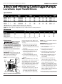
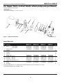
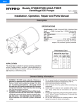
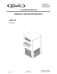
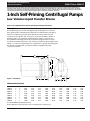
Specifications Information and
Repair Parts Manual
5660-97 thru 5669-97
Please read and save this Repair Parts Manual. Read this manual and the General Operating Instructions carefully before attempting to
assemble, install, operate or maintain the product described. Protect yourself and others by observing all safety information. The Safety
Instructions are contained in the General Operating Instructions. Failure to comply with the safety instructions accompanying this product
could result in personal injury and/or property damage! Retain instructions for future reference.
1-Inch Self-Priming Centrifugal Pumps
Low Volume Liquid Transfer Bronze
Refer to form 1808-634-00 for General Operating and Safety Instructions.
Description
These self-priming (to 6 ft. lift) centrifugal pumps are designed for continuous
duty, general purpose liquid transfer. Applications include livewell recirculation,
marine air conditioning, and salt water aquaculture. Pumps feature bronze
construction, Buna N seals, and a semi-open clog resistant impeller capable of
handling solids to 1/8" diameter. Handle liquids from 40º F to 180º F (4º C to
82º C). Maximum working pressure 75 psi (517 kPa). Single phase motors have
automatic reset thermal protection. All models are manual mode and require field
wiring, no controls are supplied (see motor nameplate for specific wiring diagram).
For use with nonflammable, non-abrasive liquids compatible with pump
component materials.
CP
Discharge
Y
Suction
S
X
D
Figure 1 - Dimensions
F
H
L
E
E
Dimensions (Inches)
Model
5660-97
5661-97
5662-97
5664-97
5665-97
5666-97
5667-97
5669-97
Suc.* Dis.*
CP†
D
E
F
H
L
S
X
Y
1"
1
1
1
1
1
1
1
14.11
14.61
15.11
16.09
15.53
16.03
16.41
17.66
3.50
3.50
3.50
3.50
3.50
3.50
3.50
3.50
2.25
2.25
2.25
2.25
2.25
2.25
2.25
2.25
3.00
3.00
3.00
3.00
3.00
3.00
3.00
3.00
0.44
0.44
0.44
0.44
0.44
0.44
0.44
0.44
4.28
4.28
4.28
4.28
4.28
4.28
4.28
4.28
4.00
4.00
4.00
4.00
4.00
4.00
4.00
4.00
5.25
5.25
5.25
5.25
5.25
5.25
5.25
5.25
3.94
3.94
3.94
3.94
3.94
3.94
3.94
3.94
1"
1
1
1
1
1
1
1
(*) Standard NPT (female) pipe thread.
(†) This dimension may vary due to motor manufacturer’s specifications.
5660-250-00
09/2002
Specifications Information and Repair Parts Manual
5660-97 thru 5669-97
1-Inch Self-Priming Centrifugal Pumps
Low Volume Liquid Transfer Bronze
Specifications
DRIVER
PUMP
Power
NEMA
Model
HP
Phase Enclosure Supply
Hertz
Frame
RPM
Casing
5660-97
1/2
1
ODP
115/230 VAC
60
56J
3450
BR
5661-97
3/4
1
ODP
115/230 VAC
60
56J
3450
BR
5662-97
1
1
ODP
115/230 VAC
60
56J
3450
BR
5664-97
2
1
ODP
115/230 VAC
60
56J
3450
BR
5665-97
1/2
1
TEFC
115/230 VAC
60
56J
3450
BR
5666-97
3/4
1
TEFC
115/230 VAC
60
56J
3450
BR
5667-97
1
1
TEFC
115/230 VAC
60
56J
3450
BR
5669-97
2
1
TEFC
115/230 VAC
60
56J
3450
BR
(ODP) Open Drip Proof; (TEFC) Totally Enclosed Fan Cooled; (BR) Bronze
(‡) Shaft seal also contains carbon, ceramic, and stainless steel components.
NOTE: Driver data is subject to change without notice, see label on driver for actual specifications.
Adapt.
BR
BR
BR
BR
BR
BR
BR
BR
Imp.
BR
BR
BR
BR
BR
BR
BR
BR
Ship
Weight
(Lbs.)
38
39
42
60
41
43
46
65
Seals‡
Buna N
Buna N
Buna N
Buna N
Buna N
Buna N
Buna N
Buna N
Performance
GPM of Water at Total Head in Feet
Model
HP
10'
20'
30'
5660-97, 5665-97
1/2
38
30
20
5661-97, 5666-97
3/4
56
48
37
5662-97, 5667-97
1
70
61
50
5664-97, 5669-97
2
90
83
74
(**) Shutoff; to convert to PSI, multiply by SG (specific gravity of liquid), then divide by 2.31.
Maintenance
Make certain that
power source is
disconnected before attempting to
service or disassemble any components!
If power disconnect is out-of-sight, lock
it in open position and tag it to prevent
application of power.
MECHANICAL SEAL REPLACEMENT
Refer to Figures 2 and 3.
IMPORTANT: Always replace both seal
seat (Ref. No. 9) and seal head (Ref. No.
10) to insure proper mating of
mechanical seal components!
NOTE: It is not necessary to remove
Adapter
Motor
shaft
Impeller
Seal seat
Seal head
piping from pump casing. Motor and
impeller assembly is removed from back
of casing.
1. Drain pump before disassembling
Unscrew pipe plug (Ref. No. 14) to
drain most of liquid; some will be left
in bottom.
2. Unthread fasteners (Ref. No. 5) and
remove pump casing (Ref. No. 13)
and casing seal (Ref. No. 8) from
casing cover (Ref. No. 7).
3. To unscrew impeller (Ref. No. 12),
turn counterclockwise (CCW) facing
impeller.
NOTE: A screwdriver slot or two flats
for use with an open end 7/16" wrench,
are provided at rear of motor shaft
(remove bearing cap for access). To hold
motor shaft from turning, either insert
a large screwdriver blade into slot, or
use a 7/16" wrench across flats.
4. Unthread fasteners (Ref. No. 6) and
remove motor adapter (Ref. No. 4).
Seal head and impeller shims (Ref.
No. 11) will come loose at this time.
Figure 2 - Mechanical Seal Replacement
2
40'
9
24
38
64
50'
—
7
24
50
60'
—
—
—
28
Max.
Head**
47 ft.
53
60
68
NOTE: Casing cover will still be attached
to motor adapter.
IMPORTANT: Retain impeller shims for
use when reassembling unit.
5. Push seal seat from casing cover
with screwdriver.
6. Clean adapter recess before
inserting a new seal seat.
7. Carefully wipe polished surface of
new seal seat with a clean cloth.
8. Wet outside of rubber portion of
seal seat with a light coating of
soapy water.
9. Press new seal seat squarely into
cavity in casing cover. If seal seat
does not press squarely into cavity, it
can be adjusted into place by
pushing on it carefully with a piece
of pipe or dowel. Always use a piece
of cardboard between pipe and seal
seat to avoid scratching seal seat.
(This is a lapped surface and must be
handled very carefully.)
10. After seal seat is in place, insure that
it is clean and has not been marred.
Specifications Information and Repair Parts Manual
Models 5660-97 thru 5669-97
Maintenance (Continued)
11. Using a clean cloth, wipe shaft and
make certain that it is perfectly
clean.
NOTE: If removed, slide slinger washer
(Ref. No. 2) onto shaft until it is
located approximately 1/8" from face
of motor bearing hub.
12. Carefully guide motor shaft
through seal seat. Secure motor
adapter on motor mounting face.
13. Apply a light coating of soapy
water to inside rubber portion of
seal head and slide onto shaft (with
sealing face first) so that rubber
portion is just up over shaft
shoulder.
Do not touch or
wipe face of
polished part of seal head.
14. Replace any impeller shims which
may have been removed in
disassembly (see “Shim
Adjustment”).
15. Screw impeller back in place,
tightening until it is against shaft
shoulder.
16. Remount casing seal and pump
casing on casing cover.
IMPORTANT: Always inspect casing
seal for cracks or cuts when unit is
disassembled. Replace if damaged.
SHIM ADJUSTMENT
When installing a replacement
impeller (Ref. No. 12) or motor (Ref.
No. 1), it may be necessary to adjust
number of shims (Ref. No. 11) to insure
proper running clearance between
impeller and casing (Ref. No. 13).
Proceed as follows:
NOTE: A proper running clearance is
less than 0.010".
1. For impeller replacement, add one
0.010" shim in addition to shims
removed originally.
2. For motor replacement, add two
0.010" shims in addition to shims
removed during disassembly.
3. Reassemble pump using
”Mechanical Seal Replacement” for
reference.
IMPORTANT: Insure that casing is in
place and check shaft to make sure it is
turning freely (use screwdriver slot or
two flats at rear of motor to turn
shaft). If it turns freely, check to insure
that casing cover and casing are fitted
“metal to metal” where they meet on
3
outside. If they are not “metal to
metal” tighten fasteners (Ref. No. 5)
and recheck shaft for free turning.
Tighten carefully turning shaft while
tightening so that motor bearings are
not damaged in event that too many
shims were installed. If shaft seizes
before fasteners are completely tight,
disassemble pump and remove one
shim and repeat reassembly.
5660-97 thru 5669-97
Specifications Information and Repair Parts Manual
For Repair Parts, contact dealer where pump was purchased.
Please provide following information:
-Model number
-Serial number (if any)
-Part description and number as shown in parts list
6
7
13
8
9
1
2
10
11
12
3
4
5
14
Figure 3 — Repair Parts Illustration
Repair Parts List
Ref.
No.
1
2
3
4
5
6
7
8
9
10
11
12
13
14
Description
Motor
-1 Phase ODP
-1 Phase TEFC
Slinger washer
Fastener
Adapter
Fastener
Fastener
Casing cover
Casing seal -Buna N
‡ Seal seat
-Buna N
‡ Seal head -Buna N
Impeller shim (package of 3)
Impeller
Casing
Pipe plug
Part Number For Models:
5660-97 (1/2HP)
5661-97 (3/4HP)
5665-97 (1/2HP)
5666-97 (3/4HP)
5662-97 (1HP)
5667-97 (1HP)
5664-97 (2HP)
5669-97 (2HP)
1626-009-00
1626-068-00
1534-000-00
*
1993-000-01
*
*
2104-003-02
2104-004-00
1640-161-90
1640-161-90
1657-000-90
2104-006-01
2218-006-01
*
1626-011-00
1626-069-00
1534-000-00
*
1993-000-01
*
*
2104-003-02
2104-004-00
1640-161-90
1640-161-90
1657-000-90
2104-002-01
2218-006-01
*
1626-024-00
1
1626-070-00
1534-000-00
1
*
4
1993-000-01
1
*
6
*
4
2104-003-02
1
2104-004-00
1
1640-161-90
1
1640-161-90
1
1657-000-90 1 pkg
2104-015-02
1
2218-006-01
1
*
1
1626-010-00
1626-051-00
1534-000-00
*
1993-000-01
*
*
2104-003-02
2104-004-00
1640-161-90
1640-161-90
1657-000-90
2104-006-02
2218-006-01
*
(‡) Seal Assembly (Ref. Nos. 9 & 10) includes Seal Head and Seal Seat and is available as a set only.
(*) Standard hardware item, available locally.
4
Qty.