1
HP Modular Cooling System
Maintenance and Service Guide
Part Number 403349-003
October 2008 (Third Edition)
© Copyright 2006, 2008 Hewlett-Packard Development Company, L.P.
The information contained herein is subject to change without notice. The only warranties for HP products and services are set forth in the express
warranty statements accompanying such products and services. Nothing herein should be construed as constituting an additional warranty. HP
shall not be liable for technical or editorial errors or omissions contained herein.
Intended audience
This guide is for an experienced service technician. HP assumes you are qualified in the servicing of
computer equipment and trained in recognizing hazards in products with hazardous energy levels and
are familiar with weight and stability precautions for rack installations.
Contents
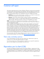
Customer self repair ...................................................................................................................... 6
Parts only warranty service ......................................................................................................................... 6
Illustrated parts catalog ............................................................................................................... 17
Replaceable spare parts........................................................................................................................... 17
Flow meter repair .................................................................................................................................... 20
Removal and replacement procedures ........................................................................................... 22
Removal and replacement procedure overview ........................................................................................... 22
Viewing the spare replacement video ........................................................................................................ 22
Customer self repair required tools ............................................................................................................ 22
Safety considerations ............................................................................................................................... 24
Rack warnings and cautions ........................................................................................................... 24
Preparation procedures ............................................................................................................................ 24
Powering down the MCS unit.......................................................................................................... 24
Shutting off the water ..................................................................................................................... 25
AC transfer switch ................................................................................................................................... 26
Removing the AC transfer switch ..................................................................................................... 26
Replacing the AC transfer switch ..................................................................................................... 28
Air bleeder valve..................................................................................................................................... 31
Removing the air bleeder valve ....................................................................................................... 31
Replacing the air bleeder valve ....................................................................................................... 32
Air deflector plate ................................................................................................................................... 33
Removing the air deflector plate ...................................................................................................... 33
Replacing the air deflector plate ...................................................................................................... 34
Air sealing plate...................................................................................................................................... 34
Removing the air sealing plate ........................................................................................................ 35
Replacing the air sealing plate ........................................................................................................ 36
Automatic door release ............................................................................................................................ 38
Removing the front automatic door release........................................................................................ 38
Replacing the front automatic door release ....................................................................................... 39
Removing the rear automatic door release ........................................................................................ 41
Replacing the rear automatic door release ........................................................................................ 42
Bottom fan unit........................................................................................................................................ 44
Removing the bottom fan unit .......................................................................................................... 44
Replacing the bottom fan unit .......................................................................................................... 45
Condensation pump and sensors............................................................................................................... 47
Removing the condensation pump and sensors .................................................................................. 47
Replacing the condensation pump and sensors.................................................................................. 49
Fan unit ................................................................................................................................................. 50
Removing the fan unit..................................................................................................................... 51
Replacing the fan unit .................................................................................................................... 52
Flow meter sensor ................................................................................................................................... 54
Removing the flow meter paddle-wheel sensor................................................................................... 54
Replacing the flow meter paddle-wheel sensor................................................................................... 57
Heat exchanger unit (HEX) with coupler ..................................................................................................... 59
Removing the heat exchanger unit with couplers ................................................................................ 59
Contents
3
Replacing the heat exchanger unit with couplers................................................................................ 63
Heat exchanger unit (HEX) with ball valve .................................................................................................. 67
Removing the heat exchanger unit with ball valves............................................................................. 68
Replacing the heat exchanger unit with ball valves............................................................................. 72
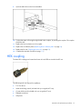
HEX coupling.......................................................................................................................................... 77
Removing the HEX coupling ............................................................................................................ 78
Replacing the HEX coupling ............................................................................................................ 80
Magnetic solenoid valve .......................................................................................................................... 82
Removing the magnetic solenoid valve ............................................................................................. 82
Replacing the magnetic solenoid valve ............................................................................................. 84
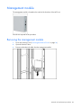
Management module ............................................................................................................................... 85
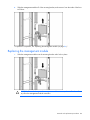
Removing the management module.................................................................................................. 85
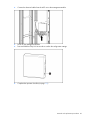
Replacing the management module ................................................................................................. 86
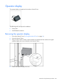
Operator display..................................................................................................................................... 88
Removing the operator display ........................................................................................................ 88
Replacing the operator display........................................................................................................ 91
Power inlet box ....................................................................................................................................... 93
Relocating the power inlet box ........................................................................................................ 93
Relocating the power inlet box back into position .............................................................................. 95
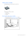
Water group controller ............................................................................................................................ 97
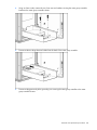
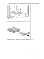
Removing the water group controller ................................................................................................ 97
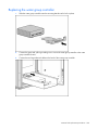
Replacing the water group controller.............................................................................................. 100
Water inlet coupling .............................................................................................................................. 102
Removing the water inlet coupling ................................................................................................. 102
Replacing the water inlet coupling ................................................................................................. 105
Water temperature sensor ...................................................................................................................... 107
Removing the water temperature sensor.......................................................................................... 107
Replacing the water temperature sensor ......................................................................................... 109
Operation checklist................................................................................................................................ 111
Restoring power to the MCS unit ................................................................................................... 111
Restoring water flow .................................................................................................................... 112
Technician repair removal and replacement procedures ................................................................ 113
Miscellaneous hardware kit overview....................................................................................................... 113
Technician repair required tools .................................................................................................... 114
Flow meter ........................................................................................................................................... 114
Removing the flow meter .............................................................................................................. 114
Replacing the flow meter .............................................................................................................. 117
Magnetic valve ..................................................................................................................................... 118
Removing the magnetic valve diaphragm and spring ....................................................................... 118
Replacing the magnetic valve diaphragm and spring ....................................................................... 120
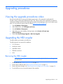
Upgrading procedures .............................................................................................................. 123
Viewing the upgrade procedures video .................................................................................................... 123
Upgrading the HEX coupler .................................................................................................................... 123
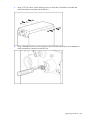
Removing the HEX coupler............................................................................................................ 123
Replacing the HEX coupler............................................................................................................ 128
Upgrading the HEX hose coupler............................................................................................................. 132
Removing the HEX hose coupler .................................................................................................... 132
Replacing the HEX hose coupler .................................................................................................... 132
Maintenance ............................................................................................................................ 139
Maintenance and service ....................................................................................................................... 139
Air and water heat exchanger maintenance.................................................................................... 139
Contents
4
Water quality.............................................................................................................................. 139
Condensation management .......................................................................................................... 139
Frost damage.............................................................................................................................. 139
Diagnostic tools .................................................................................................................................... 140
Troubleshooting ........................................................................................................................ 141
HP Modular Cooling System troubleshooting............................................................................................. 141
Specifications ........................................................................................................................... 142
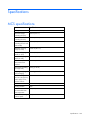
MCS specifications................................................................................................................................ 142
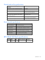
Thermal and air flow performance ................................................................................................. 143
Environmental specifications ......................................................................................................... 143
HP 10642 G2 Rack specifications........................................................................................................... 143
Acronyms and abbreviations...................................................................................................... 144
Index....................................................................................................................................... 145
Contents
5
Customer self repair
HP products are designed with many Customer Self Repair (CSR) parts to minimize repair time and allow
for greater flexibility in performing defective parts replacement. If during the diagnosis period HP (or HP
service providers or service partners) identifies that the repair can be accomplished by the use of a CSR
part, HP will ship that part directly to you for replacement. There are two categories of CSR parts:
•
Mandatory—Parts for which customer self repair is mandatory. If you request HP to replace these
parts, you will be charged for the travel and labor costs of this service.
•
Optional—Parts for which customer self repair is optional. These parts are also designed for
customer self repair. If, however, you require that HP replace them for you, there may or may not be
additional charges, depending on the type of warranty service designated for your product.
NOTE: Some HP parts are not designed for customer self repair. In order to satisfy the customer
warranty, HP requires that an authorized service provider replace the part. These parts are identified as
"No" in the Illustrated Parts Catalog.
Based on availability and where geography permits, CSR parts will be shipped for next business day
delivery. Same day or four-hour delivery may be offered at an additional charge where geography
permits. If assistance is required, you can call the HP Technical Support Center and a technician will help
you over the telephone. HP specifies in the materials shipped with a replacement CSR part whether a
defective part must be returned to HP. In cases where it is required to return the defective part to HP, you
must ship the defective part back to HP within a defined period of time, normally five (5) business days.
The defective part must be returned with the associated documentation in the provided shipping material.
Failure to return the defective part may result in HP billing you for the replacement. With a customer self
repair, HP will pay all shipping and part return costs and determine the courier/carrier to be used.
For more information about HP's Customer Self Repair program, contact your local service provider. For
the North American program, refer to the HP website (http://www.hp.com/go/selfrepair).
Parts only warranty service
Your HP Limited Warranty may include a parts only warranty service. Under the terms of parts only
warranty service, HP will provide replacement parts free of charge.
For parts only warranty service, CSR part replacement is mandatory. If you request HP to replace these
parts, you will be charged for the travel and labor costs of this service.
Réparation par le client (CSR)
Les produits HP comportent de nombreuses pièces CSR (Customer Self Repair = réparation par le client)
afin de minimiser les délais de réparation et faciliter le remplacement des pièces défectueuses. Si pendant
la période de diagnostic, HP (ou ses partenaires ou mainteneurs agréés) détermine que la réparation peut
être effectuée à l'aide d'une pièce CSR, HP vous l'envoie directement. Il existe deux catégories de pièces
CSR:
Customer self repair 6
•
Obligatoire - Pièces pour lesquelles la réparation par le client est obligatoire. Si vous demandez à
HP de remplacer ces pièces, les coûts de déplacement et main d'œuvre du service vous seront
facturés.
•
Facultatif - Pièces pour lesquelles la réparation par le client est facultative. Ces pièces sont
également conçues pour permettre au client d'effectuer lui-même la réparation. Toutefois, si vous
demandez à HP de remplacer ces pièces, l'intervention peut ou non vous être facturée, selon le type
de garantie applicable à votre produit.
REMARQUE: Certaines pièces HP ne sont pas conçues pour permettre au client d'effectuer lui-même la
réparation. Pour que la garantie puisse s'appliquer, HP exige que le remplacement de la pièce soit
effectué par un Mainteneur Agréé. Ces pièces sont identifiées par la mention "Non" dans le Catalogue
illustré.
Les pièces CSR sont livrées le jour ouvré suivant, dans la limite des stocks disponibles et selon votre
situation géographique. Si votre situation géographique le permet et que vous demandez une livraison le
jour même ou dans les 4 heures, celle-ci vous sera facturée. Pour bénéficier d'une assistance
téléphonique, appelez le Centre d'assistance technique HP. Dans les documents envoyés avec la pièce de
rechange CSR, HP précise s'il est nécessaire de lui retourner la pièce défectueuse. Si c'est le cas, vous
devez le faire dans le délai indiqué, généralement cinq (5) jours ouvrés. La pièce et sa documentation
doivent être retournées dans l'emballage fourni. Si vous ne retournez pas la pièce défectueuse, HP se
réserve le droit de vous facturer les coûts de remplacement. Dans le cas d'une pièce CSR, HP supporte
l'ensemble des frais d'expédition et de retour, et détermine la société de courses ou le transporteur à
utiliser.
Pour plus d'informations sur le programme CSR de HP, contactez votre Mainteneur Agrée local. Pour plus
d'informations sur ce programme en Amérique du Nord, consultez le site Web HP
(http://www.hp.com/go/selfrepair).
Service de garantie "pièces seules"
Votre garantie limitée HP peut inclure un service de garantie "pièces seules". Dans ce cas, les pièces de
rechange fournies par HP ne sont pas facturées.
Dans le cadre de ce service, la réparation des pièces CSR par le client est obligatoire. Si vous demandez
à HP de remplacer ces pièces, les coûts de déplacement et main d'œuvre du service vous seront facturés.
Riparazione da parte del cliente
Per abbreviare i tempi di riparazione e garantire una maggiore flessibilità nella sostituzione di parti
difettose, i prodotti HP sono realizzati con numerosi componenti che possono essere riparati direttamente
dal cliente (CSR, Customer Self Repair). Se in fase di diagnostica HP (o un centro di servizi o di
assistenza HP) identifica il guasto come riparabile mediante un ricambio CSR, HP lo spedirà direttamente
al cliente per la sostituzione. Vi sono due categorie di parti CSR:
•
Obbligatorie – Parti che devono essere necessariamente riparate dal cliente. Se il cliente ne affida
la riparazione ad HP, deve sostenere le spese di spedizione e di manodopera per il servizio.
•
Opzionali – Parti la cui riparazione da parte del cliente è facoltativa. Si tratta comunque di
componenti progettati per questo scopo. Se tuttavia il cliente ne richiede la sostituzione ad HP,
potrebbe dover sostenere spese addizionali a seconda del tipo di garanzia previsto per il prodotto.
Customer self repair 7
NOTA: alcuni componenti HP non sono progettati per la riparazione da parte del cliente. Per rispettare
la garanzia, HP richiede che queste parti siano sostituite da un centro di assistenza autorizzato. Tali parti
sono identificate da un "No" nel Catalogo illustrato dei componenti.
In base alla disponibilità e alla località geografica, le parti CSR vengono spedite con consegna entro il
giorno lavorativo seguente. La consegna nel giorno stesso o entro quattro ore è offerta con un
supplemento di costo solo in alcune zone. In caso di necessità si può richiedere l'assistenza telefonica di
un addetto del centro di supporto tecnico HP. Nel materiale fornito con una parte di ricambio CSR, HP
specifica se il cliente deve restituire dei componenti. Qualora sia richiesta la resa ad HP del componente
difettoso, lo si deve spedire ad HP entro un determinato periodo di tempo, generalmente cinque (5) giorni
lavorativi. Il componente difettoso deve essere restituito con la documentazione associata nell'imballo di
spedizione fornito. La mancata restituzione del componente può comportare la fatturazione del ricambio
da parte di HP. Nel caso di riparazione da parte del cliente, HP sostiene tutte le spese di spedizione e
resa e sceglie il corriere/vettore da utilizzare.
Per ulteriori informazioni sul programma CSR di HP contattare il centro di assistenza di zona. Per il
programma in Nord America fare riferimento al sito Web HP (http://www.hp.com/go/selfrepair).
Servizio di garanzia per i soli componenti
La garanzia limitata HP può includere un servizio di garanzia per i soli componenti. Nei termini di
garanzia del servizio per i soli componenti, HP fornirà gratuitamente le parti di ricambio.
Per il servizio di garanzia per i soli componenti è obbligatoria la formula CSR che prevede la riparazione
da parte del cliente. Se il cliente invece richiede la sostituzione ad HP, dovrà sostenere le spese di
spedizione e di manodopera per il servizio.
Customer Self Repair
HP Produkte enthalten viele CSR-Teile (Customer Self Repair), um Reparaturzeiten zu minimieren und
höhere Flexibilität beim Austausch defekter Bauteile zu ermöglichen. Wenn HP (oder ein HP
Servicepartner) bei der Diagnose feststellt, dass das Produkt mithilfe eines CSR-Teils repariert werden
kann, sendet Ihnen HP dieses Bauteil zum Austausch direkt zu. CSR-Teile werden in zwei Kategorien
unterteilt:
•
Zwingend – Teile, für die das Customer Self Repair-Verfahren zwingend vorgegeben ist. Wenn Sie
den Austausch dieser Teile von HP vornehmen lassen, werden Ihnen die Anfahrt- und Arbeitskosten
für diesen Service berechnet.
•
Optional – Teile, für die das Customer Self Repair-Verfahren optional ist. Diese Teile sind auch für
Customer Self Repair ausgelegt. Wenn Sie jedoch den Austausch dieser Teile von HP vornehmen
lassen möchten, können bei diesem Service je nach den für Ihr Produkt vorgesehenen
Garantiebedingungen zusätzliche Kosten anfallen.
HINWEIS: Einige Teile sind nicht für Customer Self Repair ausgelegt. Um den Garantieanspruch des
Kunden zu erfüllen, muss das Teil von einem HP Servicepartner ersetzt werden. Im illustrierten Teilekatalog
sind diese Teile mit „No“ bzw. „Nein“ gekennzeichnet.
CSR-Teile werden abhängig von der Verfügbarkeit und vom Lieferziel am folgenden Geschäftstag
geliefert. Für bestimmte Standorte ist eine Lieferung am selben Tag oder innerhalb von vier Stunden gegen
einen Aufpreis verfügbar. Wenn Sie Hilfe benötigen, können Sie das HP technische Support Center
Customer self repair 8
anrufen und sich von einem Mitarbeiter per Telefon helfen lassen. Den Materialien, die mit einem CSRErsatzteil geliefert werden, können Sie entnehmen, ob das defekte Teil an HP zurückgeschickt werden
muss. Wenn es erforderlich ist, das defekte Teil an HP zurückzuschicken, müssen Sie dies innerhalb eines
vorgegebenen Zeitraums tun, in der Regel innerhalb von fünf (5) Geschäftstagen. Das defekte Teil muss
mit der zugehörigen Dokumentation in der Verpackung zurückgeschickt werden, die im Lieferumfang
enthalten ist. Wenn Sie das defekte Teil nicht zurückschicken, kann HP Ihnen das Ersatzteil in Rechnung
stellen. Im Falle von Customer Self Repair kommt HP für alle Kosten für die Lieferung und Rücksendung auf
und bestimmt den Kurier-/Frachtdienst.
Weitere Informationen über das HP Customer Self Repair Programm erhalten Sie von Ihrem Servicepartner
vor Ort. Informationen über das CSR-Programm in Nordamerika finden Sie auf der HP Website unter
(http://www.hp.com/go/selfrepair).
Parts-only Warranty Service (Garantieservice
ausschließlich für Teile)
Ihre HP Garantie umfasst möglicherweise einen Parts-only Warranty Service (Garantieservice
ausschließlich für Teile). Gemäß den Bestimmungen des Parts-only Warranty Service stellt HP Ersatzteile
kostenlos zur Verfügung.
Für den Parts-only Warranty Service ist das CSR-Verfahren zwingend vorgegeben. Wenn Sie den
Austausch dieser Teile von HP vornehmen lassen, werden Ihnen die Anfahrt- und Arbeitskosten für diesen
Service berechnet.
Reparaciones del propio cliente
Los productos de HP incluyen muchos componentes que el propio usuario puede reemplazar (Customer
Self Repair, CSR) para minimizar el tiempo de reparación y ofrecer una mayor flexibilidad a la hora de
realizar sustituciones de componentes defectuosos. Si, durante la fase de diagnóstico, HP (o los
proveedores o socios de servicio de HP) identifica que una reparación puede llevarse a cabo mediante el
uso de un componente CSR, HP le enviará dicho componente directamente para que realice su
sustitución. Los componentes CSR se clasifican en dos categorías:
•
Obligatorio: componentes para los que la reparación por parte del usuario es obligatoria. Si
solicita a HP que realice la sustitución de estos componentes, tendrá que hacerse cargo de los
gastos de desplazamiento y de mano de obra de dicho servicio.
•
Opcional: componentes para los que la reparación por parte del usuario es opcional. Estos
componentes también están diseñados para que puedan ser reparados por el usuario. Sin embargo,
si precisa que HP realice su sustitución, puede o no conllevar costes adicionales, dependiendo del
tipo de servicio de garantía correspondiente al producto.
NOTA: Algunos componentes no están diseñados para que puedan ser reparados por el usuario. Para
que el usuario haga valer su garantía, HP pone como condición que un proveedor de servicios
autorizado realice la sustitución de estos componentes. Dichos componentes se identifican con la palabra
"No" en el catálogo ilustrado de componentes.
Según la disponibilidad y la situación geográfica, los componentes CSR se enviarán para que lleguen a
su destino al siguiente día laborable. Si la situación geográfica lo permite, se puede solicitar la entrega
en el mismo día o en cuatro horas con un coste adicional. Si precisa asistencia técnica, puede llamar al
Customer self repair 9
Centro de asistencia técnica de HP y recibirá ayuda telefónica por parte de un técnico. Con el envío de
materiales para la sustitución de componentes CSR, HP especificará si los componentes defectuosos
deberán devolverse a HP. En aquellos casos en los que sea necesario devolver algún componente a HP,
deberá hacerlo en el periodo de tiempo especificado, normalmente cinco días laborables. Los
componentes defectuosos deberán devolverse con toda la documentación relacionada y con el embalaje
de envío. Si no enviara el componente defectuoso requerido, HP podrá cobrarle por el de sustitución. En
el caso de todas sustituciones que lleve a cabo el cliente, HP se hará cargo de todos los gastos de envío
y devolución de componentes y escogerá la empresa de transporte que se utilice para dicho servicio.
Para obtener más información acerca del programa de Reparaciones del propio cliente de HP, póngase
en contacto con su proveedor de servicios local. Si está interesado en el programa para Norteamérica,
visite la página web de HP siguiente (http://www.hp.com/go/selfrepair).
Servicio de garantía exclusivo de componentes
La garantía limitada de HP puede que incluya un servicio de garantía exclusivo de componentes. Según
las condiciones de este servicio exclusivo de componentes, HP le facilitará los componentes de repuesto
sin cargo adicional alguno.
Para este servicio de garantía exclusivo de componentes, es obligatoria la sustitución de componentes
por parte del usuario (CSR). Si solicita a HP que realice la sustitución de estos componentes, tendrá que
hacerse cargo de los gastos de desplazamiento y de mano de obra de dicho servicio.
Customer Self Repair
Veel onderdelen in HP producten zijn door de klant zelf te repareren, waardoor de reparatieduur tot een
minimum beperkt kan blijven en de flexibiliteit in het vervangen van defecte onderdelen groter is. Deze
onderdelen worden CSR-onderdelen (Customer Self Repair) genoemd. Als HP (of een HP Service Partner)
bij de diagnose vaststelt dat de reparatie kan worden uitgevoerd met een CSR-onderdeel, verzendt HP
dat onderdeel rechtstreeks naar u, zodat u het defecte onderdeel daarmee kunt vervangen. Er zijn twee
categorieën CSR-onderdelen:
•
Verplicht: Onderdelen waarvoor reparatie door de klant verplicht is. Als u HP verzoekt deze
onderdelen voor u te vervangen, worden u voor deze service reiskosten en arbeidsloon in rekening
gebracht.
•
Optioneel: Onderdelen waarvoor reparatie door de klant optioneel is. Ook deze onderdelen zijn
ontworpen voor reparatie door de klant. Als u echter HP verzoekt deze onderdelen voor u te
vervangen, kunnen daarvoor extra kosten in rekening worden gebracht, afhankelijk van het type
garantieservice voor het product.
OPMERKING: Sommige HP onderdelen zijn niet ontwikkeld voor reparatie door de klant. In verband
met de garantievoorwaarden moet het onderdeel door een geautoriseerde Service Partner worden
vervangen. Deze onderdelen worden in de geïllustreerde onderdelencatalogus aangemerkt met "Nee".
Afhankelijk van de leverbaarheid en de locatie worden CSR-onderdelen verzonden voor levering op de
eerstvolgende werkdag. Levering op dezelfde dag of binnen vier uur kan tegen meerkosten worden
aangeboden, indien dit mogelijk is gezien de locatie. Indien assistentie gewenst is, belt u een HP Service
Partner om via de telefoon technische ondersteuning te ontvangen. HP vermeldt in de documentatie bij het
vervangende CSR-onderdeel of het defecte onderdeel aan HP moet worden geretourneerd. Als het defecte
onderdeel aan HP moet worden teruggezonden, moet u het defecte onderdeel binnen een bepaalde
Customer self repair 10
periode, gewoonlijk vijf (5) werkdagen, retourneren aan HP. Het defecte onderdeel moet met de
bijbehorende documentatie worden geretourneerd in het meegeleverde verpakkingsmateriaal. Als u het
defecte onderdeel niet terugzendt, kan HP u voor het vervangende onderdeel kosten in rekening brengen.
Bij reparatie door de klant betaalt HP alle verzendkosten voor het vervangende en geretourneerde
onderdeel en kiest HP zelf welke koerier/transportonderneming hiervoor wordt gebruikt.
Neem contact op met een Service Partner voor meer informatie over het Customer Self Repair programma
van HP. Informatie over Service Partners vindt u op de HP website (http://www.hp.com/go/selfrepair).
Garantieservice "Parts Only"
Het is mogelijk dat de HP garantie alleen de garantieservice "Parts Only" omvat. Volgens de bepalingen
van de Parts Only garantieservice zal HP kosteloos vervangende onderdelen ter beschikking stellen.
Voor de Parts Only garantieservice is vervanging door CSR-onderdelen verplicht. Als u HP verzoekt deze
onderdelen voor u te vervangen, worden u voor deze service reiskosten en arbeidsloon in rekening
gebracht.
Reparo feito pelo cliente
Os produtos da HP são projetados com muitas peças para reparo feito pelo cliente (CSR) de modo a
minimizar o tempo de reparo e permitir maior flexibilidade na substituição de peças com defeito. Se,
durante o período de diagnóstico, a HP (ou fornecedores/parceiros de serviço da HP) concluir que o
reparo pode ser efetuado pelo uso de uma peça CSR, a peça de reposição será enviada diretamente ao
cliente. Existem duas categorias de peças CSR:
•
Obrigatória – Peças cujo reparo feito pelo cliente é obrigatório. Se desejar que a HP substitua
essas peças, serão cobradas as despesas de transporte e mão-de-obra do serviço.
•
Opcional – Peças cujo reparo feito pelo cliente é opcional. Essas peças também são projetadas
para o reparo feito pelo cliente. No entanto, se desejar que a HP as substitua, pode haver ou não a
cobrança de taxa adicional, dependendo do tipo de serviço de garantia destinado ao produto.
OBSERVAÇÃO: Algumas peças da HP não são projetadas para o reparo feito pelo cliente. A fim de
cumprir a garantia do cliente, a HP exige que um técnico autorizado substitua a peça. Essas peças estão
identificadas com a marca "No" (Não), no catálogo de peças ilustrado.
Conforme a disponibilidade e o local geográfico, as peças CSR serão enviadas no primeiro dia útil após
o pedido. Onde as condições geográficas permitirem, a entrega no mesmo dia ou em quatro horas pode
ser feita mediante uma taxa adicional. Se precisar de auxílio, entre em contato com o Centro de suporte
técnico da HP para que um técnico o ajude por telefone. A HP especifica nos materiais fornecidos com a
peça CSR de reposição se a peça com defeito deve ser devolvida à HP. Nos casos em que isso for
necessário, é preciso enviar a peça com defeito à HP dentro do período determinado, normalmente
cinco (5) dias úteis. A peça com defeito deve ser enviada com a documentação correspondente no
material de transporte fornecido. Caso não o faça, a HP poderá cobrar a reposição. Para as peças de
reparo feito pelo cliente, a HP paga todas as despesas de transporte e de devolução da peça e
determina a transportadora/serviço postal a ser utilizado.
Para obter mais informações sobre o programa de reparo feito pelo cliente da HP, entre em contato com
o fornecedor de serviços local. Para o programa norte-americano, visite o site da HP
(http://www.hp.com/go/selfrepair).
Customer self repair 11
Serviço de garantia apenas para peças
A garantia limitada da HP pode incluir um serviço de garantia apenas para peças. Segundo os termos
do serviço de garantia apenas para peças, a HP fornece as peças de reposição sem cobrar nenhuma
taxa.
No caso desse serviço, a substituição de peças CSR é obrigatória. Se desejar que a HP substitua essas
peças, serão cobradas as despesas de transporte e mão-de-obra do serviço.
Customer self repair 12
Customer self repair 13
Customer self repair 14
Customer self repair 15
Customer self repair 16
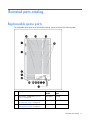
Illustrated parts catalog
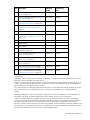
Replaceable spare parts
The replaceable spare parts for the HP Modular Cooling System are listed in the following table.
Item Description
Spare part
number
Customer self
repair
1
SPS–DISPLAY, OPERATOR ("Operator
display" on page 88)
395774-001
Optional2
2
SPS–HEAT EXCHANGER ("Heat exchanger
unit (HEX) with coupler" on page 59)
395776-001
Optional2
3
SPS–MCS, MGMT, MODULE
("Management module" on page 85)
395772-001
Optional2
Illustrated parts catalog 17
Item Description
Spare part
number
Customer self
repair
4
SPS–TRANSFER SWITCH ("AC transfer
switch" on page 26)
395773-001
Optional2
5
SPS–CONTROLLER, WATER ("Water group
controller" on page 97)
395771-001
Optional2
6
SPS–SOLENOID, MAGNETIC VALVE
("Magnetic solenoid valve" on page 82)
399037-001
Optional2
7
SPS–CONDENSATE, PUMP & SENSORS
("Condensation pump and sensors" on
page 47)
395775-001
Optional2
8
SPS–FAN, MAIN ("Fan unit" on page 50)
395777-001
Optional2
9
SPS–HARDWARE KIT, MISC
("Miscellaneous hardware kit overview" on
page 113)
407165-001
No3
9A) Magnetic valve diaphragm and spring
—
—
9B) Flow meter
—
—
9C) Gasket*
—
—
10
SPS–COUPLING, MCS, HEX ("HEX
coupling" on page 77)
444000-001
Optional2
11
SPS–COUPLING, MCS, INLET ("Water inlet
coupling" on page 102)
444001-001
Optional2
12
SPS–KIT, FLOW METER, REPAIR ("Flow
meter sensor" on page 54)
441821-001
Optional2
13
SPS–VALVE, AIR BLEEDER ("Air bleeder
valve" on page 31)
446971-001
Optional2
14
SPS–SENSORS, TEMP, INLET/OUTLET
("Water temperature sensor" on page 107)
446970-001
Optional2
**
SPS–KIT, DOOR RELEASE, AUTOMATIC
("Automatic door release" on page 38)
441822-001
Optional2
* Removal and replacement instructions are not included in this document.
** Not shown
1
Mandatory—Parts for which customer self repair is mandatory. If you request HP to replace these parts, you will be
charged for the travel and labor costs of this service.
2
Optional—Parts for which customer self repair is optional. These parts are also designed for customer self repair. If,
however, you require that HP replace them for you, there may or may not be additional charges, depending on the
type of warranty service designated for your product.
3
No—Some HP parts are not designed for customer self repair. In order to satisfy the customer warranty, HP requires
that an authorized service provider replace the part. These parts are identified as "No" in the Illustrated Parts
Catalog.
Mandatory: Obligatoire—Pièces pour lesquelles la réparation par le client est obligatoire. Si vous demandez à HP
de remplacer ces pièces, les coûts de déplacement et main d'œuvre du service vous seront facturés.
2
Optional: Facultatif—Pièces pour lesquelles la réparation par le client est facultative. Ces pièces sont également
conçues pour permettre au client d'effectuer lui-même la réparation. Toutefois, si vous demandez à HP de remplacer
ces pièces, l'intervention peut ou non vous être facturée, selon le type de garantie applicable à votre produit.
3
No: Non—Certaines pièces HP ne sont pas conçues pour permettre au client d'effectuer lui-même la réparation. Pour
que la garantie puisse s'appliquer, HP exige que le remplacement de la pièce soit effectué par un Mainteneur Agréé.
Ces pièces sont identifiées par la mention “Non” dans le Catalogue illustré.
1
Illustrated parts catalog 18
Mandatory: Obbligatorie—Parti che devono essere necessariamente riparate dal cliente. Se il cliente ne affida la
riparazione ad HP, deve sostenere le spese di spedizione e di manodopera per il servizio.
2
Optional: Opzionali—Parti la cui riparazione da parte del cliente è facoltativa. Si tratta comunque di componenti
progettati per questo scopo. Se tuttavia il cliente ne richiede la sostituzione ad HP, potrebbe dover sostenere spese
addizionali a seconda del tipo di garanzia previsto per il prodotto.
3
No: Non CSR—Alcuni componenti HP non sono progettati per la riparazione da parte del cliente. Per rispettare la
garanzia, HP richiede che queste parti siano sostituite da un centro di assistenza autorizzato. Tali parti sono
identificate da un “No” nel Catalogo illustrato dei componenti.
1
1
Mandatory: Zwingend—Teile, die im Rahmen des Customer Self Repair Programms ersetzt werden müssen. Wenn
Sie diese Teile von HP ersetzen lassen, werden Ihnen die Versand- und Arbeitskosten für diesen Service berechnet.
2
Optional: Optional—Teile, für die das Customer Self Repair-Verfahren optional ist. Diese Teile sind auch für
Customer Self Repair ausgelegt. Wenn Sie jedoch den Austausch dieser Teile von HP vornehmen lassen möchten,
können bei diesem Service je nach den für Ihr Produkt vorgesehenen Garantiebedingungen zusätzliche Kosten
anfallen.
3
No: Kein—Einige Teile sind nicht für Customer Self Repair ausgelegt. Um den Garantieanspruch des Kunden zu
erfüllen, muss das Teil von einem HP Servicepartner ersetzt werden. Im illustrierten Teilekatalog sind diese Teile mit
„No“ bzw. „Nein“ gekennzeichnet.
Mandatory: Obligatorio—componentes para los que la reparación por parte del usuario es obligatoria. Si solicita a
HP que realice la sustitución de estos componentes, tendrá que hacerse cargo de los gastos de desplazamiento y de
mano de obra de dicho servicio.
2
Optional: Opcional— componentes para los que la reparación por parte del usuario es opcional. Estos
componentes también están diseñados para que puedan ser reparados por el usuario. Sin embargo, si precisa que
HP realice su sustitución, puede o no conllevar costes adicionales, dependiendo del tipo de servicio de garantía
correspondiente al producto.
3
No: No—Algunos componentes no están diseñados para que puedan ser reparados por el usuario. Para que el
usuario haga valer su garantía, HP pone como condición que un proveedor de servicios autorizado realice la
sustitución de estos componentes. Dichos componentes se identifican con la palabra “No” en el catálogo ilustrado de
componentes.
1
Mandatory: Verplicht—Onderdelen waarvoor Customer Self Repair verplicht is. Als u HP verzoekt deze onderdelen
te vervangen, komen de reiskosten en het arbeidsloon voor uw rekening.
2
Optional: Optioneel—Onderdelen waarvoor reparatie door de klant optioneel is. Ook deze onderdelen zijn
ontworpen voor reparatie door de klant. Als u echter HP verzoekt deze onderdelen voor u te vervangen, kunnen
daarvoor extra kosten in rekening worden gebracht, afhankelijk van het type garantieservice voor het product.
3
No: Nee—Sommige HP onderdelen zijn niet ontwikkeld voor reparatie door de klant. In verband met de
garantievoorwaarden moet het onderdeel door een geautoriseerde Service Partner worden vervangen. Deze
onderdelen worden in de geïllustreerde onderdelencatalogus aangemerkt met "Nee".
1
Mandatory: Obrigatória—Peças cujo reparo feito pelo cliente é obrigatório. Se desejar que a HP substitua essas
peças, serão cobradas as despesas de transporte e mão-de-obra do serviço.
2
Optional: Opcional—Peças cujo reparo feito pelo cliente é opcional. Essas peças também são projetadas para o
reparo feito pelo cliente. No entanto, se desejar que a HP as substitua, pode haver ou não a cobrança de taxa
adicional, dependendo do tipo de serviço de garantia destinado ao produto.
3
No: Nenhuma—Algumas peças da HP não são projetadas para o reparo feito pelo cliente. A fim de cumprir a
garantia do cliente, a HP exige que um técnico autorizado substitua a peça. Essas peças estão identificadas com a
marca “No” (Não), no catálogo de peças ilustrado.
1
Illustrated parts catalog 19
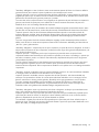
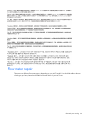
Flow meter repair
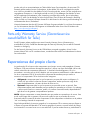
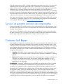
There are two different flow meter types, depending on your MCS model. You should be able to discern
which type you have, based on the label on the rear door of your MCS unit.
Illustrated parts catalog 20
The Type 1 flow meter has a round body, and is no longer used in current MCS models.
The Type 2 flow meter has a square body and ships installed in all current MCS models.
There are two scenarios when repairing your flow meter:
•
You currently have a Type 1 flow meter that you will remove and replace with a Type 2 flow meter.
For this type of repair, you will order the Miscellaneous Hardware Kit and have a trained technician
complete your repair.
-or-
•
You have a Type 2 flow meter and will remove and replace the flow meter paddle-wheel sensor at
the top of your flow meter. For this type of repair, you will order the Flow Meter Paddle-Wheel
Sensor Kit and can complete the repair yourself.
Illustrated parts catalog 21
Removal and replacement procedures
Removal and replacement procedure overview
This section provides guidance for removing and replacing the HP Modular Cooling System (MCS) spare
parts.
Follow the instructions carefully to ensure proper installation of the new spare part.
IMPORTANT: As you are removing the HP Modular Cooling System components, be sure to
retain the screws in a safe place and separate them according to their type.
Viewing the spare replacement video
Because of the difficulty of removing and replacing spare parts, HP recommends watching the HP
Modular Cooling System Spare Replacement video. This video provides further explanation and detail of
replacement strategies and techniques that might be helpful when attempting to remove and replace spare
parts. You can access the video on the HP website (http://www.hp.com/go/mcs).
1.
Select HP Modular Cooling System.
2.
Under Related Links, select HP Support and Drivers.
3.
Select HP Modular Cooling System.
4.
Under Resources for Modular Cooling System, select Customer self repair steps (videos/animations).
5.
Select Remove/Replace Videos.
6.
Select the appropriate spare part from the list on the left-hand side.
Customer self repair required tools
The following tools are required for each spares kit removal and replacement procedures:
•
•
•
AC transfer switch
o
T-25 Torx driver
o
Small Flathead screwdriver
Air bleeder valve
o
T-25 Torx driver
o
Pliers
o
Water hose fitting wrench (included with your original MCS unit)
o
Counter hold wrench (included with your original MCS unit)
Automatic door release
o
3-mm Allen wrench
Removal and replacement procedures 22
•
•
o
T-25 Torx driver
o
Wire cutters
Condensation pump and sensors
o
T-25 Torx driver
o
Phillips screwdriver
Fan unit
o
•
•
•
•
•
•
T-25 Torx driver
Flow meter paddle-wheel sensor
o
T-25 Torx driver
o
Wire cutters
o
Water hose fitting wrench (included with your original MCS unit)
o
Counter hold wrench (included with your original MCS unit)
Heat exchanger unit (HEX) with coupler
o
T-25 Torx driver
o
Water hose fitting wrench (included with your original MCS unit)
o
Counter hold wrench (included with your original MCS unit)
Heat exchanger unit (HEX) with ball valves
o
Adjustable wrench or pipe wrench
o
T-25 Torx driver
HEX coupling
o
T-25 Torx driver
o
Water hose fitting wrench (included with your original MCS unit)
o
Counter hold wrench (included with your original MCS unit)
o
Flathead screwdriver
o
Utility knife
Magnetic solenoid valve
o
T-25 Torx driver
o
Phillips screwdriver
Management module
No tools are required for this procedure.
•
•
•
Operator display
o
8-mm socket
o
Small Flathead screwdriver
Water group controller
o
T-25 Torx driver
o
Flathead screwdriver
o
8-mm socket
Water inlet coupling
Removal and replacement procedures 23
o
•
5-mm Allen wrench
Water temperature sensor
o
T-25 Torx driver
o
Phillips screwdriver
o
(2) 18-mm wrench
o
Wire cutters
Safety considerations
Before performing service procedures, review the following safety information.
Rack warnings and cautions
Before installing a spare kit, be sure that you understand the following warnings and cautions.
WARNING: You must follow the removal and replacement instructions listed in the site
preparation guide, the user guide, and the maintenance and service guide. Failure to follow
the instructions listed in these guides can void your warranty and service contract.
WARNING: To reduce the risk of electric shock or damage to the equipment, use extreme
caution when removing and replacing components that involve water around the electrical
wires and unsecured power inlet box. There is great risk of electrical shock when water is used
near electricity.
IMPORTANT: To reduce the risk of the servers overheating, open all of the rack doors of each
rack attached to the MCS unit while completing the following procedures in order to increase
air flow within the rack.
IMPORTANT: While the most important cautions and warnings have been included in this
document, consult the site preparation guide and the user guide provided with the original unit
for a complete list of cautions and warnings.
Preparation procedures
Before you perform certain service procedures, perform one or both of the following procedures.
Powering down the MCS unit
1.
Open the front MCS door.
2.
Turn off the AC1 and AC2 breakers on the AC transfer switch.
3.
Open the rear MCS door.
Removal and replacement procedures 24
WARNING: To reduce the risk of electric shock or damage to the equipment:
• Do not disable the power cord grounding plug. The grounding plug is an important safety
feature.
• Plug the power cord into a grounded (earthed) electrical outlet that is easily accessible at all
times.
• Unplug the power cord from the power supply to disconnect power to the equipment.
• Do not route the power cord where it can be walked on or pinched by items placed against
it. Pay particular attention to the plug, electrical outlet, and the point where the cord
extends from the storage system.
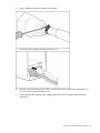
4.
Disconnect the two AC power cables from the power connectors, labeled Primary and Secondary,
on the power inlet box.
5.
Disconnect the network cable from the RJ-45 connector on the power inlet box.
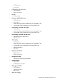
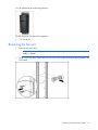
Shutting off the water
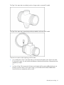
1.
Shut off the water flowing into the MCS unit at the facility-side shut-off valve.
Removal and replacement procedures 25
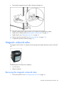
2.
Confirm that no water is flowing into the MCS unit.
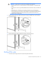
AC transfer switch
The AC transfer switch is located at the bottom front of the MCS unit.
The following tools are required for installation:
•
T-25 Torx driver
•
Small Flathead screwdriver
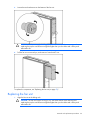
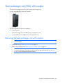
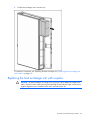
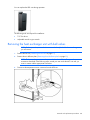
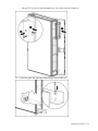
Removing the AC transfer switch
1.
Power down the MCS unit ("Powering down the MCS unit" on page 24).
2.
Open the front MCS door.
3.
Slide the metal AC transfer switch box out toward you on the sliding rails.
Removal and replacement procedures 26
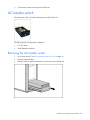
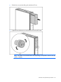
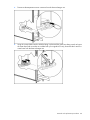
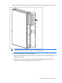
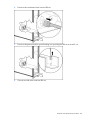
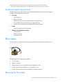
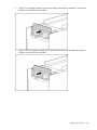
4.
Using a T-25 Torx driver, remove the four Torx screws securing the AC transfer switch chassis to the
water group controller chassis. The transfer switch chassis cannot be completely removed yet
because the cables are still connected.
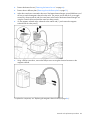
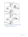
5.
Disconnect the green and yellow ground bonding wires from the water group controller.
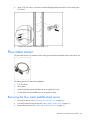
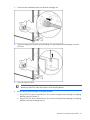
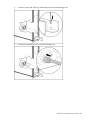
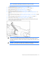
6.
Disconnect the electrical power cables from the rear of the AC transfer switch.
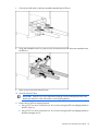
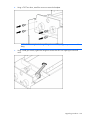
Removal and replacement procedures 27
a. Disconnect the three large cables, starting from the left and moving to the right, by inserting a
small flathead screwdriver in between the cable connection and the latch, and pulling the cable
out from the connector.
b. Disconnect the three small cables, starting from the left and moving to the right, by pressing the
small tab on the bottom of each small cable and pulling it out from the connector.
After you have disconnected all of the cables, the transfer switch chassis is free from restraint and can be
removed from the water group controller chassis.
To replace this component, see "Replacing the AC transfer switch (on page 28)."
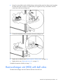
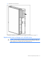
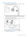
Replacing the AC transfer switch
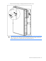
1.
Connect the green and yellow ground bonding wires to the water group controller.
Removal and replacement procedures 28
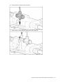
2.
Connect the electrical power cables from the MCS unit to the AC transfer switch.
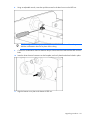
a. Connect the three small cables, starting from the right and moving to the left, by pressing the tab
on the bottom of each cable and pushing it into the connector.
Removal and replacement procedures 29
b. Connect the three large cables, starting from the right and moving to the left, by pushing the
cable into the connector.
3.
Using a T-25 Torx driver, secure the AC transfer switch chassis to the water group controller chassis
by inserting four Torx screws.
CAUTION: To prevent damage to the cables and ensure proper fit of the transfer switch
chassis, be sure to route all cables through the U-shaped opening in the rear of the chassis.
Removal and replacement procedures 30
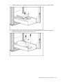
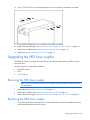
4.
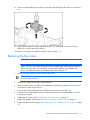
Slide the metal AC transfer switch box back into the MCS unit on the sliding rails.
5.
Complete the operation checklist (on page 111).
Air bleeder valve
The air bleeder valve is located inside the MCS unit, centered at the top of the unit.
The following tools are required for installation:
•
T-25 Torx driver
•
Pliers
•
Water hose fitting wrench (included with your original MCS unit)
•
Counter hold wrench (included with your original MCS unit)
Removing the air bleeder valve
1.
Shut off the water flowing into the MCS unit. ("Shutting off the water" on page 25)
2.
Remove the top fan unit. ("Removing the fan unit" on page 51)
3.
Remove the top heat exchanger unit. ("Removing the heat exchanger unit with couplers" on page
59)
Removal and replacement procedures 31
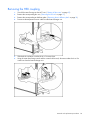
4.
Reach into the access panel cut-out.
5.
Using a pair of pliers, unscrew the air bleeder valve from the check valve.
6.
Remove the air bleeder valve from the MCS unit.
To replace this component, see "Replacing the air bleeder valve (on page 32)."
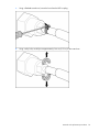
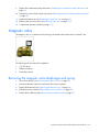
Replacing the air bleeder valve
1.
Reach into the access panel cut-out and align the air bleeder valve to the check valve.
2.
Firmly hand-tighten the air bleeder valve.
Removal and replacement procedures 32
3.
Slightly open the top vent of the air bleeder valve, approximately 3/4 turn, to allow for air flow.
4.
Replace the top heat exchanger unit. ("Replacing the heat exchanger unit with couplers" on page
63)
5.
Replace the top fan unit. ("Replacing the fan unit" on page 52)
6.
Restore water flow to the MCS unit. ("Restoring water flow" on page 112)
7.
Complete the operation checklist (on page 111).
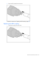
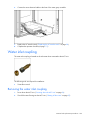
Air deflector plate
The air deflector plate is not a spare part. The removal and replacement instructions for the air deflector
plate are provided so that you can access other components.
No tools are required for this procedure.
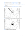
Removing the air deflector plate
1.
Loosen the two thumbscrews securing the air deflector plate to the MCS unit.
2.
Disconnect the green and yellow ground bonding wire.
Removal and replacement procedures 33
3.
Lift the air deflector plate up, tilt it to an angle, and pull it out toward you.
To replace this component, see "Replacing the air deflector plate (on page 34)."
Replacing the air deflector plate
1.
Reattach the ground bonding wires to the air deflector plate.
2.
Align the two screw holes on the air deflector plate to the two screw holes inside the MCS unit.
3.
Secure the air deflector plate to the MCS unit by tightening the two thumbscrews in the two screw
holes.
Air sealing plate
The air sealing plate is not a spare part. The removal and replacement instructions for the air sealing
plate are provided so that you can access other components.
Removal and replacement procedures 34
No tools are required for this procedure.
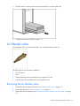
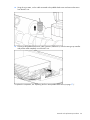
Removing the air sealing plate
1.
Disconnect the condensation hose from the condensation pump by pressing in the plastic collar quick
connect on the condensation pump.
2.
Loosen the two thumbscrews securing the air sealing plate to the MCS unit.
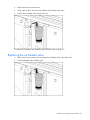
Removal and replacement procedures 35
3.
Slide the air sealing plate out of the MCS unit.
To replace this component, see "Replacing the air sealing plate (on page 36)."
Replacing the air sealing plate
1.
Slide the air sealing plate into the MCS unit.
Removal and replacement procedures 36
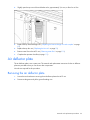
2.
Secure the air sealing plate to the MCS unit by tightening the two thumbscrews.
3.
Connect the condensation hose to the condensation pump by inserting it into the plastic collar quick
connect on the condensation pump.
Removal and replacement procedures 37
Automatic door release
The automatic door release kits are located on the front and rear doors of the rack attached to the MCS
unit.
The following tools are required for installation:
•
3-mm Allen wrench
•
T-25 Torx driver
•
Wire cutters
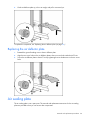
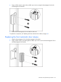
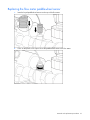
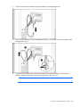
Removing the front automatic door release
1.
Unplug the electromagnetic lock cable from the panel connector on the MCS unit.
Removal and replacement procedures 38
2.
Using an Allen wrench, remove the two black cap screws securing the electromagnetic lock to the
electromagnetic lock bracket.
3.
Remove the electromagnetic lock and cable from the rack.
To replace this component, see "Replacing the front automatic door release (on page 39)."
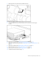
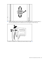
Replacing the front automatic door release
1.
Align the electromagnetic lock to the electromagnetic lock bracket.
2.
Using an Allen wrench, insert and tighten two black cap screws to secure the electromagnetic lock to
the electromagnetic lock bracket.
Removal and replacement procedures 39
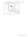
3.
Route the magnetic lock cable down through front extension channel, across the front of the rack,
and plug it into the panel connector on the MCS unit.
Removal and replacement procedures 40
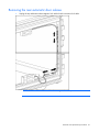
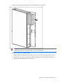
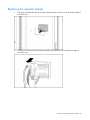
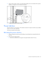
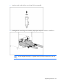
Removing the rear automatic door release
1.
Unplug the top and bottom electromagnetic lock cables from the extension lock cable.
NOTE: Be sure to note the location of the electromagnetic brackets prior to removal.
Removal and replacement procedures 41
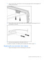
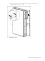
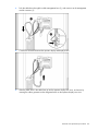
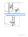
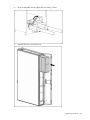
2.
Using a T-25 Torx driver, remove the four screws securing the upper and lower electromagnetic lock
brackets to the rack chassis.
3.
Using an Allen wrench, remove the two black cap screws securing each electromagnetic lock to its
electromagnetic lock bracket.
4.
Remove the electromagnetic locks and cables from the rack.
To replace this component, see "Replacing the rear automatic door release (on page 42)."
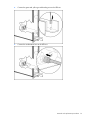
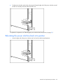
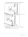
Replacing the rear automatic door release
1.
Align the electromagnetic locks to the electromagnetic lock brackets.
Removal and replacement procedures 42
2.
Using an Allen wrench, insert and tighten two black cap screws to secure each electromagnetic lock
to its electromagnetic lock bracket.
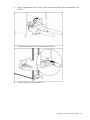
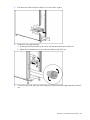
3.
Install the top electromagnetic lock bracket to the rack chassis in the location you noted during
removal.
a. Align the electromagnetic lock assembly to the rack chassis in the location you noted during
removal.
b. Using a T-25 Torx driver, insert and tighten two M5.5 self-tapping screws into the inner row of
rack holes to secure the electromagnetic lock assembly to the rack chassis.
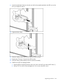
4.
Repeat step 3 for the bottom electromagnetic lock bracket.
Removal and replacement procedures 43
5.
Route the magnetic lock cable through the rear extension channel, across the rack, and plug it into
the panel connector on the MCS unit.
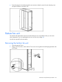
Bottom fan unit
The removal and replacement instructions for the bottom fan unit are provided so that you can access
other components. If you are replacing the fan unit, see Fan unit (on page 50).
No tools are required for this procedure.
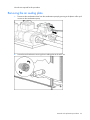
Removing the bottom fan unit
1.
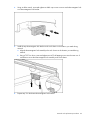
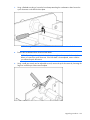
Open the rear MCS door.
2.
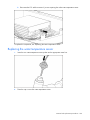
Using a T-25 Torx driver, remove the four Torx screws securing the horizontal shipping bracket to the
MCS frame.
Removal and replacement procedures 44
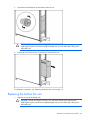
3.
Loosen the two thumbscrews on the bottom of the fan unit.
CAUTION: The fan unit weighs 16.8 kg (37 lb). Use extra caution when removing and
replacing the top fan unit because it might be higher than your shoulders and is heavy and
awkward to lift.
4.
Pull the fan unit out toward you, and remove it from the MCS unit.
To replace this component, see "Replacing the bottom fan unit (on page 45)."
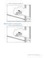
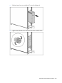
Replacing the bottom fan unit
1.
Align the fan unit to the sliding rails.
CAUTION: The fan unit weighs 16.8 kg (37 lb). Use extra caution when removing and
replacing the top fan unit because it might be higher than your shoulders and is heavy and
awkward to lift.
Removal and replacement procedures 45
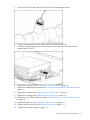
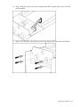
2.
Slide the bottom fan unit inside the MCS unit on the sliding rails.
3.
Tighten the two thumbscrews to secure the fan unit to the MCS frame.
Removal and replacement procedures 46
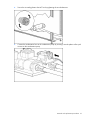
4.
Using a T-25 Torx driver, secure the horizontal shipping bracket to the MCS unit by inserting four
Torx screws.
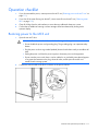
Condensation pump and sensors
The condensation pump and sensors are components of the water group located at the bottom interior of
the MCS unit.
The following tools are required for installation:
•
T-25 Torx driver
•
Phillips screwdriver
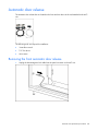
Removing the condensation pump and sensors
1.
Power down the MCS unit ("Powering down the MCS unit" on page 24).
2.
Remove the bottom fan unit ("Removing the bottom fan unit" on page 44).
3.
Relocate the power inlet box ("Relocating the power inlet box" on page 93).
4.
Remove the air sealing plate ("Removing the air sealing plate" on page 35).
Removal and replacement procedures 47
5.
Disconnect the AC power cable from the condensation pump.
6.
Disconnect the two sensor connections from the condensation pump.
Removal and replacement procedures 48
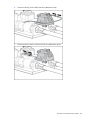
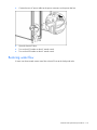
7.
Loosen the thumbscrew on the bottom of the condensation pump securing the condensation pump to
the MCS unit (1), and lift the condensation pump from the MCS unit (2).
To replace the component, see "Replacing the condensation pump and sensors (on page 49)."
Replacing the condensation pump and sensors
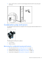
1.
Align the condensation pump thumbscrew to the hole inside the MCS unit (1), and tighten the
thumbscrew on the bottom of the condensation pump to secure it to the MCS unit (2).
Removal and replacement procedures 49
2.
Connect the two sensor connectors to the condensation pump.
3.
Connect the AC power cable to the condensation pump.
4.
Replace the air sealing plate ("Replacing the air sealing plate" on page 36).
5.
Relocate the power inlet box back into position ("Relocating the power inlet box back into position"
on page 95).
6.
Replace the bottom fan unit ("Replacing the bottom fan unit" on page 45).
7.
Complete the operation checklist (on page 111).
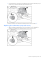
Fan unit
The three fan units are located at the rear of the MCS unit.
Removal and replacement procedures 50
You can replace the fan units during operation.
The following tools are required for installation:
•
T-25 Torx driver
Removing the fan unit
1.
Open the rear MCS door.
NOTE: The number of horizontal brackets varies depending on the position of the fan unit (top,
middle, or bottom).
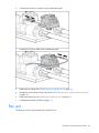
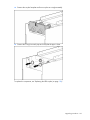
2.
Using a T-25 Torx driver, remove the four Torx screws securing the horizontal shipping bracket to the
MCS frame.
Removal and replacement procedures 51
3.
Loosen the two thumbscrews on the bottom of the fan unit.
CAUTION: The fan unit weighs 16.8 kg (37 lb). Use extra caution when removing and
replacing the top fan unit because it might be higher than your shoulders and is heavy and
awkward to lift.
4.
Pull the fan unit out toward you, and remove it from the MCS unit.
To replace this component, see "Replacing the fan unit (on page 52)."
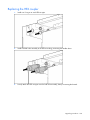
Replacing the fan unit
1.
Align the fan unit to the sliding rails.
CAUTION: The fan unit weighs 16.8 kg (37 lb). Use extra caution when removing and
replacing the top fan unit because it might be higher than your shoulders and is heavy and
awkward to lift.
Removal and replacement procedures 52
2.
Slide the fan unit onto the sliding rails inside the MCS unit.
3.
Tighten the two thumbscrews to secure the fan unit to the MCS frame.
NOTE: The number of horizontal brackets varies depending on the position of the fan unit (top,
middle, or bottom).
Removal and replacement procedures 53
4.
Using a T-25 Torx driver, secure the horizontal shipping bracket to the MCS unit by inserting four
Torx screws.
5.
Complete the operation checklist (on page 111).
Flow meter sensor
The flow meter sensor is a component of the water group located at the bottom interior of the MCS unit.
The following tools are required for installation:
•
T-25 Torx driver
•
Wire cutters
•
Water hose fitting wrench (included with your original MCS unit)
•
Counter hold wrench (included with your original MCS Unit)
Removing the flow meter paddle-wheel sensor
1.
Power down the MCS unit. ("Powering down the MCS unit" on page 24)
2.
Shut off the water flowing into the MCS unit. ("Shutting off the water" on page 25)
3.
Remove the bottom fan unit. ("Removing the bottom fan unit" on page 44)
Removal and replacement procedures 54
4.
Relocate the power inlet box. ("Relocating the power inlet box" on page 93)
5.
Remove the air sealing plate. ("Removing the air sealing plate" on page 35)
6.
Remove the air deflector plate. ("Removing the air deflector plate" on page 33)
7.
Remove the condensation pump and sensors. ("Removing the condensation pump and sensors" on
page 47)
8.
Remove the AC transfer switch. ("Removing the AC transfer switch" on page 26)
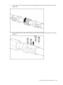
9.
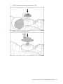
Remove the plastic lock washer from above the paddle-wheel sensor.
10.
Unscrew the plastic screw cap securing the paddle-wheel sensor to the flow meter.
11.
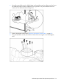
Lift the paddle-wheel sensor up and off the flow meter.
Removal and replacement procedures 55
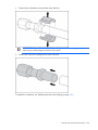
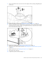
12.
Using the wire cutters, cut the cable connected to the paddle-wheel sensor and remove the sensor
from the MCS unit.
13.
Disconnect the paddle-wheel sensor cable connector, labeled X14, from the water group controller
and pull the cable completely out of the MCS unit.
To replace this component, see "Replacing the flow meter paddle-wheel sensor (on page 57)."
Removal and replacement procedures 56
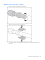
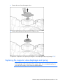
Replacing the flow meter paddle-wheel sensor
1.
Insert the keyed paddle-wheel sensor into the top of the flow meter.
2.
Screw on the plastic screw cap to secure the paddle-wheel sensor to the flow meter.
Removal and replacement procedures 57
3.
Replace the plastic lock washer above the paddle-wheel sensor.
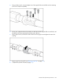
4.
Route the paddle-wheel sensor cable through to the front of the MCS unit.
5.
Connect the paddle-wheel sensor cable connector to the X14 connector on the water group
controller.
6.
Replace the AC transfer switch ("Replacing the AC transfer switch" on page 28).
7.
Replace the condensation pump and sensors ("Replacing the condensation pump and sensors" on
page 49).
8.
Replace the air deflector plate ("Replacing the air deflector plate" on page 34).
9.
Replace the bottom fan unit ("Replacing the bottom fan unit" on page 45).
10.
Restore water flow to the MCS unit ("Restoring water flow" on page 112).
11.
Complete the operation checklist (on page 111).
Removal and replacement procedures 58
Heat exchanger unit (HEX) with coupler
The three heat exchanger units are located on the front of the MCS unit.
You can replace the HEX units during operation.
The following tools are required for installation:
•
T-25 Torx driver
•
Water hose fitting wrench (included with your original MCS unit)
•
Counter hold wrench (included with your original MCS unit)
Removing the heat exchanger unit with couplers
NOTE: For this procedure, remove the fan unit seated directly behind the heat exchanger unit
you will remove.
1.
Remove the fan unit ("Removing the fan unit" on page 51).
2.
Remove the air deflector plate ("Removing the air deflector plate" on page 33).
NOTE: The heat exchanger units are deep-seated within the MCS unit. To access the
connections described in the following steps, extend your arm inside the MCS unit until you
come in contact with the appropriate connectors.
Removal and replacement procedures 59
3.
Disconnect the temperature sensor connector from the heat exchanger unit.
4.
Using the counter hold wrench to hold the fitting in place and the water hose fitting wrench to loosen
the water hose (both wrenches are included with your original MCS unit), disconnect the In and Out
water hoses from the heat exchanger unit.
Removal and replacement procedures 60
5.
Disconnect the condensation hose from the heat exchanger unit.
6.
Disconnect the green and yellow ground bonding wire grounding the heat exchanger unit to the
MCS unit.
7.
Open the front MCS door.
IMPORTANT: Keep the Torx screws separated according to their thread type and note which
thread type came from which hole location on the shipping bracket.
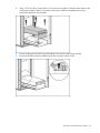
8.
Remove the two heat exchanger unit shipping brackets.
a. Using a T-25 Torx driver, remove the four Torx screws securing the heat exchanger unit shipping
brackets to the MCS frame (1).
b. Using a T-25 Torx driver, remove the four Torx screws securing the heat exchanger unit shipping
brackets to the heat exchanger unit (2).
Removal and replacement procedures 61
c.
Remove the heat exchanger unit shipping brackets from the MCS unit (3).
CAUTION: The heat exchanger unit weighs 23.6 kg (52 lb) with the additional weight of the
water. Use extra caution when removing and replacing the top heat exchanger unit because it
might be higher than your shoulders and is heavy and awkward to lift.
Removal and replacement procedures 62
9.
Pull the heat exchanger unit out toward you.
To replace this component, see "Replacing the heat exchanger unit ("Replacing the heat exchanger unit
with couplers" on page 63)."
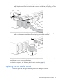
Replacing the heat exchanger unit with couplers
CAUTION: The heat exchanger unit weighs 23.6 kg (52 lb) with the additional weight of the
water. Use extra caution when removing and replacing the top heat exchanger unit because it
might be higher than your shoulders and is heavy and awkward to lift.
Removal and replacement procedures 63
1.
Insert the new heat exchanger unit into the same position as the heat exchanger unit you removed.
IMPORTANT: Keep the Torx screws separated according to their thread type and note which
thread type came from which hole location on the shipping bracket.
2.
Install the two heat exchanger unit shipping brackets.
a. Align the heat exchanger unit shipping brackets to the screw holes on the heat exchanger unit
and the MCS frame (1).
b. Using a T-25 Torx driver, secure the two heat exchanger unit shipping brackets to the heat
exchanger unit by inserting and tightening four Torx screws (2).
Removal and replacement procedures 64
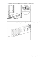
c.
3.
Using a T-25 Torx driver, secure the two shipping brackets to the MCS frame by inserting and
tightening four Torx screws (3).
Open the rear MCS door.
Removal and replacement procedures 65
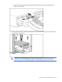
4.
Connect the green and yellow ground bonding wire to the heat exchanger unit.
5.
Connect the condensation hose to the heat exchanger unit.
Removal and replacement procedures 66
6.
Using the counter hold wrench to hold the fitting in place and the water hose fitting wrench to tighten
the water hose (both wrenches are included with your original MCS unit), connect the In and Out
water hoses to the heat exchanger unit.
7.
Connect the temperature sensor connector to the heat exchanger unit.
8.
Replace the air deflector plate ("Replacing the air deflector plate" on page 34).
9.
Replace the fan unit ("Replacing the fan unit" on page 52).
Complete the operation checklist (on page 111).
Heat exchanger unit (HEX) with ball valve
The three heat exchanger units are located on the front of the MCS unit.
Removal and replacement procedures 67
You can replace the HEX units during operation.
The following tools are required for installation:
•
T-25 Torx driver
•
Adjustable wrench or pipe wrench
Removing the heat exchanger unit with ball valves
NOTE: For this procedure, remove the fan unit seated directly behind the heat exchanger unit
you will remove.
1.
Remove the fan unit ("Removing the fan unit" on page 51).
2.
Remove the air deflector plate ("Removing the air deflector plate" on page 33).
NOTE: The heat exchanger units are deep-seated within the MCS unit. To access the
connections described in the following steps, extend your arm inside the MCS unit until you
come in contact with the appropriate connectors.
3.
Disconnect the temperature sensor connector from the HEX unit.
Removal and replacement procedures 68
4.
Disconnect the condensation hose from the HEX unit.
5.
Disconnect the green and yellow ground bonding wire grounding the HEX unit to the MCS unit.
6.
Close the two ball valves inside the HEX unit.
Removal and replacement procedures 69
7.
Close the two ball valves on the hose assemblies attached to the HEX unit.
8.
Using and adjustable wrench or a pipe wrench, disconnect the two ball valve hose assemblies from
the HEX unit.
9.
Wipe up any excess water from the hoses.
10.
Open the front MCS door.
IMPORTANT: Keep the Torx screws separated according to their thread type and note which
thread type came from which hole location on the shipping bracket.
11.
Remove the two HEX unit shipping brackets.
a. Using a T-25 Torx driver, remove the four Torx screws securing the HEX unit shipping brackets to
the MCS frame (1).
b. Using a T-25 Torx driver, remove the four Torx screws securing the HEX unit shipping brackets to
the heat exchanger unit (2).
Removal and replacement procedures 70
c.
Remove the HEX unit shipping brackets from the MCS unit (3).
CAUTION: The heat exchanger unit weighs 23.6 kg (52 lb) with the additional weight of the
water. Use extra caution when removing and replacing the top heat exchanger unit because it
might be higher than your shoulders and is heavy and awkward to lift.
Removal and replacement procedures 71
12.
Pull the HEX unit out toward you.
To replace this component, see "Replacing the heat exchanger unit with ball valves (on page 72)."
Replacing the heat exchanger unit with ball valves
CAUTION: The heat exchanger unit weighs 23.6 kg (52 lb) with the additional weight of the
water. Use extra caution when removing and replacing the top heat exchanger unit because it
might be higher than your shoulders and is heavy and awkward to lift.
Removal and replacement procedures 72
1.
Insert the new HEX unit into the same position as the HEX unit you removed.
IMPORTANT: Keep the Torx screws separated according to their thread type and note which
thread type came from which hole location on the shipping bracket.
2.
Install the two HEX unit shipping brackets.
a. Align the HEX unit shipping brackets to the screw holes on the HEX unit and the MCS frame (1).
b. Using a T-25 Torx driver, secure the two HEX unit shipping brackets to the heat exchanger unit
by inserting and tightening four Torx screws (2).
Removal and replacement procedures 73
c.
3.
Using a T-25 Torx driver, secure the two HEX unit shipping brackets to the MCS frame by
inserting and tightening four Torx screws (3).
Open the rear MCS door.
Removal and replacement procedures 74
4.
Connect the green and yellow ground bonding wire to the HEX unit.
5.
Connect the condensation hose to the HEX unit.
Removal and replacement procedures 75
6.
Using an adjustable wrench or a pipe wrench, connect the two ball valve hose assemblies to the
HEX unit.
7.
Connect the temperature sensor connector to the HEX unit.
8.
Open the ball valves inside the HEX unit.
Removal and replacement procedures 76
9.
Open the ball valves on the hose assemblies.
10.
Confirm that water is flowing through the ball valve couplers, by touching the couplers. The couplers
should be cold.
11.
Replace the hose insulation over the couplers.
12.
Replace the air deflector plate ("Replacing the air deflector plate" on page 34).
13.
Replace the fan unit ("Replacing the fan unit" on page 52).
14.
Complete the operation checklist (on page 111).
HEX coupling
The three HEX couplings are located at the rear of each HEX unit iinside the MCS unit.
The following tools are required for installation:
•
T-25 Torx driver
•
Water hose fitting wrench (included with your original MCS unit)
•
Counter hold wrench (included with your original MCS unit)
•
Flathead screwdriver
•
Utility knife
Removal and replacement procedures 77
Removing the HEX coupling
1.
Shut off the water flowing into the MCS unit. ("Shutting off the water" on page 25)
2.
Remove the corresponding fan unit. ("Removing the fan unit" on page 51)
3.
Remove the corresponding air deflector plate. ("Removing the air deflector plate" on page 33)
4.
Disconnect the temperature sensor cable from the heat exchanger unit.
5.
Slide back the insulation on either the In or Out water hose.
6.
Using the water hose fitting wrench and the counter hold wrench, disconnect either the In or Out
water hose from the heat exchanger unit.
Removal and replacement procedures 78
7.
Using a flathead screwdriver, loosen the hose from the HEX coupling.
8.
Using a utility knife, carefully trim approximately 0.64 cm (0.25 in) off the water hose.
Removal and replacement procedures 79
9.
Remove the HEX coupling from the water hose.
To replace this component, see "Replacing the HEX coupling (on page 80)."
Replacing the HEX coupling
1.
Insert the HEX coupling into the water hose.
Removal and replacement procedures 80
2.
Using a flathead screwdriver, tighten the hose clamp.
3.
Connect the HEX coupling to the heat exchanger unit.
4.
Using the water hose fitting wrench and the counter hold wrench, reconnect the appropriate In or
Out water hose to the heat exchanger unit.
5.
Confirm that the HEX coupling is fully engaged between the heat exchanger bulkhead and the
coupling nut.
Removal and replacement procedures 81
6.
Reconnect the temperature sensor cable to the heat exchanger unit.
7.
Slide the insulation back in place on the In or Out water hose up against the coupling.
8.
Replace the air deflector plate ("Replacing the air deflector plate" on page 34).
9.
Replace the fan unit ("Replacing the fan unit" on page 52).
10.
Restore water flow to the MCS unit ("Restoring water flow" on page 112).
11.
Complete the operation checklist (on page 111).
Magnetic solenoid valve
The magnetic solenoid valve is a component of the water group located at the bottom interior of the MCS
unit.
The following tools are required for installation:
•
T-25 Torx driver
•
Phillips screwdriver
Removing the magnetic solenoid valve
1.
Power down the MCS unit ("Powering down the MCS unit" on page 24).
Removal and replacement procedures 82
2.
Remove the bottom fan unit ("Removing the bottom fan unit" on page 44).
3.
Remove the air deflector plate ("Removing the air deflector plate" on page 33).
4.
Adjust the water hoses connected to the rear of the bottom heat exchanger unit and hold them out of
the way to reach the magnetic solenoid on the valve. This process can be difficult. If you struggle
excessively, disconnect the In and Out water hoses on the back of the bottom heat exchanger unit
using the counter hold wrench and the water hose fitting wrench.
5.
On the magnetic solenoid valve, release the silver retainer tab (1), and remove the magnetic
solenoid from the valve post (2).
6.
Using a Phillips screwdriver, remove the Phillips screw securing the electrical connector to the
magnetic solenoid.
To replace the component, see "Replacing the magnetic solenoid valve (on page 84)."
Removal and replacement procedures 83
Replacing the magnetic solenoid valve
1.
Using a Phillips screwdriver, connect the electrical connector from the MCS unit to the magnetic
solenoid by inserting and tightening one Phillips screw.
2.
Adjust the water hoses connected to the rear of the bottom heat exchanger unit and hold them out of
the way to reach the solenoid valve post. This process can be difficult. If you struggle excessively,
disconnect the In and Out water hoses connected to the bottom heat exchanger unit using the
counter hold wrench and the water hose fitting wrench.
3.
Place the magnetic solenoid back on the valve post (1), and press down until the silver retainer tab
locks the magnetic solenoid in place on the valve (2).
4.
Replace the air deflector plate ("Replacing the air deflector plate" on page 34).
5.
Replace the bottom fan unit ("Replacing the bottom fan unit" on page 45).
6.
Complete the operation checklist (on page 111).
Removal and replacement procedures 84
Management module
The management module is located on the inside of the front door of the MCS unit.
No tools are required for this procedure.
Removing the management module
1.
Power down the MCS unit ("Powering down the MCS unit" on page 24).
2.
Open the front MCS door.
3.
Disconnect the electrical cables from the management module.
Removal and replacement procedures 85
4.
Slide the management module off of the mounting bracket, and remove it from the inside of the front
MCS door.
To replace this component, see "Replacing the management module (on page 86)."
Replacing the management module
1.
Slide the management module onto the mounting bracket until it locks in place.
CAUTION: To avoid damage to the management module connectors, do not allow the cables
to pull on the management module connectors.
Removal and replacement procedures 86
2.
Connect the electrical cables from the MCS unit to the management module.
3.
Power on the management module.
4.
Press and hold the C key for five seconds to confirm the configuration settings.
5.
Complete the operation checklist (on page 111).
Removal and replacement procedures 87
Operator display
The operator display is located on the front door of the MCS unit.
The following tools are required for installation:
•
8-mm socket
•
Small Flathead screwdriver
Removing the operator display
1.
Power down the MCS unit ("Powering down the MCS unit" on page 24).
2.
Open the front MCS door.
3.
Using an 8 mm socket or wrench, remove the three nuts and external star washers securing the
operator display rear cover to the back of the front MCS door.
4.
Remove the operator display rear cover.
Removal and replacement procedures 88
5.
Disconnect the connector between the operator display and the display button.
6.
Disconnect the connector from the management module (1), and pull the cable up through the cable
management hose (2).
7.
Squeeze the four release tabs on the top and bottom of the operator display (1), and push the
operator display from the back to the front through the front MCS door (2).
NOTE: Cables are removed for clarity.
Removal and replacement procedures 89
8.
Remove the display button by squeezing the two release tabs on the sides of the display button (1)
and pushing the display button from the back to the front through the front MCS door (2).
To replace this component, see "Replacing the operator display (on page 91)."
Removal and replacement procedures 90
Replacing the operator display
1.
Hold the four release tabs while pushing the operator display from the front to the back through the
front MCS door.
2.
Hold the two release tabs while pushing the display button from the front to the back through the
front MCS door.
Removal and replacement procedures 91
3.
Push the cable down through the cable management hose (1), and connect it to the management
module connector (2).
4.
Connect the connector between the operator display and display button.
5.
Slide any extra slack in the cable lines up into the operator display rear cover, and secure by
inserting the rubber grommet into the designated notch on the operator display rear cover.
Removal and replacement procedures 92
6.
Using an 8 mm socket or wrench, secure the operator display rear cover to the back of the operator
display by inserting three nuts and external star washers.
7.
Complete the operation checklist (on page 111).
Power inlet box
The power inlet box is not a spare part. The relocation instructions for the power inlet box are provided so
that you can access other components.
No tools are required for this procedure.
Relocating the power inlet box
1.
Disconnect the green and yellow ground bonding wire grounding the outer support bracket to the
MCS unit.
2.
Remove the outer support bracket.
a. Loosen the four thumbscrews securing the outer support bracket to the MCS unit (1).
Removal and replacement procedures 93
b. Lift the right side of the bracket up at a slant, and pull the bracket out of the MCS unit (2).
IMPORTANT: Do not disconnect any of the internal electrical connections to the power inlet
box.
3.
Pull the power inlet box toward you until it stops.
Removal and replacement procedures 94
4.
Set the power inlet box aside in the side cavity by lifting the right side of the power inlet box up until
the box sits vertically on the left side of the MCS unit.
To replace this component, see "Relocating the power inlet box back into position (on page 95)."
Relocating the power inlet box back into position
1.
Lower the right side of the power inlet box until it is back into the horizontal position.
Removal and replacement procedures 95
2.
Push the power inlet box back into the MCS unit until it locks in place.
3.
Replace the outer support bracket.
a. Lift the right side of the bracket up at a slant, and slide the bracket into the MCS unit.
b. Tighten the four thumbscrews to secure the outer bracket to the MCS unit.
4.
Connect the green and yellow ground bonding wire to ground the outer support bracket to the MCS
unit.
Removal and replacement procedures 96
Water group controller
The water group controller is located at the bottom front of the MCS unit.
The following tools are required for installation:
•
T-25 Torx driver
•
Flathead screwdriver
•
8-mm socket
Removing the water group controller
1.
Power down the MCS unit ("Powering down the MCS unit" on page 24).
2.
Remove the AC transfer switch ("Removing the AC transfer switch" on page 26).
3.
Disconnect the seven electrical cables in the front of the water group controller.
Removal and replacement procedures 97
4.
Using an 8 mm socket, remove the two 8 mm nuts and washers securing the water group controller
bracket to the water group controller chassis.
5.
Disconnect the two large electrical cables from the back of the water group controller.
6.
Disconnect the green and yellow grounding wire securing the water group controller to the water
group controller chassis.
Removal and replacement procedures 98
7.
Remove the water group controller (mounted on a bracket) from the water group controller chassis.
8.
Slide the water group controller off of the mounting bracket.
To replace this component, see "Replacing the water group controller (on page 100)."
Removal and replacement procedures 99
Replacing the water group controller
1.
Slide the water group controller onto the mounting bracket until it locks in place.
2.
Connect the green and yellow grounding wire to secure the water group controller to the water
group controller chassis.
3.
Connect the two large electrical cables to the back of the water group controller.
Removal and replacement procedures 100
4.
Place the water group controller (mounted on the bracket) in the water group controller chassis.
5.
Using an 8 mm socket, secure the water group controller bracket to the water group controller
chassis by inserting two washers and two 8 mm nuts.
Removal and replacement procedures 101
6.
Connect the seven electrical cables to the front of the water group controller.
7.
Replace the AC transfer switch ("Replacing the AC transfer switch" on page 28).
8.
Complete the operation checklist (on page 111).
Water inlet coupling
The water inlet coupling is located on the inlet water hose connected to the MCS unit.
The following tools are required for installation:
•
5-mm Allen wrench
Removing the water inlet coupling
1.
Power down the MCS unit. ("Powering down the MCS unit" on page 24)
2.
Shut off the water flowing into the MCS unit. ("Shutting off the water" on page 25)
Removal and replacement procedures 102
3.
Using a pipe wrench, loosen the water inlet coupling and disconnect the water inlet hose from the
supply hose.
4.
Using an Allen wrench, remove the four Allen nuts and bolts securing the two brackets to the water
inlet hose.
Removal and replacement procedures 103
5.
Remove the two brackets from around the water inlet hose.
IMPORTANT: Water will drain out of the hose when you remove the coupling. Be prepared to
catch excess water drainage in a bucket or floor drain.
6.
Remove the water inlet coupling from the water inlet hose.
To replace this component, see "Replacing the water inlet coupling (on page 105)."
Removal and replacement procedures 104
Replacing the water inlet coupling
1.
Insert the water inlet coupling into the water inlet hose.
2.
Align the two brackets around the water inlet hose.
3.
Using an Allen wrench, insert and tighten three 40-mm Allen nuts and bolts into three of the four
screw holes.
Removal and replacement procedures 105
4.
Using an Allen wrench, insert and tighten one of the original Allen nuts and bolts into the remaining
screw hole. Compress completely.
5.
One by one, replace the three 40-mm Allen nuts and bolts with the original Allen nuts and bolts, until
the brackets are firmly compressed around the water inlet hose.
6.
Using a pipe wrench, reconnect the water inlet hose to the supply hose and tighten the water inlet
coupling.
7.
Restore water flow to the MCS unit ("Restoring water flow" on page 112).
8.
Complete the operation checklist (on page 111).
Removal and replacement procedures 106
Water temperature sensor
The water temperature sensor is a component of the water group located at the bottom interior of the
MCS unit.
The following tools are required for installation:
•
T-25 Torx driver
•
Phillips screwdriver
•
(2) 18-mm wrench
•
Wire cutters
Removing the water temperature sensor
1.
Power down the MCS unit. ("Powering down the MCS unit" on page 24)
2.
Shut off the water flowing into the MCS unit. ("Shutting off the water" on page 25)
3.
Remove the bottom fan unit. ("Removing the bottom fan unit" on page 44)
4.
Relocate the power inlet box. ("Relocating the power inlet box" on page 93)
5.
Remove the air sealing plate. ("Removing the air sealing plate" on page 35)
6.
Remove the air deflector plate. ("Removing the air deflector plate" on page 33)
7.
Remove the condensation pump and sensors. ("Removing the condensation pump and sensors" on
page 47)
8.
Remove the AC transfer switch. ("Removing the AC transfer switch" on page 26)
NOTE: HP recommends removing the In and Out water hoses and all cables to the bottom
heat exchanger unit in order to gain greater access.
Removal and replacement procedures 107
9.
Using two 18-mm wrenches, loosen the cap nut from the water temperature sensor.
10.
Using the wire cutters, cut the cable connected to the water temperature sensor, and remove the
water temperature probe and cable from the MCS unit.
11.
Disconnect the appropriate water temperature sensor cable connector from the water group
controller and pull the cable completely out of the MCS unit.
a. Disconnect the X12 cable connector if you are repairing the inlet water temperature sensor.
Removal and replacement procedures 108
b. Disconnect the X13 cable connector if you are repairing the outlet water temperature sensor.
To replace this component, see "Replacing the water temperature sensor."
Replacing the water temperature sensor
1.
Insert the new water temperature sensor probe into the appropriate water line.
2.
Place the cap nut over the water temperature sensor.
Removal and replacement procedures 109
3.
Using two 18-mm wrenches, tighten the cap nut over the water temperature sensor.
4.
Route the water temperature sensor cable through to the front of the MCS unit.
5.
Connect the water temperature sensor cable connector to the water group controller connector
labeled either X12 or X13.
6.
Replace the AC transfer switch ("Replacing the AC transfer switch" on page 28).
7.
Replace the condensation pump and sensors ("Replacing the condensation pump and sensors" on
page 49).
8.
Replace the air deflector plate ("Replacing the air deflector plate" on page 34).
9.
Replace the air sealing plate ("Replacing the air sealing plate" on page 36).
10.
Relocate the power inlet box back into position ("Relocating the power inlet box back into position"
on page 95).
11.
Replace the bottom fan unit ("Replacing the bottom fan unit" on page 45).
12.
Restore water flow to the MCS unit ("Restoring water flow" on page 112).
13.
Complete the operation checklist (on page 111).
Removal and replacement procedures 110
Operation checklist
1.
If you disconnected the power, restore power to the MCS unit ("Restoring power to the MCS unit" on
page 111).
2.
If you shut off the water flowing into the MCS, restore water flow to the MCS unit ("Restoring water
flow" on page 112).
3.
Clear all old logs from the web interface to ensure that any additional alarms are current.
4.
Confirm that no additional warning or alarm messages have been detected by looking at the
operator display.
Restoring power to the MCS unit
1.
Open the rear MCS door.
WARNING: To reduce the risk of electric shock or damage to the equipment:
• Do not disable the power cord grounding plug. The grounding plug is an important safety
feature.
• Plug the power cord into a grounded (earthed) electrical outlet that is easily accessible at all
times.
• Unplug the power cord from the power supply to disconnect power to the equipment.
• Do not route the power cord where it can be walked on or pinched by items placed against
it. Pay particular attention to the plug, electrical outlet, and the point where the cord
extends from the storage system.
2.
Connect the network cable to the RJ-45 connector on the power inlet box.
Removal and replacement procedures 111
3.
Connect the two AC power cables to the power connectors on the power inlet box.
4.
Open the front MCS door.
5.
Turn on the AC1 breaker on the AC transfer switch.
6.
Turn on the AC2 breaker on the AC transfer switch.
Restoring water flow
If water was disconnected, restore water flow to the MCS unit at the facility-side valve.
Removal and replacement procedures 112
Technician repair removal and replacement
procedures
WARNING: You must follow the removal and replacement instructions listed in the site
preparation guide, the user guide, and the maintenance and service guide. Failure to follow
the instructions listed in these guides can void your warranty and service contract.
The customer can order the miscellaneous hardware kit, but it will be delivered by a trained HP service
technician, who will then install the new spare kit by following the removal and replacement instructions in
this chapter.
Miscellaneous hardware kit overview
IMPORTANT: The following procedures should only be performed by an HP trained technician.
Description
Spare part number
Customer self repair
SPS- HARDWARE KIT,
407165-001
MISC ("Miscellaneous
hardware kit overview" on
page 113)
No
A) Magnetic valve
diaphragm and spring*
—
—
B) Flow meter
—
—
C) Gasket**
—
—
Technician repair removal and replacement procedures 113
*Only the diaphragm and spring are shown, though the entire magnetic valve ships in the kit.
**The removal and replacement instructions for this component are not included in this document.
Technician repair required tools
The following tools are required for the removal and replacement instructions for each component
included in the miscellaneous hardware kit:
•
•
Flow meter
o
T-25 Torx driver
o
Phillips screwdriver
o
Water hose fitting wrench (included with your original MCS unit)
o
Counter hold wrench (included with your original MCS unit)
o
46 mm wrench (included in the miscellaneous hardware spare kit)
Gasket
No tools are required for this procedure.
•
Magnetic valve diaphragm and spring
o
T-25 Torx driver
o
Phillips screwdriver
o
8 mm Allen wrench
Flow meter
The flow meter is a component of the water group located at the bottom interior of the MCS unit.
The following tools are required for installation:
•
T-25 Torx driver
•
Phillips screwdriver
•
Water hose fitting wrench (included with your original MCS unit)
•
Counter hold wrench (included with your original MCS unit)
•
46-mm wrench (included with the miscellaneous hardware spare kit)
Removing the flow meter
Technician repair removal and replacement procedures 114
NOTE: This procedure is specifically for the removal of the Type 1 flow meter.
1.
Power down the MCS unit ("Powering down the MCS unit" on page 24).
2.
Shut off the water flowing into the MCS unit ("Shutting off the water" on page 25).
3.
Remove the bottom fan unit ("Removing the bottom fan unit" on page 44).
4.
Relocate the power inlet box ("Relocating the power inlet box" on page 93).
5.
Remove the condensation pump and sensors ("Removing the condensation pump and sensors" on
page 47).
6.
Remove the bottom heat exchanger unit ("Removing the heat exchanger unit with couplers" on page
59).
7.
Remove the magnetic solenoid valve ("Removing the magnetic solenoid valve" on page 82).
8.
Remove the AC transfer switch ("Removing the AC transfer switch" on page 26).
9.
Using the 46-mm wrench (included in the miscellaneous hardware kit), loosen the two flow meter
union nuts securing the flow meter in place.
WARNING: To reduce the risk of electric shock or damage to the equipment, use extreme
caution when removing and replacing components that involve water around the electrical
wires and unsecured power inlet box. There is great risk of electrical shock when water is used
near electricity.
WARNING: To reduce the risk of electric shock or damage to the equipment, be prepared to
clean up the water from the disconnected water line with towels and sponges.
Technician repair removal and replacement procedures 115
10.
Remove the flow meter from the water line.
11.
Remove the two fiber gaskets on either side of the water line.
Technician repair removal and replacement procedures 116
12.
Disconnect the threaded pick-up at the top of the flow meter and pull the flow meter out of the MCS
unit.
13.
Remove the threaded pick-up and cable from the MCS unit, and disconnect from the connector
labeled X14 on the water group controller.
To replace this component, see "Replacing the flow meter (on page 117)."
Replacing the flow meter
NOTE: This procedure is specifically for the replacement of the Type 2 flow meter.
NOTE: The Type 2 flow meter should arrive with the paddle-wheel sensor already installed in
the top of the flow meter. For information concerning the installation of the paddle-wheel
sensor, see Replacing the flow meter paddle-wheel sensor (on page 57).
1.
Insert the two fiber gaskets on either side of the flow meter.
IMPORTANT: Be sure the arrow on the flow meter is pointing toward the rear of the MCS unit
to ensure proper water flow.
2.
Insert the flow meter back into place on the water line.
3.
Using the 46-mm wrench (included in the miscellaneous hardware kit), tighten the two union nuts to
secure the flow meter to the water line.
4.
Route the flow meter paddle-wheel sensor cable through to the front of the MCS unit.
5.
Connect the flow meter paddle-wheel sensor cable connector to the connector labeled X14 on the
water group controller.
6.
Replace the AC transfer switch ("Replacing the AC transfer switch" on page 28).
7.
Replace the magnetic solenoid valve ("Replacing the magnetic solenoid valve" on page 84).
8.
Replace the bottom heat exchanger unit ("Replacing the heat exchanger unit with couplers" on page
63).
Technician repair removal and replacement procedures 117
9.
Replace the condensation pump and sensors ("Replacing the condensation pump and sensors" on
page 49).
10.
Relocate the power inlet box back into position ("Relocating the power inlet box back into position"
on page 95).
11.
Replace the bottom fan unit ("Replacing the bottom fan unit" on page 45).
12.
Restore water flow to the MCS unit ("Restoring water flow" on page 112).
13.
Complete the operation checklist (on page 111).
Magnetic valve
The magnetic valve is a component of the water group located at the bottom interior of the MCS unit.
The following tools are required for installation:
•
T-25 Torx driver
•
Phillips screwdriver
•
8-mm Allen wrench
Removing the magnetic valve diaphragm and spring
1.
Power down the MCS unit ("Powering down the MCS unit" on page 24).
2.
Disconnect the main water lines at the quick disconnect couplings.
3.
Remove the bottom fan unit ("Removing the bottom fan unit" on page 44).
4.
Relocate the power inlet box ("Relocating the power inlet box" on page 93).
5.
Remove the air deflector plate ("Removing the air deflector plate" on page 33).
Technician repair removal and replacement procedures 118
6.
Using the counter hold wrench to hold the fitting in place and the water hose fitting wrench to loosen
the water hose (both wrenches included with your original MCS unit), disconnect the In and Out
water hoses from the bottom heat exchanger unit.
7.
Remove the magnetic solenoid valve ("Removing the magnetic solenoid valve" on page 82).
8.
Using an 8 mm Allen wrench, remove the four socket screws securing the cover of the magnetic
valve.
Technician repair removal and replacement procedures 119
9.
Remove the cover from the magnetic valve.
10.
Remove the diaphragm and spring from the magnetic valve.
To replace this component, see "Replacing the magnetic valve diaphragm and spring (on page 120)."
Replacing the magnetic valve diaphragm and spring
NOTE: When you replace the diaphragm inside the magnetic valve, be sure to line up the tab
of the diaphragm with the indentation of the magnetic valve. If it is not aligned properly, the
cover will not fit correctly, which could cause further problems.
Technician repair removal and replacement procedures 120
1.
Place the diaphragm and spring on the magnetic valve.
2.
Place the cover on the magnetic valve.
Technician repair removal and replacement procedures 121
3.
Using an 8 mm Allen wrench, secure the cover to the magnetic valve by inserting and tightening four
socket screws.
4.
Replace the magnetic solenoid valve ("Replacing the magnetic solenoid valve" on page 84).
5.
Using the counter hold wrench to hold the fitting in place and the water hose fitting wrench to tighten
the water hose (both wrenches included in your original hardware kit), connect the In and Out water
hoses to the bottom heat exchanger unit.
6.
Replace the air deflector plate ("Replacing the air deflector plate" on page 34).
7.
Relocate the power inlet box back into position ("Relocating the power inlet box back into position"
on page 95).
8.
Replace the bottom fan unit ("Replacing the bottom fan unit" on page 45).
9.
Reconnect the main water lines.
10.
Complete the operation checklist (on page 111).
Technician repair removal and replacement procedures 122
Upgrading procedures
Viewing the upgrade procedures video
Because of the difficulty of removing and replacing spare parts, HP recommends watching the HP
Modular Cooling System Spare Replacement video. This video provides further explanation and detail of
replacement strategies and techniques that might be helpful when attempting to remove and replace spare
parts. You can access the video on the HP website (http://www.hp.com/go/mcs).
1.
Select HP Modular Cooling System.
2.
Under Related Links, select HP Support and Drivers.
3.
Select HP Modular Cooling System.
4.
Under Resources for HP Modular Cooling System, select Customer self repair steps
(videos/animations).
5.
Select either Heat Exchanger Upgrade or Main Hose Upgrade.
Upgrading the HEX coupler
The HEX couplers are located on the HEX units.
The following tools are required for installation:
•
T-25 Torx driver
•
Small pipe wrench
•
Adjustable wrench
•
Flathead screwdriver
•
Knife
Removing the HEX coupler
NOTE: For this procedure, remove the fan unit seated directly behind the heat exchanger unit
you will remove.
1.
Remove the fan unit ("Removing the fan unit" on page 51).
2.
Remove the air deflector plate ("Removing the air deflector plate" on page 33).
3.
Remove the heat exchanger unit ("Removing the heat exchanger unit with couplers" on page 59).
4.
Turn the HEX unit over to access the bottom of the assembly.
Upgrading procedures 123
5.
Using a T-25 Torx driver, remove the three screws on each side of the bottom cover plate and
remove the bottom cover plate from the HEX unit.
6.
Using a flathead screwdriver, push in the tabs of the white electrical connector of the temperature
sensor and push the connector into the HEX unit.
Upgrading procedures 124
7.
Using a flathead screwdriver, loosen the hose clamps attaching the condensation drain hose to the
quick disconnect on the HEX unit face plate.
NOTE: You might need to cut the condensation drain hose to remove it from the barbs.
8.
Remove the condensation drain hose from both barbs.
NOTE: Depending on the style of the hose barb, you might need to remove the hose barb
before you remove the quick disconnect. If the hose barb is chrome-plated, remove it before
you remove the quick disconnect.
9.
Using a small pipe wrench and an adjustable wrench, remove the quick disconnect by loosening the
large nut inside the quick disconnect faceplate.
Upgrading procedures 125
10.
Using a small pipe wrench, loosen the nut attaching the HEX unit copper pipe to each of the ball
valve assemblies.
11.
Using a T-25 Torx driver, remove the four screws securing the coupler face plate to the HEX unit.
Upgrading procedures 126
12.
Remove the coupler faceplate and hose couplers as a single assembly.
13.
Remove the O-ring from each pipe and verify that the pipe is clean.
To replace this component, see "Replacing the HEX coupler (on page 128)."
Upgrading procedures 127
Replacing the HEX coupler
1.
Install one O-ring on to each HEX unit pipe.
2.
Install each ball valve assembly to the HEX unit tubing, positioning the handles down.
3.
Loosely attach the HEX unit pipe nut to the ball valve assembly, barely connecting the threads.
Upgrading procedures 128
4.
Align the first faceplate (faceplate with eight side holes) to the ball valve assemblies, and slide the
faceplate over the ball valve assemblies.
5.
Align the second faceplate (faceplate with round holes) to the ball valve assemblies and slide the
faceplate over the ball valve assemblies.
Upgrading procedures 129
6.
Using a T-25 Torx driver, install four screws to secure the faceplate.
NOTE: Do not overtighten the fittings. The gasket needs only a slight compression to seal the
fitting.
7.
Using a small pipe wrench, tighten the fitting that connects the HEX unit copper pipe to the ball
valve.
Upgrading procedures 130
8.
Using an adjustable wrench, insert the quick disconnect for the drain hose in to the HEX unit.
TIP: Use a light lubrication spray to ease installation of the hose barbs and hose clamps to
hold the condensation drain line in place while working.
9.
Connect the condensation drain line between the quick disconnect hose barb and the HEX unit hose
barb.
10.
Insert the white electrical connector into the faceplate, and verify that the tabs have locked in place.
11.
Align the bottom cover plate to the bottom of HEX unit.
Upgrading procedures 131
12.
Using a T-25 Torx driver, insert and tighten three screws on each side of the bottom cover plate.
13.
Turn the HEX unit right-side up, so it is sitting on the bottom cover plate.
14.
Replace the heat exchanger unit ("Replacing the heat exchanger unit with couplers" on page 63).
15.
Replace the air deflector plate ("Replacing the air deflector plate" on page 34).
16.
Replace the fan unit ("Replacing the fan unit" on page 52).
Upgrading the HEX hose coupler
The HEX hose coupler is a component of the HEX unit with ball valves that connects the HEX unit to the
main water lines.
The following tools are required for installation:
•
Adjustable wrench
•
Knife
•
T-25 Torx driver
Removing the HEX hose coupler
NOTE: For this procedure, remove the fan unit seated directly behind the heat exchanger unit
you will remove.
1.
Remove the fan unit ("Removing the fan unit" on page 51).
2.
Remove the air deflector plate ("Removing the air deflector plate" on page 33).
3.
Remove the heat exchanger unit ("Removing the heat exchanger unit with couplers" on page 59).
Replacing the HEX hose coupler
1.
Verify that the ball valves inside the HEX unit and the ball valves on the hose assemblies are closed,
with the handles perpendicular to the valves.
Upgrading procedures 132
2.
Insert the washer inside the hose union fitting of the hose assembly.
3.
Hand-tighten the union fitting on the assembly, aligning the compression washer to the HEX unit.
NOTE: Do not overtighten the fittings. The gasket needs only a slight compression to seal the
fitting.
Upgrading procedures 133
4.
Using an adjustable wrench, tighten the union fitting 1/8 flat.
5.
Insert the HEX unit in to the MCS unit.
Upgrading procedures 134
6.
Connect the right-side ball valve hose to the left-side MCS return hose. Connect the left-side ball
valve hose to the right-side MCS return hose. The hoses create a criss-cross pattern.
7.
Cut the hose attached to the old coupler the same length of the replacement hose, and insert the
hose barb from the HEX unit into the hose.
8.
Remove the old coupler from the MCS unit.
9.
Transfer the hose insulation from the old hose assembly to the new ball valve hose assembly,
attached to the HEX unit.
10.
Push the insulation back on the cut hose, and install a hose clamp.
Upgrading procedures 135
11.
Insert the barbed-end of the hose from the new ball valve assembly attached to the HEX unit into the
hose you clamped in step 10.
12.
Tighten the hose clamp.
13.
Slide the insulation back over the hose and secure with tie wraps.
14.
Repeat steps 7 through 13 for the other HEX unit hose.
15.
Open the valves inside the HEX unit and on each hose assembly.
16.
Install the two HEX unit shipping brackets.
a. Align the HEX unit shipping brackets to the screw holes on the HEX unit and the MCS frame (1).
b. Using a T-25 Torx driver, insert and tighten four Torx screws to the HEX unit (2).
Upgrading procedures 136
c.
17.
Using a T-25 Torx driver, insert and tighten four Torx screws to the MCS frame (3).
Connect the green and yellow ground bonding wire to the HEX unit.
Upgrading procedures 137
18.
Connect the condensation hose to the HEX unit.
19.
Connect the temperature sensor cable to the HEX unit.
20.
Replace the air deflector plate ("Replacing the air deflector plate" on page 34).
21.
Replace the fan unit ("Replacing the fan unit" on page 52).
22.
Complete the operation checklist (on page 111).
Upgrading procedures 138
Maintenance
Maintenance and service
For information on maintenance and service, refer to the HP website (http://www.hp.com).
Air and water heat exchanger maintenance
The air and water heat exchanger requires no maintenance. If particulates are present in the cooling
water, a filter must be fitted. Check the functioning of the condensation drainage system regularly.
Regularly perform visual inspections for leaks (annually).
Water quality
CAUTION: Damage caused by water that does not meet the HP Modular Cooling System
water quality requirements is not covered by MCS warranty.
For specific guidelines concerning water quality, see the HP Modular Cooling System Site Preparation
Guide.
Condensation management
Any condensation that forms is collected in each individual cooling module and is taken through a
discharge tube to a condensation tray integrated in the base assembly. Where multiple cooling modules
are used, the condensate discharge tubes are connected to one another using quick connectors. Any
condensation that occurs is then removed through this series of connections to the condensation tray.
When the specified condensation level in the condensation tray is reached, a sensor activates a pump
that pumps the condensation into the return system. A further discharge tube runs out of the system from
condensation tray to drain excess fluid if needed. This hose should be connected to a collection system or
an external drain.
To ensure reliable drainage:
•
Ensure no kinks form in the drainage hose.
•
Do not reduce diameter of drainage hose.
•
Route the drainage hoses so that they always run downhill.
To avoid excessive buildup of condensate and to conserve energy, consider raising the cooling water
temperature to the necessary cooling capacity.
Frost damage
To avoid frost damage, the water temperature must not be allowed to fall below the minimum permissible
temperature of +4 ºC (+39.2 ºF) at any point in the water cycle.
Maintenance
139
Before storage or transportation at sub-zero temperatures, the water cycle must be drained completely
using compressed air. Avoid setting the target temperature lower than is necessary because the danger of
falling below the dew point increases as water temperature decreases (condensation buildup). Ensure that
the enclosure is sealed on all sides, and in particular at the cable inlet (condensation formation).
Diagnostic tools
For a complete list of the warning and alarm messages displayed on the operator display and the web
interface, see the HP Modular Cooling System User Guide, included with your original MCS unit.
Maintenance
140
Troubleshooting
HP Modular Cooling System troubleshooting
Issue
Resolution
The water flow is low or not
flowing.
For more information, see the "Temperature Control settings" section
in the HP Modular Cooling System Web Interface User Guide
located on the Documentation CD included with this product.
The fan speed is too low.
For more information, see the "Cooling performance parameters"
section in the HP Modular Cooling System Web Interface User
Guide located on the Documentation CD included with this product.
The fan speed is too high.
For more information, see the "Cooling performance parameters"
section in the HP Modular Cooling System Web Interface User
Guide located on the Documentation CD included with this product.
The average server intake
temperature (air going to the
servers) is too high.
For more information, see the "Cooling performance parameters"
section in the HP Modular Cooling System Web Interface User
Guide located on the Documentation CD included with this product.
The average server intake
temperature (air going to the
servers) is too low.
For more information, see the "Cooling performance parameters"
section in the HP Modular Cooling System Web Interface User
Guide located on the Documentation CD included with this product.
The average exhaust temperature
For more information, see the "Cooling performance parameters"
(air coming out of the servers) is too section in the HP Modular Cooling System Web Interface User
high.
Guide located on the Documentation CD included with this product.
The average exhaust temperature
For more information, see the "Cooling performance parameters"
(air coming out of the servers) is too section in the HP Modular Cooling System Web Interface User
low.
Guide located on the Documentation CD included with this product.
Press and hold the management module C key for five seconds to
The settings that have been
modified through the web interface confirm these settings.
are not accepted, and the
management module LED is blinking
red, yellow, or green.
Press and hold the management module C key for five seconds to
The measurement readings on the
confirm these settings.
management module display or
web interface seem to be incorrect,
and the management module LED is
blinking red, yellow, or green.
The heat exchanger unit stops
operating correctly.
Remove the corresponding fan unit to keep the Automatic Door
Release Kit from holding the rack doors open.
Troubleshooting 141
Specifications
MCS specifications
Item
Specification
Voltage
208–240 VAC +/- 10%, 50–60 Hz
Maximum Height
(including the rack)
200 cm (78.7 in)
Maximum Width
(including the rack)
90.9 cm (35.8 in) maximum
Maximum Depth
(including the rack and
rack handle)
127 cm (50 in)
Maximum Shipping
Height (on skid)
224.8 cm (88.5 in)
Maximum Shipping
Width (on skid)
122 cm (48 in)
Maximum Shipping
Depth (on skid)
177.8 cm (70 in)
Maximum Depth with
Rear Extension Kit
installed
142.5 cm (56.1 in)
Net Weight (including
the empty rack)
540 kg (1190 lb)
Shipping Weight (gross 621.4 kg (1370 lb)
with packaging)
Effective cooling with
75 l/min (20 gal/min)
water supply at 7°C,
cold air at 25°C
35 kW
Rated current maximum 208 VAC–15 Amps
Cooling medium
water
Minimum
recommended water
inlet temperature
7ºC (45ºF)
Permissible operating
pressure pmax
100 psi
Specifications
142
Thermal and air flow performance
Maximum thermal and air flow performance
parameters
Specifications
Air temperature—inlet to rack-mounted components
25ºC (68ºF)
Chilled water temperature
7º–10°C (45º–50°F)
Total rack-mounted component air flow
2,600 cfm or less at 0 or more pressure drop
across the rack-mounted components
Chilled water flow rate
21 gal/min
Chilled water pressure differential at flow needed to
meet thermal specifications
2.0 bar delta pressure
Heat lost to room
approximately 10% maximum depending on
the MCS settings and room temperature
Heat transferred to cooling fluid
35 kW maximum
Environmental specifications
Features
Specifications
Operating temperature
5ºC to 35ºC (41ºF to 95ºF)
Non-operating temperature
0ºC to 60ºC (32ºF to 140ºF)
Transit temperature
-30ºC to 60ºC (-22ºF to 140ºF), up to 72 hours
Storage temperature
-20ºC to 60ºC (-4ºF to 140ºF)
Operating humidity
20 to 80% relative humidity (non-condensing)
Non-operating humidity
5 to 95% relative humidity (non-condensing)
Operating altitude
-76.2 to 3,048 m (-250 to 10,000 ft)
Non-operating altitude
-76.2 to 9,144 m (-250 to 30,000 ft)
HP 10642 G2 Rack specifications
U height Width
Depth
42U
1,000 mm 907.18 kg (2,000 lb)
(39.37 in)
600 mm
(23.82 in)
Dynamic load (gross)
Static load
907.18 kg (2,000
lb)
Specifications
143
Acronyms and abbreviations
CSR
Customer Self Repair
HEX
heat exchanger
MCS
modular cooling system
SPS
spare part
Acronyms and abbreviations 144
Index
A
O
AC transfer switch 26, 28
air bleeder valve 31, 32
air deflector plate 33, 34
air sealing plate 34, 35, 36
automatic door release 38, 39, 41, 42
operation checklist 111
operator display 88, 91
C
condensation pump 47, 49
CSR (customer self repair) 6
customer self repair (CSR) 6
D
diagnostic tools 140, 141
E
environmental specifications 143
F
fan unit 44, 45, 50, 51, 52
flow meter 114
flow meter sensor 54, 57
H
HEX
HEX
HEX
HEX
HEX
coupler 123
coupling 77, 78, 80
hose coupler 132
unit with ball valve 67
unit with coupler 59
I
illustrated parts catalog 17
M
magnetic solenoid valve 82, 84, 118
maintenance 139
management module 85, 86
P
power inlet box 93, 95
powering down 24
powering up 111
preparation procedures 24
R
relocating the power inlet box 93
relocating the power inlet box back into position 95
removing the AC transfer switch 26
removing the air bleeder valve 31
removing the air deflector plate 33
removing the air sealing plate 35
removing the condensation pump 47
removing the fan unit 44, 51
removing the flow meter sensor 54
removing the front automatic door release 38
removing the HEX coupling 78
Removing the HEX unit with ball valve 68
Removing the HEX unit with coupler 59
removing the magnetic solenoid valve 82
removing the magnetic valve diaphragm and
spring 118
removing the management module 85
removing the operator display 88
removing the rear automatic door release 41
removing the water controller 97
removing the water inlet coupling 102
removing the water temperature sensor 107
replaceable spare parts 17
replacement procedures 22
replacing the AC transfer switch 28
replacing the air bleeder valve 32
replacing the air deflector plate 34
replacing the air sealing plate 36
replacing the condensation pump 49
replacing the fan unit 45, 52
replacing the flow meter sensor 57
Index 145
replacing the front automatic door release 39
replacing the HEX coupling 80
Replacing the HEX unit with ball valve 72
Replacing the HEX unit with coupler 63
replacing the magnetic solenoid valve 84
replacing the magnetic valve diaphragm and
spring 120
replacing the management module 86
replacing the operator display 91
replacing the rear automatic door release 42
replacing the water controller 100
replacing the water inlet coupling 105
replacing the water temperature sensor 109
required tools 22, 114
restoring the water flow 112
S
safety considerations 24
spare replacement video 22
specifications 142, 143
T
technician repair 113
troubleshooting 141
turning off the water 25
U
upgrade procedures 123
upgrade procedures video 123
upgrading the HEX coupler 123, 128
upgrading the HEX hose coupler 132
V
video, viewing 22, 123
W
warranty 6
water controller 97, 100
water inlet coupling 102, 105
water quality 139
water temperature sensor 107, 109
Index 146