1
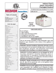
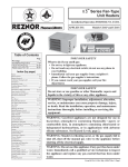
T874H,Q,W Multistage Thermostats and
Q674B,C,G,L Subbases
INSTALLATION INSTRUCTIONS
APPLICATION
The T874H,Q,W Multistage Thermostats provide 24 to 30
Vac control for heating and cooling systems as listed in
Table 1.
Table 1. Heating and Cooling Stages.
T874 Model
Ha
Q
W
Heating Stages
1
1
3
Cooling Stages
1
—
2
Stage
a Plus a changeover stage that operates with cooling.
When an LED lights, refer to this list for the meaning:
FILTER: clogged filter needs replacement.
EM. HT.: emergency heat is operating. The compressor
has failed, and the heat pump is not operating. The
LED lights when the homeowner places the system
switch in the EM. HT. position.
AUX. HT.: auxiliary heat is operating because the
weather is so cold that the heat pump alone cannot
handle the load.
SERVICE or CHECK: system needs to be checked.
See heating system instructions for specific
meaning.
LEDs are not field addable or replaceable.
RECYCLING NOTICE
The Q674B,C,G,L Subbases provide wiring terminals,
system and fan switching, and mounting bases for T874
Multistage Thermostats as listed in Table 2.
This control contains mercury in a sealed tube. Do
not place the control in the trash at the end of its
useful life.
Table 2. Switching Positions.
Switch Positions
Q674
Model
System
Fan
B
Heat-Off-Cool
Auto-On
C
Off-Auto
Auto-On
G
Off-Auto
None
L
Em Ht-Heat-Off-Cool
Auto-On
If this control is replacing a control that contains
mercury in a sealed tube, do not place your old
control in the trash.
Contact your local waste management authority for
instructions regarding the recycling and the proper
disposal of this control, or of an old control
containing mercury in a sealed tube.
OPERATION
On a two-stage or three-stage heat thermostat, the stages
of heat make sequentially as the temperature drops. Make
refers to the mercury switch initiating a call for heat or cool.
There are about 2°F (1°C) between the stages so that the
second stage makes only when the first stage can not
handle the load. About one degree later, the third stage
makes (T874W only). This degree difference is called the
interstage differential.
Select models include LEDs (light-emitting diodes). The
LED lights to indicate a problem with the system; refer to
the system manufacturer instructions.
Copyright © 1996 Honeywell Inc. •
• All Rights Reserved
INSTALLATION
When Installing this Product…
Read these instructions carefully. Failure to follow
them could damage the product or cause a hazardous condition.
Check the ratings given in the instructions and on
the product to make sure the product is suitable for
your application.
Installer must be a trained, experienced service
technician.
After installation is complete, check out product
operation as provided in these instructions.
X-XX UL
69-0087-6
T874H,Q,W MULTISTAGE THERMOSTATS AND Q674B,C,G,L SUBBASES
VERTICAL
OUTLET
1
BOX
CAUTION
1.
2.
3.
4.
5.
Disconnect the power supply to prevent
electrical shock or equipment damage.
Run the wires as close as possible to the
subbase. To prevent interference with the
thermostat linkage, keep the wire length to a
minimum. Push the excess wire back into the
hole, and plug the hole to prevent drafts from
affecting the thermostat operation.
Do not tighten the thermostat captive mounting screws to the point of damaging the
subbase threads.
Do not short across the coil terminals on the
relay. This can burn out the heat anticipator.
Never install more than one wire per terminal
unless a factory-supplied jumper with a spade
terminal is used.
MOUNTING
SCREWS (2)
COVER
PLATE 2
ADAPTER
RING 2
1
HORIZONTAL
OUTLET
BOX
THERMOSTAT
IMPORTANT
These thermostats are calibrated at the factory
by using subbases mounted at true level.
Inaccurate subbase leveling causes thermostat
control deviation.
THERMOSTAT
COVER
OL
CO
80
70
60
50
SUBBASE
80
70
60
T
HEA
50
SUBBASE
MOUNTING SCREWS (2)
Location
80
70
60
CAPTIVE
MOUNTING SCREWS (2)
Install the thermostat about 5 ft (1.5m) above the floor in
an area with good air circulation at average temperature.
50
1 NOT INCLUDED WITH UNIT.
Do not install the thermostat where it can be affected by:
— drafts, or dead spots behind doors and in corners.
— hot or cold air from ducts.
— radiant heat from sun or appliances.
— concealed pipes and chimneys.
— unheated (uncooled) areas behind the thermostat
such as an outside wall.
2 ACCESSORY PARTS AVAILABLE (193121A).
M6009
Fig. 1. Installation on vertical or horizontal outlet box.
SPIRIT LEVEL
TOP
MOUNTING
HOLES (2)
WIRING
TERMINAL
THERMOSTAT
CABLE OPENING
Mounting and Wiring the Subbase
Mount the subbase on a wall or horizontal outlet box. If
you mount it on a vertical outlet box, order Honeywell part
no. 193121A Adapter Assembly, which includes an
adapter ring with two screws, and a cover plate to cover
the marks on the wall.
All wiring must comply with local electrical codes and
ordinances. Follow the equipment manufacturer wiring
instructions, when available.
To install the subbase:
Prepare a hole for the thermostat wires at the
chosen location. Run wires to the location.
Pull about 6 in. (152 mm) of wire through the hole.
MOUNTING
HOLES (2)
TO SPRING FINGER
CONTACTS ON THE
THERMOSTAT
(UP TO 12)
M927
Fig. 2. Leveling subbase.
IMPORTANT
Use 18 gauge, color-coded thermostat cable for
proper wiring.
Connect the system wires to the subbase. See Fig.
4 through 9. A letter code for identification is
located near each terminal. The terminal barrier
permits straight or conventional wraparound wiring
connections. See Fig. 3. Either method is acceptable. Run the wires as close as possible to the
subbase, keeping the wire length to a minimum.
Push the excess wire back into the hole. Plug the
hole to prevent drafts.
When mounting the subbase on a vertical outlet box,
install an adapter ring with the two screws provided
with the adapter assembly. See Fig. 1.
Pull the wires through the cover plate (if used) and
the subbase wire opening. Secure the cover plate
and subbase with the two screws provided, but do
not fully tighten.
The subbase mounting slots provide for minor outof-level adjustments. Level the subbase by using a
spirit level and tightening the subbase mounting
screws. See Fig. 2.
69-0087—6
POST (2) FOR
MOUNTING
THERMOSTAT
IMPORTANT
An incorrectly leveled subbase causes the
temperature control to deviate from the setpoint.
2
T874H,Q,W MULTISTAGE THERMOSTATS AND Q674B,C,G,L SUBBASES
FOR STRAIGHT
INSERTION–
STRIP 5/16 in. (8 mm)
Mounting C815A Thermistor (T874W only)
The T874W is used with the C815A Thermistor mounted in
the outdoor section. Locate it in an area where it can
measure the true outdoor ambient temperature. Avoid
mounting the C815A in an area where it is exposed to high
temperatures or direct sunlight. Refer to heat pump
equipment instructions for proper mounting.
FOR WRAPAROUND–
STRIP 7/16 in. (11 mm)
BARRIER
SUBBASE TERMINAL SCREW
M928
Fig. 3. Wiring connections.
THERMOSTAT
SYSTEM COMPONENTS
SUBBASE
2
H1
ANTICIPATOR
FALL
Y1
COOL CHANGEOVER
VALVE
3
H1
FAN SWITCH
4
FAN RELAY
AUTO
G
ON
R
Y2
SYSTEM
SWITCH
OFF
8
COMPRESSOR
CONTACTOR
B
RISE
C1
ANTICIPATOR
9
AUTO
CO
10
2
RISE
C1
1
2
L2
L1
(HOT)
O
POWER SUPPLY. PROVIDE DISCONNECT MEANS
AND OVERLOAD PROTECTION AS REQUIRED.
1
X
SERVICE LED
(YELLOW)
COMPRESSOR
FAULT
C
SERVICE LED ON SELECT MODELS.
M3680A
Fig. 4. T874H/Q674C in heating-cooling system.
THERMOSTAT
SYSTEM COMPONENTS
SUBBASE
Y1
2
H1 ANTICIPATOR
H1
3
COOL CHANGEOVER
VALVE
FAN SWITCH
1
AUTO
FALL
4
G
L2
FAN RELAY
ON
R
L1
(HOT)
COMPRESSOR
CONTACTOR
Y2
RISE
B
CO
8
O
9
C1 ANTICIPATOR
10
SYSTEM
SWITCH
X
SERVICE
LED (YELLOW)
OFF
X1
AUTO
C1
1
RISE
C
FILTER LED (RED)
POWER SUPPLY. PROVIDE DISCONNECT MEANS
AND OVERLOAD PROTECTION AS REQUIRED.
24 VAC
X2
M5902
Fig. 5. T874H/Q674C in heating-cooling system with SERVICE LED and FILTER LED.
3
69-0087—6
T874H,Q,W MULTISTAGE THERMOSTATS AND Q674B,C,G,L SUBBASES
THERMOSTAT
SUBBASE
H1 ANTICIPATOR
SYSTEM COMPONENTS
1
W1
NO FAN
SWITCH
3
CHANGEOVER
RELAY
FALL
H1
B
4
W2
H2 ANTICIPATOR
FAN RELAY
6
G
FALL
H2
8
SYSTEM
SWITCH
OFF
9
AUTO
Y1
1
COMPRESSOR
CONTACTOR
C1
L2
R
1
C1 ANTICIPATOR
10
RISE
POWER SUPPLY. PROVIDE DISCONNECT MEANS AND
OVERLOAD PROTECTION AS REQUIRED.
Fig. 6. T874Q/Q674G for heating only system.
SUBBASE
THERMOSTAT
SYSTEM COMPONENTS
1
1
H1 ANTICIPATOR
FALL
C815A THERMISTOR
H1
H2 ANTICIPATOR
L1 (HOT)
R
2
L2
T
FAN SWITCH
FALL
3
AUTO
H3
4
H3 ANTICIPATOR
W1
HEAT RELAY 1
ON
W2
HEAT RELAY 2
5
FALL
H2
6
RESET HEATER
HEAT RELAY 3
SYSTEM
SWITCH
B
HEAT CHANGEOVER VALVE
HEAT
RISE
8
C1
W3
OFF
G
FAN RELAY
COOL
C1 ANTICIPATOR
10
O
11
Y2
COOL CHANGEOVER VALVE
C2 ANTICIPATOR
RISE
COMPRESSOR CONTACTOR 2
C2
1
Y1
POWER SUPPLY. PROVIDE DISCONNECT
MEANS AND OVERLOAD PROTECTION
AS REQUIRED.
COMPRESSOR CONTACTOR 1
M3674
Fig. 7. T874W/Q674B with outdoor reset in heating and cooling system.
69-0087—6
4
L1
(HOT)
M6008A
T874H,Q,W MULTISTAGE THERMOSTATS AND Q674B,C,G,L SUBBASES
THERMOSTAT
SUBBASE
SYSTEM COMPONENTS
L1
(HOT)
1
FALL
1
H1 ANTICIPATOR
L2
T
H1
2
C815A OD THERMISTOR
W3
H2
H2 ANTICIPATOR
FALL
AUX. HEAT RELAY
3
AUXILIARY
HEAT LED
(GREEN)
FAN SWITCH
H3 ANTICIPATOR
AUTO
4
G
ON
EMERGENCY
HEAT LED
(RED)
H3
FALL
U
5
FAN RELAY
R
E
6
RESET
COMPRESSOR
MONITOR
L
EM. HEAT RELAY
CHECK LED
(RED)
RISE
X
8
SYSTEM
SWITCH
B
C1
9
EM.HEAT
2
CHANGEOVER
RELAY (HEAT)
HEAT
C1 ANTICIPATOR
10
OFF
O
COOL
CHANGEOVER
RELAY (COOL)
COMPRESSOR
CONTACTOR 1
C2 ANTICIPATOR
RISE
C2
11
Y1
12
Y2
COMPRESSOR
CONTACTOR 2
1
POWER SUPPLY. PROVIDE DISCONNECT MEANS AND OVERLOAD PROTECTION AS REQUIRED.
2
CONNECT CHANGEOVER RELAY TO 'O' TERMINAL FOR CHANGEOVER IN COOLING OR TO 'B' TERMINAL FOR CHANGEOVER IN HEATING.
M156A
Fig. 8. T874W/Q674L for three-stage heat and two-stage cool with outdoor reset and compressor monitor.
5
69-0087—6
T874H,Q,W MULTISTAGE THERMOSTATS AND Q674B,C,G,L SUBBASES
THERMOSTAT
SUBBASE
SYSTEM COMPONENTS
1
FALL
H1 ANTICIPATOR
T
H1
2
C815A OUTDOOR
THERMISTOR
H2
W3
H2 ANTICIPATOR
FALL
AUX. HT. RELAY
3
AUX. HEAT
LED (GREEN)
FAN SWITCH
AUTO
H3 ANTICIPATOR
4
G
ON
FAN RELAY
H3
L1
(HOT)
L2
1
R
FALL
5
EM. HEAT
LED (RED)
E
6
EM. HT. RELAY
RESET
X1
CHECK LED
(YELLOW)
C
CHANGEOVER
RELAY (HEAT)
RISE
8
C1
SYSTEM
SWITCH
CHANGEOVER
RELAY (COOL)
EM.HT.
9
HEAT
C1 ANTICIPATOR
2
B
O
OFF
10
X2
COOL
COMPRESSOR
CONTACTOR 1
C2 ANTICIPATOR
RISE
C2
11
Y1
12
Y2
COMPRESSOR
CONTACTOR 2
1
POWER SUPPLY. PROVIDE DISCONNECT MEANS AND OVERLOAD PROTECTION AS REQUIRED.
2
CONNECT CHANGEOVER RELAY TO 'O' TERMINAL FOR CHANGEOVER IN COOLING OR TO 'B' TERMINAL FOR CHANGEOVER IN HEATING.
M6999
Fig. 9. T874W/Q674L for three-stage heat and two-stage cool with outdoor reset.
T874Q only: Set the heat anticipator indicators to
the respective current setting for each stage. See
Setting the Heat Anticipator section. T874H and
T874W have fixed anticipation; the settings are
preselected and cannot be adjusted.
Note the tabs along the top inside edge of the
thermostat base. The tabs fit into the subbase
notches. Mount the thermostat base on the subbase
and tighten the captive mounting screws. See Fig. 1.
Place the upper edge of the thermostat cover on the
thermostat base and swing the cover downward until
it engages with the cover clip on the base.
Mounting the Thermostat
Remove the thermostat cover by pulling the bottom
edge of the cover upward until it snaps free of the
cover clip.
NOTE: The cover is hinged at the top and must be
removed by pulling up at the bottom.
Carefully remove and discard the polystyrene
packing insert that protects the mercury switches
during shipment.
Turn over the thermostat base and note the spring
fingers that engage the subbase contacts. Make
sure the spring fingers are not bent flat, preventing
proper electrical contact with the subbase.
69-0087—6
6
T874H,Q,W MULTISTAGE THERMOSTATS AND Q674B,C,G,L SUBBASES
SETTING
THERMISTOR RESISTANCE
Setting the Heat Anticipator (T874Q Only)
Set each heat anticipator to match its primary control
current draw. If the primary control nameplate has no
rating or if further adjustment is necessary, use the
following procedure to determine the current draw of each
stage. (Measure the current draw of each heating stage
with the thermostat removed and the power on.)
Connect an ac ammeter of appropriate range
between the heating terminals of the subbase as
follows:
Stage 1: between W1 and RH or R.
Stage 2: between W2 and R.
Move the system switch to AUTO (if applicable).
After one minute, read the ammeter and record the
reading.
After mounting the thermostat, set the adjustable
heat anticipator(s) to match the respective
reading(s) measured in step .
4600
4400
4200
4000
3800
3600
3400
3200
3000
2800
2600
2400
2200
2000
1800
1600
1400
1200
1000
800
600
400
200
0
C815A THERMISTOR RESISTANCE
R = 400 ohms ± 10% AT 77°F (25°C)
-20
0
20
40
60
80
100
120
TEMPERATURE OF THERMISTOR (°F)
140
M1590A
Fig. 10 Thermistor resistance chart.
The proper thermistor operation must be verified to assure
the correct operation of the thermostat. Check the
thermistor operation as follows:
Disconnect the T wire on the subbase.
Use an ohmmeter to measure resistance between
the T wire and the transformer common.
Take the outdoor temperature at thermistor location
and find the correct thermistor resistance on the
chart in Fig. 10.
If the resistance measured in step and the
calculated resistance in step vary by more than
15 percent, the thermistor requires replacement.
Contact the installing dealer for the packaged
replacement outdoor thermistor.
Temperature Setting
Move the heating and cooling levers to the desired
positions. The minimum differential between the heating
and cooling setpoints is 3°F (1.7°C), which means the
setting levers cannot be set closer together than 3°F
(1.7°C) (5° F [2.8°C] for T874W).
Subbase Setting
System switching positions control thermostat operation as
follows:
OFF: Both the heating and cooling systems are off. If
the fan switch is in the AUTO position, the cooling
fan is also off.
AUTO: Thermostat automatically changes between the
heat and cool modes, depending on the indoor
temperature.
HEAT: Heating system is controlled by the thermostat.
Cooling system is off.
EM. HT.: Emergency heat relay is energized. The
cooling system is off. When the compressor has
failed and the heat pump is not operating, switch to
the EM. HT. position.
CHECKOUT
Heating
Move the system switch on the Q674 Subbase to HEAT or
AUTO. Move the heating lever on the T874 about 10°F
(6°C) above room temperature. Both stages of heating
start and the fan runs after a short delay. Move the heating
lever about 10°F (6°C) below room temperature. The
heating equipment shuts off, and the fan runs for a short
time, and then shuts off.
Fan switching positions control fan operation as follows
(Q674B,C, or L):
ON: Fan operates continuously.
AUTO: Fan operates with cooling equipment as
controlled by the thermostat or with the heating
equipment as controlled by the plenum switch.
Cooling
To switch positions, use thumb and index finger to slide
the lever to the desired position. The switch lever must
stop in detent over the desired function indicator mark for
proper circuit operation.
Move the system switch on the Q674 Subbase to COOL
or AUTO. Move the cooling lever on the T874 Thermostat
about 10°F (6°C) below room temperature. The cooling
equipment and fan start. Move the cooling lever about
10°F (6°C) above room temperature. The cooling equipment and fan stop.
C815 Outdoor Reset Thermistor (T874W only)
Emergency Heat
Move the system switch to EM. HT. The EM. HT. LED
comes on. Move the heating lever about 10°F (6°C) above
room temperature. The electric strip heater(s) comes on.
Move the heating lever about 10°F (6°C) below room
temperature. The electric strip heater de-energizes. The
EM. HT. LED remains on until the system switch is moved
to another postion.
The T874W is used with a C815 Thermistor mounted in
the outdoor section. The thermistor must be used; if not,
thermostat performance will deviate radically from proper
operation.
7
69-0087—6
T874H,Q,W MULTISTAGE THERMOSTATS AND Q674B,C,G,L SUBBASES
Fan (Select Models)
NOTE: Hand heat offsets the thermometer
reading. After making each adjustment,
wait 10 or 15 minutes for the thermometer
to stabilize before comparing.
Move the subbase system switch to OFF, and the fan
switch to ON. The fan runs continuously. When the fan
switch is in the AUTO position, the fan operation is
controlled by the heating or cooling system.
CALIBRATION
Thermostat
T874 Thermostats are accurately calibrated at the factory.
They do not have provision for field calibration.
Thermometer
Remove the thermostat cover by pulling up from the
bottom of the cover until it clears the locking springs.
Set the cover on a table near an accurate thermometer.
After allowing 10 or 15 minutes for stabilization,
compare the readings. If they are the same, replace
the cover and put the system into operation. If they
are different, recalibrate the thermostat thermometer; see step Insert a small screwdriver into the thermometer shaft
and turn it until the thermometers read the same.
See Fig. 11. When the thermometer is calibrated,
replace the cover and place the system into
operation.
Automation and Control Solutions
Honeywell Internationl, Inc.
1985 Douglas Drive North
Golden Valley, MN 55422
69-0087—6 C.H. Rev. 9-96
M5070
Fig. 11. Thermometer calibration.
Honeywell Limited-Honeywell Limitée
35 Dynamic Drive
Scarborough, Ontario
M1V 4Z9
8
Printed in U.S.A. on recycled
paper containing at least 10%
post-consumer paper fibers.
www.honeywell.com