1
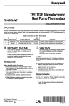
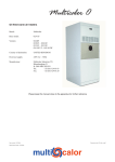
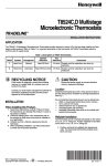
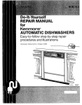
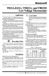
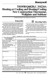
Q539A, H and J Subbases Installation Instruction for the Trained Service Technician. Application Q539 Subbases provide cooling anticipators, and mounting for T87F Thermostats. Q539 Subbases also provide system and fan switching for heating, cooling, and heating-cooling thermostats. For subbase specifications, refer to Tables 1 and 2. TABLE 1—SUBBASE SPECIFICATIONS. System Switch Model Description Fan Switch See Fig. Terminals Q539A provides system and fan switching and cooling anticipator for heating cooling systems. Includes indicator LOCKOUT LED for use in oil burner systems. HEATOFFCOOL AUTO-ON RH -RC-W-Y-G-X 3 Q539H provides fan switching with Z terminal for low voltage fan switch to control fan in AUTO position. NONE AUTO-ON R-W-Y-G-X-Z 4 Q539J provides system switching for control of heating and cooling for heat pump and electric heating. Auto fan operates through fan relay on both heating and cooling. HEATOFFCOOL AUTO-ON R-W-Y-G-X-P-O-B 5 TABLE 2—TERMINAL DESIGNATIONS. Terminal R RCa RH b W Y Bc Od G Xe P Z Connection Transformer. Cooling Transformer. Heating Transformer. Heating Relay or Valve Coil. Cooling Contactor Coil. Heating Damper Motor or Changeover Valve (if used). Cooling Damper Motor or Changeover Valve (if used). Fan Relay Coil. Clogged Filter Switch or Lockout Switch (primary control). Heat Pump Contactor Coil. Q539H low voltage fan switch for control of fan relay in AUTO position for both heating and cooling control. a Cooling transformer in systems with separate heating and cooling circuits. Heating transformer in systems with isolated heating and cooling circuits. c Circuit only completed between R and B with system switch in HEAT position. d Circuit only completed between R and O with system switch in COOL position. e Only available on subbases with indicator LEDs. b ®U.S. Registered Trademark Copyright © 2002 Honeywell • • All Rights Reserved M3375 Mercury Notice This control contains mercury in a sealed tube. Do not place control in the trash at the end of its useful life. If this control is replacing a control that contains mer cury in a sealed tube, do not place your old control in the trash. Contact your local waste management authority for instructions regarding recycling and the proper disposal of this control, or of an old control containing mercury in a sealed tube. Installation WHEN INSTALLING THIS PRODUCT… 1. Read these instructions carefully. Failure to follow instructions can damage product or cause a hazardous condition. 2. Check ratings given in instructions and on product to make sure product is suitable for your application. 3. Make sure installer is a trained, experienced service technician. 4. After completing installation check out product opera tion as provided in these instructions. LOCATION Locate the subbase about 5 ft (1.5m) above the floor in an area with good air circulation at average temperature. 95-6486-9 Do not mount the subbase where it may be affected by: — drafts or dead spots behind doors or in corners. — hot or cold air from ducts. — radiant heat from the sun, fireplaces, or appliances. — concealed pipes and chimneys. — unheated (uncooled) areas such as an outside wall. Fig. 1—Level Q539 using a spirit level . SPIRIT LEVEL LEVELING POSTS (2) CAUTION • Disconnect power supply to prevent electri cal shock or equipment damage. • Do not short across coil terminals on relay, this can burn out the thermostat heat anticipator. • Do not overtighten captive mounting screws because damage to subbase threads can result. OPENING FOR THERMOSTAT WIRING MOUNTING SLOTS M3319A MOUNTING AND WIRING Disconnect power supply before beginning installation to prevent electrical shock or equipment damage. All wiring must comply with local codes and ordinances. 1. In replacement applications, check the existing sub base wires for cracked or frayed insulation. Replace any wires in poor condition. If the wire is plastered into the wall, make a hole next to the wires and loosen the wires so that the wires can be pushed back into the wall later. 2. In new installations, run wiring (if necessary) to the subbase location. Fig. 2—Barrier configuration. FOR STRAIGHT INSERTION– STRIP 5/16 in. (8 mm) FOR WRAPAROUND– STRIP 7/16 in. (11 mm) BARRIER M8831 SUBBASE TERMINAL SCREW IMPORTANT: To prevent interference with the thermostat linkage, keep wire length to a minimum and run wires as close as possible to the subbase. Fig. 3—Typical hookup for Q539A in heating cooling application with remote lockout indication. 3. Connect the wires to the terminals inside the subbase. Refer to equipment manufacturer instructions for Q539 wiring diagrams. If not available, refer to Fig. 1 through 5. 4. Push excess wire back through the hole and plug any opening with insulation to prevent drafts that can affect performance. 5. Loosely fasten the thermostat subbase to the wall with a screw through the left mounting hole. Adjust the subbase so it is approximately level and start the second screw through the right mounting slot. Do not tighten. 6. Level the thermostat subbase using a spirit level as shown in Fig. 1. 7. Tighten mounting screws. Q539A/T87F INTERNAL SCHEMATIC T87F FIXED COOL ANTICIPATOR TEMP. FALL R1 ADJUSTABLE HEAT ANTICIPATOR W1 Y1 FAN AUTO ON COOL HEAT OFF COOL OFF LOCKOUT HEAT INDICATOR LIGHT IMPORTANT: An incorrectly leveled subbase will cause the temperature control to deviate from setpoint. X RH W Y 8. Mount and wire the thermostat to the thermostat sub base using the equipment manufacturer’s instructions. G RC FAN RELAY SWITCH HEATING CONTROL HEATING TRANSFORMER COOLING CONTROL COOLING TRANSFORMER 1 1 L2 L1 (HOT) 1 L2 L1 (HOT) POWER SUPPLY. PROVIDE DISCONNECT MEANS AND OVERLOAD PROTECTION AS REQUIRED. M8832 95-6486—9 2 Settings Fig. 5—Typical hookup for Q539J in heating cooling applications. Fan relay operates automatically on heat or cool with fan in AUTO position SUBBASE SETTING The subbase switching positions control the system operation as described below. SYSTEM SWITCH (some subbases do not have all of the following functions): COOL—cooling system is automatically controlled by the thermostat. Heating system is off. OFF—both the heating and cooling systems are off. If the fan switch is at AUTO position, the cooling fan is also off. HEAT—heating system is automatically controlled by the thermostat. Cooling system is off. FAN SWITCH: ON—fan operates continuously. AUTO—fan operates with cooling equipment as con trolled by the thermostat or with the heating equip ment as controlled by the plenum switch. To move the subbase switches to the desired control positions, use thumb and index finger to slide lever. Stop lever must stop over desired function indicator position for proper circuit operation. Q539J/T87F INTERNAL SCHEMATIC T87F R1 TEMP. FALL FILTER LIGHT ADJUSTABLE HEAT ANTICIPATOR W1 Y1 FAN OFF ON COOL HEAT OFF COOL AUTO HEAT 1 X W Y ELECTRIC HEAT RELAY CLOGGED FILTER SWITCH OR COOLING PANEL CONNECTION Fig. 4—Typical hookup for Q539H in heating cooling application with remote switching required to select heating or cooling and to provide automatic fan operation. B R G O HEATING DAMPER MOTOR P FAN RELAY 2 COMPRESSOR RELAY COOLING DAMPER MOTOR Q539H/T87F INTERNAL SCHEMATIC 3 T87F L2 TEMP. FALL R1 FILTER LIGHT ADJUSTABLE HEAT ANTICIPATOR X TERMINAL IS USED ON Q539 MODELS WITH FACTORYINSTALLED MALFUNCTION LIGHT. 2 WITH NO O TERMONAL LOAD, THERMOSTAT CURRENT DURING HEATING CYCLE VARIES DEPENDING ON WHETHER FAN SWITCH IS IN THE ON OR AUTO POSITION. HEATER SHOULD BE SET FOR COMBINED CURRENT LEVEL OF HEAT RELAY AND FAN RELAY COILS. WITH O TERMINAL LOAD, SET THERMOSTAT HEAT ANTICIPATOR TO ITS MAXIMUM SETTING. (LIMIT THE THERMOSTAT HEATING LOAD CURRENT TO 0.8 AMPS TO ASSURE GOOD PERFORMANCE.) 3 POWER SUPPLY. PROVIDE DISCONNECT MEANS AND OVERLOAD PROTECTION AS REQUIRED. Y1 W1 FAN AUTO X ON 1 W REMOTE SYSTEM SWITCH Y Z G R M8834 HEAT FAN RELAY Checkout COOL CLOGGED FILTER SWITCH OR COOLING PANEL CONNECTION L1 (HOT) 1 HEATING RELAY OR VALVE COIL COOLING CONTACTOR COIL When installation is complete, turn on power supply and check system operation. EXTERNAL SWITCHING FOR AUTO FAN 1 X TERMINAL IS USED ON Q539 MODELS WITH FACTORY-INSTALLED MALFUNCTION LIGHT. 2 POWER SUPPLY. PROVIDE DISCONNECT MEANS AND OVERLOAD PROTECTION AS REQUIRED. HEATING Move the system switch on the Q539 to HEAT and the fan switch to AUTO. Move the heating setpoint dial to about 6AC (10AF) above room temperature. Heating equipment should start and the fan should run. Change the setpoint to about 6AC (10AF) below the room temperature. The heating equipment and fan should shut off. 2 L2 L1 (HOT) NOTE: In heat pump applications, a minimum off-timer provides a five-minute time delay before starting com pressor when the thermostat last turned off the compres sor, or when the system first received power. This delay prevents compressor short cycling. M8833 3 95-6486—9 COOLING CAUTION If outside air or heat exchange medium (water) is below 10AC (50AF), do not operate cooling. Move the system switch on the Q539 to COOL and the fan switch to AUTO. Move the cooling setpoint dial to about 6AC (10AF) below room temperature. Cooling equipment should start and the fan should run. Change the setpoint to about 6AC (10AF) above the room temperature. The cooling equipment and fan should shut off. FAN Move the subbase switch to OFF and the fan switch to ON. The fan should run continuously. Move the fan switch to AUTO. In this position, fan operation is controlled by the heating or cooling system control circuit. Operate the entire system one complete cycle with switches in each position before leaving installation. Turn thermostat dial to the desired setting and set the system and fan switches. Automation and Control Solutions Honeywell Honeywell Limited—Honeywell Limitée 1985 Douglas Drive North 35 Dynamic Drive Golden Valley, MN 55422 Scarborough, Ontario M1V 4Z9 95-6486–9 G.H. Rev. 8-02 Printed in U.S.A. on recycled paper containing at least 10% post-consumer paper fibers. www.honeywell.com/yourhome