1
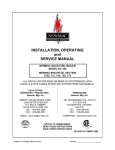
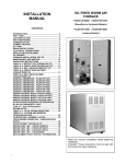
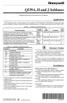
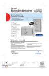
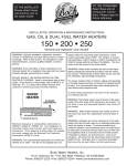
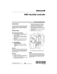
T87F Thermostats
PRODUCT DATA
FEATURES
• For 24 Vac to 30 Vac control of heating or cooling
systems.
• Thermostat cover ring may be painted to match room
decor.
• Knurled dial provides easy setpoint adjustment.
T87F Easy-toSee™ Round
Model
T87F Designer
Model
T87F Standard
Model
• Separate temperature setting and thermometer scale
located on face of thermostat.
• T87F distinctive style makes an attractive addition to
almost any decor.
• Enhanced setpoint visibility model available for the
visually impaired.
APPLICATION
T87F Thermostats provide temperature control for residential
heating, cooling, or heating-cooling systems. The T87F is
designed with a dustproof spdt mercury switch, an adjustable
heat anticipator and a concealed wallplate for 2-wire heating
hookups. The Tradeline® T87F wallplate is designed for 2wire heating or cooling, 3-wire spdt heating (series 20), or 3wire spdt heating-cooling with remote switching. The wallplate
also provides cooling anticipation.
The Q539 Subbase may be added for system and fan
switching. The Q539 Subbase also provides cooling
anticipation.
Contents
Application.........................................................................1
Features ............................................................................1
Specifications ....................................................................2
Ordering Information .........................................................2
Installation .........................................................................3
Wiring ................................................................................4
Settings and Checkout ......................................................7
Operation...........................................................................8
Recalibration .....................................................................8
® U.S. Registered Trademark
Copyright © 2002 Honeywell • All Rights Reserved
60-2222-3
T87F THERMOSTATS
SPECIFICATIONS
IMPORTANT
This product is tested and calibrated under closely
controlled conditions and some minor differences in
performance can be expected if those conditions are
changed. The specifications in this publication do not
include normal manufacturing tolerances; therefore,
an individual unit may not exactly match the listed
specifications.
T87F Heating, Cooling, or Heating-Cooling Thermostat. Thermostat includes 104456B Wallplate for heating only systems. Order Q539 Subbase for heating-cooling.
Electrical Ratings: 1.5A at 30 Vac.
Heat Anticipator: Adjustable 0.1 to 1.2A.
Tradeline® Models:
For use in series 80 heating, cooling, or heating-cooling
circuit, or for use in series 20 (spdt) heating only circuit.
Tradeline® specifications are the same as those of standard
models, except as follows:
T87F Heating, Cooling, or Heating-Cooling Thermostat.
T87F Enhanced Setpoint Visibility Model for the visually
impaired.
T87F models that meet Department of Defense (DoD) Manual
4270.1-M specifications.
Model for heating. control. Locking cover, without thermometer, 72°F (22°C) maximum heat.
Model for cooling control, locking cover, without thermometer,
78°F 26°C) minimum cool.
T87F with locking cover, range stops 35°F to 65°F (2°C to
18°C) range.
Temperature Ratings:
Setting Range:
Most models: 40°F to 90°F (4°C to 32°C).
Models with positive Off: 50°F to 90°F (10°C to 32°C).
Cooling Anticipator: 0 to 1.5A, 24 Vac to 30 Vac.
Temperature Ratings: 50°F to 100°F (10°C to 38°C).
Switching Action: Dust-free spdt mercury switch.
Temperature Sensing: Coiled bimetal.
Dimensions:
T87F: 3-1/4 in. (82.5 mm) diameter, 1-1/2 in. (38 mm) deep.
With 137421 Wallplate: 3-11/16 in. (93.5 mm) diameter, 1-3/4
in. (44.5 mm) deep.
With Q539 Subbase: 3-11/16 in. (93.5 mm) diameter, 1-3/4 in.
(44.5 mm) deep.
Mounting: Thermostat mounts on furnished wallplate, or subbase (order separately).
Finish: Premier White® or taupe.
Mounting:
T87F (without positive Off) furnished with 137421A Wallplate.
T87F (with positive Off) furnished with 137421B Wallplate.
Both wallplates suitable for controlling 2-wire spst heating or
cooling, 3-wire spdt heating-cooling, or 3-wire spdt series
20 heating systems.
Additional Tradeline® Features:
Cover ring included for covering old thermostat marks or for
mounting T87F on outlet box.
137421 Wallplate extends beyond thermostat for trim appearance (198170A Wallplate for Designer Models).
Tradeline® pack with cross reference label and special
instruction sheet.
60-2222—3
Standard Models:
2
Optional Specifications:
Positive Off Models (specify heating or cooling):
60°F to 100°F (16°C to 38°C) or 50°F to 90°F (10°C to
32°C) range.
Locking Cover and Range Stop Models:
60°F to 90°F (16°C to 32°C).
45°F to 75°F (7°C to 24°C) range, 68°F marked on scale.
Scale Range Models:
40°F to 90°F (4°C to 32°C).
45°F to 75°F (7°C to 24°C).
5°C to 30°C (67°F to 112°F).
10°C to 30°C (67°F to 86°F).
10°C to 35°C (67°F to 95°F).
T87F THERMOSTATS
Accessories:
Q539 Subbases—provide system and fan switching and cooling anticipation (unless otherwise specified) for T87F heating, cooling and heating-cooling thermostats.
TG587F1008 Thermostat Guard Key Lock Cover with window.
TG587F1016 Thermostat Guard Key Lock cover without
window.
104456B Two terminal heat only T87 Wallplate.
137421AE-T87 Taupe Wallplate with positive Off.
137421K-T87 Taupe Wallplate without positive Off.
137421R-T87 White Wallplate.
198170A Designer Beige Adapter Kit.
198172 Cover Ring for T87 Designer Beige models.
199933 Cover Ring for Taupe T87 models.
114855-00029 Cover Ring for Gold T87 models.
137421A-T87 Gold Wallplate without positive Off.
137421B-T87 Gold Wallplate with positive Off.
221886A Easy-to-Use™ Clear Ring. Durable plastic ring
snaps on Easy-to-See models.
202687A Premier White® Adapter Kit includes 6 in. cover
assembly and adapter ring to mount on outlet box or cover
marks from old thermostats.
32005439-001 Taupe Adapter Kit includes 6 in. cover assembly and adapter ring to mount on outlet box or cover marks
from old thermostat.
MERCURY NOTICE
If this control is replacing a control that contains
mercury in a sealed tube, do not place your old control
in the trash. Dispose of properly.
Contact your local waste management authority for
instructions regarding recycling and the proper
disposal of an old control.
Location
Locate the thermostat about 5 ft (1.5m) above the floor in an
area with good air circulation at average temperature.
Do not install the thermostat where it can be affected by:
— drafts, or dead spots behind doors and in corners.
— hot or cold air from ducts.
— radiant heat from sun or appliances.
— concealed pipes and chimneys.
— unheated (uncooled) areas such as an outside wall behind
the thermostat.
This thermostat is a precision instrument and was carefully
adjusted at the factory. Handle it carefully.
Mount Wallplate or Subbase
IMPORTANT
Use a spirit level to accurately level the wallplate or
subbase as shown in Fig. 1. Inaccurate leveling may
cause the thermostat to deviate from setpoint.
When using the T87F with a Q539 Subbase, follow
the mounting and wiring instructions for the subbase.
IMPORTANT
Before mounting the thermostat, see Setting and
Checkout section, Heat Anticipator Adjustment subsection.
CAUTION
1.
Voltage Hazard.
Can cause electrical shock or equipment damage.
Disconnect power before beginning installation.
CAUTION
Equipment Damage Hazard.
Improper installation can burn out thermostat heat
anticipator.
On systems using a low voltage gas valve, do not
apply a jumper across the valve coil terminals.
Read these instructions carefully. Failure to follow them
could cause a hazardous condition.
Check the ratings given in the instructions and on the
product to make sure the product is suitable for your
application.
3
Place the cover ring on the wall at the desired location
with the cable entrance holes to the left.
NOTE: If an outlet box is used, place the cable entrance
holes toward the bottom. The side showing MADE IN
U.S.A. must be against the wall.
2.
3.
4.
5.
When Installing this Product. . .
2.
4.
Installer must be a trained experienced service technician.
After installation is complete, check out product operation as provided in these instructions.
Use the cover ring (if desired), adapter plate (if needed),
wallplate or subbase, T87F and screws as shown in Fig. 2 and
3.
INSTALLATION
1.
3.
6.
Pull the thermostat cable through the entrance hole of
the cover ring and the entrance hole of the wallplate or
subbase and adapter plate (if used).
Fasten the cover ring, adapter plate (if used), and the
wallplate or subbase.
Level the wallplate as shown in Fig. 1 and tighten the
screws.
After wiring the subbase or wallplate, plug the hole to
prevent interior wall drafts from affecting the thermostat.
Align the thermostat over the wallplate and tighten the
three captive mounting screws.
60-2222—3
T87F THERMOSTATS
THERMOSTAT
CABLE
ENTRANCE
HOLES
104456B WALLPLATE
SPIRIT LEVEL
OUTLET BOX
MOUNTING
SLOTS
BE SURE WALL
HOLE IS
PLUGGED
TERMINAL
SCREWS
MOUNTING
SLOTS
137421
WALLPLATE
137421A,B,D WALLPLATE
SPIRIT
LEVEL
1
127293
COVER RING
LEVELING
POSTS (2)
T87F
OPENING FOR
THERMOSTAT
WIRING
MOUNTING
SLOTS
CAPTIVE
MOUNTING
SCREWS (3)
Q539 SUBBASE 2
1
IF OUTLET BOX IS HORIZONTAL, MOUNT COVER RING IN POSITION
SHOWN, BUT FASTEN WITH SCREWS THROUGH "A".
2
USE 137421A,B WALLPLATE FOR HEAT OR COOL APPLICATIONS
WITHOUT SWITCHING. USE Q539 SUBBASE FOR HEAT OR COOL
APPLICATIONS WITH SWITCHING.
M20774
M20772
Fig. 3. Mount T87F, Q539 Subbase or 137421 Wallplate to
outlet box.
Fig. 1. Level 104456B, 137421A,B,D Wallplates.
WIRING
104456B WALLPLATE
THERMOSTAT
CABLE OPENING
CAUTION
T87F
Voltage Hazard.
Can cause electrical shock or equipment damage.
Disconnect power before beginning installation.
MOUNTING
SLOTS (4)
IMPORTANT
All wiring must comply with local electrical codes and
ordinances.
THERMOSTAT
COVER RING
The T87F may be used in most 2- or 3-wire, spst or spdt, 24
Vac to 30 Vac heating systems controlled by a low voltage
thermostat. The following wiring diagrams represent typical
applications.
THERMOSTAT
COVER RING
M20773
Fig. 2. Mount T87F, 104456B Wallplate.
60-2222—3
4
T87F THERMOSTATS
T87F
T87F
TEMPERATURE FALL
TEMPERATURE FALL
THERMOSTAT
THERMOSTAT
Y1
Y1
1
1
W1
R1
ADJUSTABLE
HEAT
ANTICIPATOR
W1
3
R1
ADJUSTABLE
3
HEAT
ANTICIPATOR
104456B
WALLPLATE
R
2
137421A,B
WALLPLATE
W
R
Y
2
COOLING
ANTICIPATOR
TO SYSTEM CONNECTIONS
W
TO SYSTEM CONNECTIONS
HEATING ONLY THERMOSTAT
TRADELINE THERMOSTAT
1
MODEL WITH POSITIVE OFF SWITCH OPENS THE THERMOSTAT CIRCUIT
WHEN SETPOINT DIAL IS MOVED TO THE OFF POSITION.
1
MODEL WITH POSITIVE OFF SWITCH OPENS THE THERMOSTAT
CIRCUIT WHEN SETPOINT DIAL IS MOVED TO THE OFF POSITION.
2
MAKE SYSTEM WIRING CONNECTIONS TO TERMINALS ON 104456B
WALLPLATE.
2
MAKE SYSTEM WIRING CONNECTIONS TO TERMINALS ON 137421A,B
WALLPLATE.
3
R1, W1 TERMINALS ON THERMOSTAT ARE DIRECTLY CONNECTED TO
R, W TERMINALS ON WALLPLATE WHEN THERMOSTAT IS MOUNTED
ON WALLPLATE.
3
R1, W1, Y1 TERMINALS ON THERMOSTAT ARE DIRECTLY CONNECTED TO
R, W, Y TERMINALS ON WALLPLATE WHEN THERMOSTAT IS MOUNTED
ON WALLPLATE.
M18011
M20776
Fig. 4. Internal wiring for T87F Heating Only Thermostat.
Fig. 6. Internal wiring for Tradeline® T87F Thermostat.
T87F
L1
(HOT)
TEMPERATURE RISE
THERMOSTAT
RY
THERMOSTAT
COOLING
CONTACTOR COIL
Y1
1
1 POWER SUPPLY. PROVIDE DISCONNECT MEANS AND
OVERLOAD PROTECTION AS REQUIRED.
W1
R1
L2 1
M6101
Fig. 7. Typical wiring for T87F used as a Cooling Only
Thermostat.
COOLING 3
ANTICIPATOR
137421D
WALLPLATE
R
Y
2
TO SYSTEM CONNECTIONS
COOLING ONLY THERMOSTAT
1
MODEL WITH POSITIVE OFF SWITCH OPENS THE THERMOSTAT
CIRCUIT WHEN SETPOINT DIAL IS MOVED TO THE OFF POSITION.
2
MAKE SYSTEM WIRING CONNECTIONS TO TERMINALS ON 137421D
WALLPLATE.
3
R1, W1 TERMINALS ON THERMOSTAT ARE DIRECTLY CONNECTED TO
R, Y TERMINALS ON WALLPLATE WHEN THERMOSTAT IS MOUNTED
ON WALLPLATE.
M20775
Fig. 5. Internal wiring for T87F Cooling Only Thermostat.
5
60-2222—3
T87F THERMOSTATS
COMBINATION FAN
AND LIMIT CONTROL
TRANSFORMER
COOL
POSITION
THERMOSTAT
L1
(HOT)
1
R Y
W
FAN
MOTOR
L2
BURNER
MOTOR
L1 1
(HOT)
L2
REMOTE
CHANGEOVER
SWITCH
COOLING
CONTACTOR COIL
HEAT
POSITION
3
OIL VALVE
OIL PRIMARY
ISOLATING
RELAY
IGNITION
THERMOSTAT
Y
R
R8184G
T
2
W
WHITE
1
T
POWER SUPPLY. PROVIDE DISCONNECT MEANS AND OVERLOAD
PROTECTION AS REQUIRED.
M6104A
ORANGE
F
Fig. 10. T87F in heating-cooling application with remote
mounted system changeover switch. (Use Q539 Subbase
for switching at thermostat location.)
F
BLACK
CAD CELL
1
POWER SUPPLY. PROVIDE DISCONNECT MEANS AND
OVERLOAD PROTECTION AS REQUIRED.
2
R8184 PROTECTORELAY OIL PRIMARY CONTAINS
INTERNAL TRANSFORMER
3
CONNECT OIL VALVE, IF APPLICABLE.
To Replace a Series 10 Thermostat
To adapt the T87F to a series 10 three-wire heating system:
1. Connect the wires from the thermostat (R and W) to the
terminals on the three-wire primary (B and W). See Fig.
11 and 12.
M6105A
NOTES:
—
Fig. 8. T87F in typical oil heating system.
THERMOSTAT
R
LIMIT
W
GAS VALVE
1
COMBINATION FAN AND
LIGHT CONTROLLER
TH
TR
TH
TR
TRANSFORMER
Some three-wire controls manufactured by other
companies cannot be satisfactorily operated by a
two-wire thermostat.
Before connecting the T87F to a three-wire control, consult the manufacturer.
Some Honeywell series 10 relays require an R-B
jumper (see Fig. 11). These relays are:
R114A,B
R125
R117
R187A1,A4
R116
R126
R178
R190B1,B8
R117
R161
R180
Relays or valves that do not require a jumper may
retain a three-wire, low limit control as shown in
Fig. 11. If the jumper is required, a two-wire control must be used.
A three-wire, open contact, high-limit control
requires a jumper as shown in Fig. 12.
—
FAN
—
L1 1
(HOT)
L2
—
FAN
MOTOR
POWER SUPPLY. PROVIDE DISCONNECT MEANS AND
OVERLOAD PROTECTION AS REQUIRED.
M6103
—
Fig. 9. T87F in typical gas heating system.
JUMPER
MAY BE
REQUIRED
2-WIRE LOW LIMIT
OPERATING CONTROL
R
B
T87F
R
W
Y
W
SERIES 10
RELAY OR VALVE
R
R
B
B
W
W
3-WIRE LOW-LIMIT OPERATING
CONTROL MAY BE RETAINED
ONLY IF R-B JUMPER IS NOT
REQUIRED ON RELAY OR VALVE
M20777
Fig. 11. T87F (replacing a series 10 thermostat) connected
to a 2- or 3-wire low limit control.
60-2222—3
6
T87F THERMOSTATS
LOW LIMIT
OPERATING CONTROL
JUMPER
B
B
W
W
R
Y
W
R
R
SETTINGS AND CHECKOUT
TO THERMOSTAT
CONNECTIONS ON
SERIES 10 VALVE
AT BURNER
T87F
SERIES 10 OPEN
CIRCUIT HIGH LIMIT
Temperature Selection
To select the desired temperature, turn the transparent dial
until the desired point on the setting scale (top scale) is in line
with the pointer.
M6102
Fig. 12. T87F (replacing a series 10 thermostat) connected
to a 3-wire open contact, high-limit control.
To Replace a Series 20 Thermostat
Tradeline® T87F Thermostats directly replace series 20 spdt
thermostats, or thermostats in heating installations that
require contact on both a rise and fall in temperature (see Fig.
13).
On models with range stops the temperature range may be
limited at either extreme. The left stop is for the low extreme,
the right stop for the high extreme (see Fig. 14).
Heat Anticipator Adjustment
The thermostat has an adjustable heat anticipator that must
be set on the number that corresponds to the current rating of
the primary control of the system (for example; gas valve, oil
primary).
137421A
WALLPLATE
SETTING SCALE
LEVEL
LEVEL
ADJUSTABLE RANGE
STOPS ON SOME MODELS
Y
R
W
CALIBRATION NUT
2
R
B
TR
ROOM TEMPERATURE SCALE
SERIES 20
MOTOR OR VALVE
W
HEAT ANTICIPATOR INDICATOR
CAPTIVE
MOUNTING
SCREW (3)
TR
M19049
Fig. 14. T87F interior detail.
TRANSFORMER
L1
(HOT)
L2
1
1.0
.8
1
POWER SUPPLY. PROVIDE DISCONNECT MEANS AND
OVERLOAD PROTECTION AS REQUIRED.
2
MAKE CONNECTIONS AS SHOWN: R TO R, W TO B, Y TO W.
M20778
To wire a series 20 thermostat:
T87F Thermostat
R
R
B
W
W
Y
.5
.4
.3
SCALE
Fig. 13. Tradeline® T87F in Series 20 Heating Circuit.
Series 20 Thermostat
.6
HOLE SUITABLE FOR
PENCIL POINT
TO MOVE INDICATOR
.2
.15
.12
HEAT
ANTICIPATOR
INDICATOR
M1368A
Fig. 15. Adjust heat anticipator to match current rating of
primary control.
7
60-2222—3
T87F THERMOSTATS
IMPORTANT
When the T87F is used in a series 20 heating circuit
(requires contact on both a rise and fall in temperature), set the anticipator indicator to 1.2.
If the current rating is not known, proceed as follows:
1. Connect an ac ammeter of appropriate range (for example; 0 to 2A) between the R and W terminals on the
wallplate, or between R and W on the subbase.
2. Let the system operate through the ammeter for at least
one minute before taking the reading.
3. Set the heat anticipator to correspond to the ammeter
reading (see Fig. 15).
4. A slightly higher setting to obtain longer burner-on times
(and fewer cycles per hour) may be desirable in systems such as a one-pipe steam system. For example:
• if burner on-time is too short with a heater setting of
0.4, adjust to the 0.45 setting and check the system
operation, then
• adjust to the 0.5 setting and recheck until the desired
burner-on time is obtained.
OPERATION
CAUTION
Equipment Damage Hazard.
Improper installation can burn out thermostat heat
anticipator.
On systems using a low voltage gas valve, do not
apply a jumper across the valve coil terminals.
To check thermostat operation:
1. Turn down the temperature setting to the lowest point.
2. If the subbase is used, move the system switch to the
HEAT position.
3. Raise the temperature setting until the burner starts.
4. Slowly turn the dial back. (The burner should stop when
the dial has been turned down below the room temperature.)
5. If the T87F controls cooling, move the subbase system
switch (if used) to COOL and lower the setting until the
cooling equipment starts.
6. Raise the setting above the room temperature and the
cooling system should shut down.
7.
Make certain that the equipment functions properly in
response to the thermostat.
RECALIBRATION
IMPORTANT
— If the thermostat scaleplate moves (pointer is stationary) when setting the temperature, the thermostat is
a Group I model.
— If the scaleplate is stationary and the pointer moves,
the thermostat is a Group II model.
The T87F is accurately calibrated at the factory under
controlled conditions and no recalibration should be
necessary. If it appears that the thermostat is out of
calibration, make sure that it is level and is not subjected to
radiant heat from the sun, radiators, or appliances.
Remove the thermostat cover ring so you can observe the
mercury switch action. After a five- or ten-minute off-period
(with thermostat setting below the room temperature), slowly
raise the setting until the switch just makes contact. If the
thermometer pointer and setting indicator read the same the
instant you see the switch make, no recalibration is
necessary. If recalibration is necessary, proceed as follows:
1. Turn the setting dial a few degrees above the room temperature and remove the cover.
2. Slip the 104994 Calibration Wrench (available on
request) onto the hex under the bimetal coil (see Fig.
14).
3. Hold the dial firmly, and turn the hex counterclockwise
for Group I models and clockwise for Group II models,
until the mercury breaks contact.
4. Turn the dial to a low setting so that the thermostat
loses the heat it has gained from your hands and its
own operation.
5. Wait at least five minutes.
6. Slowly turn the dial until the pointers read the same.
7. Firmly hold the dial—carefully turning the hex clockwise
for Group I models, counterclockwise for Group II models—until the mercury switch slips to the heating contact
end of the tube.
8. Recheck the calibration, select the desired temperature
and replace the cover.
NOTE: When the T87F provides cooling control, calibration
for heating automatically calibrates for cooling.
Automation and Control Solutions
Honeywell
1985 Douglas Drive North
Golden Valley, MN 55422
60-2222—3
Honeywell Limited-Honeywell Limitée
35 Dynamic Drive
Scarborough, Ontario
M1V 4Z9
G.H. Rev. 8-02
Printed in U.S.A. on recycled
paper containing at least 10%
post-consumer paper fibers.
www.honeywell.com/yourhome