1
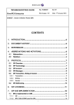
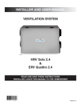
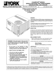
Installation Instructions For Natural Gas Conversion
(Kit Part No. 1173865)
This kit is designed for conversion to Natural Gas.
Natural Gas Orifice Kits and Sizes
Table 1
0 to 2000 ft
Model Number
PGAA, PGMD (All Sizes)
Elevation Above Sea Level
2001 to 4000 ft 4001 to 5000 ft
5001 to 6000 ft 6001 to 7000 ft
7001 to 8000 ft
8001 to 9000 ft
9001 to 10000 ft
Orifice Drill #
44
Kit Number
1173863
Orifice Drill #
(Field-Supplied)
45
Orifice Drill #
(Field-Supplied)
46
Orifice Drill #
(Field-Supplied)
47
Orifice Drill #
(Field-Supplied)
47
Orifice Drill #
(Field-Supplied)
48
Orifice Drill #
(Field-Supplied)
48
Orifice Drill #
(Field-Supplied)
49
PGAD, PGME (All Sizes)
44
1173863
45
46
47
47
48
48
49
PGX3, PDX3 (All Sizes)
44
1173863
45
46
47
47
48
48
49
PGC***K040F, GPCM**K040
PGC***K060F, GPCM**K060
PGC***K080F, GPCM**K080
PGC***K100F, GPCM**K100
PGC***K120F, GPCM**K120
PGC***K140F, GPCM**K140
44
44
44
41
42
42
1173863
1173863
1173863
1173865
1173865
1173865
45
45
45
43
43
43
46
46
46
43
43
43
47
47
47
43
44
44
47
47
47
44
44
44
48
48
48
44
45
45
48
48
48
45
46
46
49
49
49
46
47
47
PGF***K040F, GPFM**K040
PGF***K060F, GPFM**K060
PGF***K080F, GPFM**K080
PGF***K100F, GPFM**K100
PGF***K120F, GPFM**K120
PGF***K140F, GPFM**K140
44
44
44
41
42
42
1173863
1173863
1173863
1173865
1173865
1173865
45
45
45
43
43
43
46
46
46
43
43
43
47
47
47
43
44
44
47
47
47
44
44
44
48
48
48
44
45
45
48
48
48
45
46
46
49
49
49
46
47
47
PGS***K040F, GPSM**K040
44
1173863
45
46
47
47
48
48
49
PGS***K060F, GPSM**K060
44
1173863
45
46
47
47
48
48
49
PGS***K080F, GPSM**K080
44
1173863
45
46
47
47
48
48
49
PGS***K100F, GPSM**K100
41
1173865
43
43
43
44
44
45
46
PGS***K120F, GPSM**K120
42
1173865
43
43
44
44
45
46
47
PGS***K140F, GPSM**K140
42
1173865
43
43
44
44
45
46
47
PGF3**040
44
1173863
45
46
47
47
48
48
49
PGF3**060
44
1173863
45
46
47
47
48
48
49
PGF3**080
44
1173863
45
46
47
47
48
48
49
PGF3**100
41
1173865
43
43
43
44
44
45
46
PGF3**120
42
1173865
43
43
44
44
45
46
47
PGF3**140
42
1173865
43
43
44
44
45
46
47
Note: "**" or "***" may be any combination of numbers and/or letters in the model number.
Note: The orifice sizes in the chart above derate the input rate at 4% per 1000 feet above sea level for altitudes exceeding 2000 feet above sea level.
Natural gas data is based on .60 specific gravity, a heating value of 1030 Btu/cubic foot, and 3.5 "W.C. manifold pressure.
For fuels with different specific gravity and/or different heating values, consult the National Fuel Gas Code ANSI Z223.1 - 2002/NFPA 54-2002 or
National Standard of Canada, Natural Gas and Propane Installation Code CSA B149.1-00.
Note: If converting from LP gas to Natural gas at altitudes exceeding 2000 feet above sea level, conversion kit (Part #330732-401) is required for proper conversion. For all models, except PGX3, PDX3, and PGF3, a .018 pilot
orifice (Part # 5032110) is also required.
Parts List, Kit # 1173865
Description
Part #
Burner Orifice #41
1096942
Burner Orifice #42
1011351
Pilot Orifice (0.018)
503211
Honeywell Conv. Kit #396222
1172952
Label, Natural Gas Conversion
1173866
Label, Field Conversion
1009678
Instructions
462 06 1211 00
Qty
7
7
1
1
1
1
1
SAFETY REQUIREMENTS
Recognize safety information. This is the safety--alert symbol ! .
When you see this symbol in instruction manuals be alert to the
potential for personal injury.
Understand the signal words DANGER,WARNING, or CAUTION.
These words are used with the safety--alert symbol. DANGER
identifies the most serious hazards, those that will result in severe
personal injury or death. WARNING signifies a hazard that could
result in personal injury or death. CAUTION is used to identify
unsafe practices that may result in minor personal injury or product
and property damage. NOTE is used to highlight suggestions that
will result in enhanced installation, reliability, or operation.
-- 1 --
Installing and servicing heating equipment can be hazardous due
to gas and electrical components. Only trained and qualified
personnel should install, repair, or service heating equipment.
Untrained service personnel can perform basic maintenance
functions such as cleaning and replacing air filters. All other
operations must be performed by trained service personnel. When
working on heating equipment, observe precautions in the
literature, on tags, and on labels attached to or shipped with the
appliance and other safety precautions that may apply.
Follow all safety codes. In the United States, follow all safety codes
including the National Fuel Gas Code (NFGC) ANSI
Z223.1--2006/NFPA 54--2006. In Canada, refer to the of the
National Standard of Canada Natural Gas and Propane
Installation Code (NSCNGPIC) CSA B149.1--05. Wear safety
glasses and work gloves. Have fire extinguisher available during
start--up and adjustment procedures and service calls.
These instructions cover minimum requirements and conform to
existing national standards and safety codes. In some instances,
these instructions exceed certain local codes and ordinances,
especially those that may not have kept up with changing
residential construction practices. We require these instructions
as a minimum for a safe installation.
462 06 1211 00
3/17/06
Important Information
This kit includes a Honeywell conversion kit for converting
Honeywell VR8200, VR8205S, SV9500, SV9501 or VR8204M
gas valves certified for use with Propane Gas (and so marked) to
units functionally the same as the certified furnace for use with
Natural Gas. If converting from propane gas to natural gas, the
gas valve conversion kit, main burner orifices, and pilot orifice, all
found in this kit, must be installed.
For converting the furnace from standard altitude on natural gas to
high altitude (2001 feet above sea level or greater) on natural gas,
the Honeywell conversion kit and pilot orifice changes are not
needed. Only the main burner orifices require changing. Refer to
Table 1 for proper orifice size for specific model number, input
capacity, and installation altitude.
The orifices provided in this kit are stamped to indicate the size
(twist drill number) and are sized for natural gas ONLY. Do NOT
use them with butane or a mixture of butane and propane. The
parts list specifies the size orifices supplied in the kit. Compare the
size marking on the orifices with the sizes as listed in the parts list.
Make sure you have the correct main burner orifices.
Extreme care is used to assure that this kit contains the proper
orifices.
Oversized orifices could result in hazardous
conditions, especially if the venting is inadequate. For that
reason, we recommend that the installer check the size of the
orifice with a new twist drill of the correct size. This procedure
assures that the orifices provided are the correct size.
!
ELECTRIC SHOCK HAZARD/FIRE AND/OR
EXPLOSION HAZARD.
Failure to follow this warning could result in
equipment damage, personal injury, death
and/or property damage.
The gas supply shall be shut OFF prior to
disconnecting the electrical power, before
proceeding with the conversion.
Turn OFF electric power supply at disconnect
switch or service panel before starting
installation.
Shut off gas supply to furnace at manual shut--off valve before starting installation.
D
Fill out and attach the Field Conversion Label to the front exterior of the furnace.
D
!
EXPLOSION HAZARD
Failure to follow this warning could result in
personal injury, death and/or property damage.
If unit is still running, allow 2.5 minutes after gas
shut off before turning off power, Shut Off electric
power at unit disconnect and service panel.
D
Disconnect electric power supply to the furnace before
starting installation.
D
Check for gas leaks after installation of kit and before attempting to start furnace.
D
Locate the Natural Gas Conversion Label next to the furnace rating plate.
-- 2 --
!
FIRE, EXPLOSION,
POISONING HAZARD.
CARBON
MONOXIDE
Failure to follow these instructions exactly could
result in personal injury, death and/or property
damage.
This conversion kit shall be installed by a
qualified service agency in accordance with the
manufacturer’s instructions and all applicable
codes and requirements of the authority having
jurisdiction. If the information in these
instructions is not followed exactly, a fire, an
explosion or production of carbon monoxide may
result causing property damage, personal injury
or loss of life. The qualified service agency is
responsible for the proper installation of this kit.
The installation is not proper and complete until
the operation of the converted appliance is
checked as specified in the manufacturer’s
instructions supplied with the kit.
Gas Pressure
D
Refer to the furnace rating plate for the approved gas input
rating.
D
Gas input to burners MUST NOT exceed the rated input
shown on rating plate.
D
Do NOT allow minimum gas supply pressure to vary downward. Doing so will decrease input to furnace. Refer to
Table 2 for gas supply and manifold pressures.
Table 2
Gas Pressures
Gas
Supply Pressure
Manifold
Type
Recommended
Max.
Min.
Pressure
Natural
7″
13″
4.5″
3.5″
Installation
!
ELECTRIC SHOCK HAZARD/FIRE AND/OR
EXPLOSION HAZARD.
Failure to follow this warning could result in
property damage, equipment damage, personal
injury and/or death.
Turn OFF gas supply at manual gas valve
before turning OFF electric power supply and
starting installation.
Turn OFF electric power supply at disconnect
switch or service panel before starting
installation.
462 06 1211 00
3/17/06
Disassembly
Figure 2
Refer to Figure 1 and the following steps.
Figure 1
Installing NOx Baffles
Disassembly
or
Changing Main Burner Orifices
1.
1.
After shutting off gas supply and electric power to the unit
remove the access door, exposing gas valve and burner
compartment.
2.
Disconnect gas line from gas valve so manifold assembly
can be removed.
Disconnect wiring at gas valve. Be sure to note the proper
location of any and all electrical wiring disconnected.
If converting from Propane Gas to Natural Gas, remove the
pilot supply line from the gas valve.
3.
4.
5.
Remove the four (4) screws holding the manifold and gas
valve to the manifold supports. Do Not discard any screws.
6.
7.
Carefully remove the manifold assembly.
If converting from Propane Gas to Natural Gas in the state of
California, NOx baffles must be installed to comply with
California law. NOx baffles can be ordered from Fast Parts.
Remove the two (2) screws holding the burner assembly in
place. Install the correct NOx baffle for the unit, if required,
and replace the Burner Assembly using the original two
screws, Figure 2.
-- 3 --
Remove the gas burner orifices from the manifold assembly
using a box end wrench or socket wrench, figure 3, and replace them with the proper orifice size for the specific furnace model, input size, and altutude from table 1.
Figure 3
2.
Changing Orifices
Tighten the orifices so they are 13/16″ from the face of the
orifice to the backside of the manifold (See Figure 4). Make
sure orifice is installed straight so that it forms a right angle
(90°) to the manifold.
462 06 1211 00
3/17/06
Figure 4
Figure 6
Manifold/Orifice Measurement
Burner Pilot Assembly
Measure 13/16″ from face of orifice
to back edge of manifold pipe.
Changing Pilot Burner Orifice
(Required for Converting from Propane Gas
to Natural Gas) (All models except PGF3,
PGX3, and PDX3).
1.
Disconnect the pilot supply line from the pilot burner.
2.
Remove pilot orifice from pilot burner. Replace with natural
gas orifice stamped which is provided in kits (Figure 5)
3.. Reconnect the pilot tubing securely to the pilot burner.
Verify proper relationship of pilot burner assembly per figure 6, prior to completing the conversion.
Changing Pilot Orifice
1.
2.
3.
Remove the regulator cap screw and pressure regulator adjusting screw. (See Figure 10)
Remove the existing regulator spring from the regulator
housing.
Insert the replacement spring (stainless steel) contained in
this kit into regulator housing.
Figure 7
Pilot
Orifice
Typical Gas Valve Honeywell
SV9500
WA
RN
Ho
INLET
Ex
Seplos
ca riou ion
n s
Re res injoHaza
op ad inult. ry o rd.
era s
rd
ea
Ne tingtruc
th
tio
op ver valv
ns
e u
dis rate se to e. befo
re
qu asse valv ols
a m e to
if th lified ble . D
o
fun e ap servvalve not
ctio plia ice . c
n p nce tec all a
rop do hn
erl es icia
y. no n
t
ING
Pilot Adjustment
Outlet Pressure Tap
Connect manometer here to
check outlet pressure. Must be
adjusted per Table 1.
-- 4 --
Wiring
Terminals
R
TE
NI
IG
ll
we
ney
O
F
N
Inlet Pressure
Tap (Hidden)
F
Figure 5
Conversion of Honeywell VR8200, SV9500, SV9501 and
VR8204M Gas Valves using Natural Gas Conversion Kit #
396222.
O
4.
Gas Valve Conversion (Required for Converting
from Propane Gas to Natural Gas)
L
Pilot
Outlet
RO
NT
CO
OUTLET
25-50-06
462 06 1211 00
3/17/06
Typical Gas Valve Honeywell
SV9501
Figure 8
Wiring Terminals
Inlet Pressure
Tap (Hidden)
4.
Install the pressure regulator adjusting screw. This will set
the manifold pressure close to required setting for normal
operation.
5.
6.
Replace the regulator cap screw.
Attach gas valve conversion label (found in Honeywell conversion kit) to gas valve.
Reassembly
INLET
Pilot
Outlet
Pilot
Adjustment
OUTLET
Outlet Pressure Tap
Connect manometer here to
check outlet pressure. Must be
adjusted per Table 1.
Regulator Adjustment
Under Cap
V
INLET
25--22--25
T
Testing for leaks -- After reassembly, turn the gas on and
check all joints for gas leaks using a soapy solution. All
leaks must be repaired immediately.
1.
3.
5.
25--24--98a
Typical Honeywell
Regulator Assembly
Cap Screw
LP
Gas
Black
6.
Natural
Gas
Silver
Pressure
Regulator
Adjusting
Screw
White
White
Spring
Red
Stainless
Steel
7.
-- 5 --
Remove the plug from the Inlet Pressure Tap on gas valve
and install a manometer. (See Figures 7, 8, 9, & 10)
Open manual gas line valve to unit. Check for gas leaks and
correct as necessary. Check supply pressure. Refer to
Table 2 for proper supply pressure values. If not within
these limitations DO NOT OPERATE UNIT, contact gas
supplier.
Close manual gas line valve to unit, remove manometer and
replace inlet pressure tap plug.
Gas Valve Adjustment
OUTLET
ON
OFF
PRESSURE
REGULATOR
HOUSING
D
4.
Inlet
Pressure
Tap 1/8 NPT
Figure 10
Manifold Assembly -- Be sure to engage the main burner
orifices in the proper openings in the burners.
2.
Outlet
Pressure
Tap
1/ NPT
8
HONEYWELL
D
Start--up and Check--out
Typical Gas Valve Honeywell
VR8205S
Figure 9
Reassemble all parts in reverse order as removed. Attach Natural
Gas Conversion Label next to the unit rating plate. Fill out and
attach the Field conversion Label to the front exterior of the
furnace.
8.
With the gas valve knob in the OFF position, remove the
pressure tap plug from the outlet end of the valve, and connect a “U” tube manometer to the pressure port. (See Figure 7, 8, 9 & 10).
Turn the gas valve knob to the ON position and restore electrical power to unit. Cycle the main burner on and off several
times to stabilize the pressure regulator diaphragm. This
MUST be done before an accurate pressure reading can be
obtained.
With the main burner on, read the pressure gauge. Manifold
pressure should be adjusted to values from Table 2. Turn
pressure regulator adjusting screw clockwise to increase or
counterclockwise to decrease manifold pressure. Burner
Input must not exceed nameplate rating. Refer to Section
“Checking Input Rate”.
Turn gas valve to OFF. Remove the pressure gauge and replace the pressure tap plug and pressure regulator cap
screw.
With gas valve on, observe furnace through two or more
complete cycles to be sure all controls are operating.
462 06 1211 00
3/17/06
4.
!
FIRE AND/OR EXPLOSION HAZARD
5.
Failure to follow this warning could result in personal
injury, death, and/or property damage.
6.
Do NOT attempt to light the burner with a match or
flame of any kind.
HEATING INPUT RATE CHECK
The gas input to the unit is determined by measuring
the gas flow at the meter. Measuring gas flow at the
meter is recommended for natural gas units. To
measure the heating input, perform the following
steps:
1. Turn off all other gas appliances that use the same
meter.
2. Turn off gas supply to unit and attach manifold
pressure gauge as instructed in the ”Gas Valve
Adjustment” section.
3. With gas ON to the unit and the unit operating, record
the number of seconds for the gas meter dial to make
one revolution.
Table 3
Divide number of seconds in Step 3 into 3600
(number of seconds in 1 hour).
Multiply result of Step 4 by the number of cubic feet
shown for one revolution of the meter dial to obtain the
cubic feet of gas flow per hour.
Multiply result of Step 5 by Btu heating value of gas to
obtain total measured input in Btu/hr. Compare this
input rate with the Required Input Rate for the
installation altitude, as shown in Table 3. Consult with
local gas supplier if the heating value of gas is not
known.
Example: Assume that the size of the meter dial is 1 cu. ft.,
one revolution takes 44 seconds, and the heating value of
the gas is 1020 Btu/ft3. Proceed as follows:
1. 38 sec. To complete 1 revolution
2. 3600/38 = 94.7
3. 94.7 x 1 = 94.7
4. 94.7 x 1020 = 96,632 Btu/hr
For this example, the nameplate input is 100,000 Btu/hr, so
only a minor change in manifold pressure is required. In no
case should the final manifold pressure vary more than
+-- .3 ”water column from the values in Table 2. Never
exceed the required input rate (Table 3).
Required Input Rate for All Models
Required Input Rate of Furnace Converted to Natural Gas (Btu/hr)
Elevation Above Sea Level (feet)
Heating Model
0-2000
2001-3000 3001-4000 4001-5000 5001-6000 6001-7000 7001-8000 8001-9000 9001-10000
Size1
"040" or "B"
40,000
35200
33600
32000
30400
28800
27200
25600
24000
"060" or "C"
60,000
52800
50400
48000
45600
43200
40800
38400
36000
"080" or "D"
80,000
70400
67200
64000
60800
57600
54400
51200
48000
"100" or "E"
100,000
88000
84000
80000
76000
72000
68000
64000
60000
"120" or "F"
120,000
105600
100800
96000
91200
86400
81600
76800
72000
"140" or "G"
140,000
123200
117600
112000
106400
100800
95200
89600
84000
1
Note:
For PGF3, PGX3, and PDX3 models, heating model size is indicated by the numbers in the 5th, 6th, and 7th characters in the model number.
For PGF, PGC, PGS models, heating model size is indicated by the numbers in the 8th, 9th, and 10th characters in the model number.
For GPFM, GPCM, and GPSM models, heating model size is indicated by the numbers in the 8th, 9th, and 10th characters in the model number.
For PGAA, PGAD, PGCA, and PGCD models, heating model size is indicated by the letter in the 7th character in the model number.
For PGMD and PGME models, heating model size is indicated by the letter in the 7th character in the model number.
-- 6 --
462 06 1211 00
3/17/06
Pilot Burner Flame Check (All models
except PGF3, PGX3, and PDX3)
Adjust flames so they surround 3/8″ (9 mm) to 1/2″ (13 mm) of the
sensor tip (See Figure 11).
1.
2.
3.
Remove the cap from the pilot adjusting screw (See Figures 7 & 8).
Turn pilot adjusting screw counterclockwise to increase,
clockwise to decrease.
D
Stable and blue flames (See Figure 12). Dust may cause
orange tips or wisps of yellow, but flames MUST NOT have
solid, yellow tips.
D
Flames extending directly from burner into heat exchanger.
D
Flames DO NOT touch sides of heat exchanger
Main Burner
BLUE FLAME
Pilot Burner (HSP)
Proper Flame
Adjustment
Check for the following:
Figure 12
Replace the cap on the pilot adjusting screw.
Figure 11
Main Burner Flame Check
Sensor Tip
Hot Surface
Igniter
25--00--07a
10--11--65
-- 7 --
462 06 1211 00
3/17/06