1
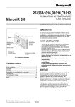
HONEYWELL
R7426A,B,C
MicroniK 200
TEMPERATURE CONTROLLER
WITH AND WITHOUT REAL-TIME CLOCK
INSTALLATION & START-UP INSTRUCTIONS
GENERAL
This document provides instructions and procedures for
installing and starting up the Micronik 200 R7426A,B,C
controllers. No special tools are required for mounting and
installation. The user interface and liquid-crystal display allow
accurate and easy parameter setting and output adjustment.
BEFORE INSTALLATION NOTE
•
•
•
Fig. 1. Temperature Controller
•
Contents
General................................................................................ 1
Before Installation Note ....................................................... 1
Mounting.............................................................................. 1
Wiring .................................................................................. 2
Power Supply and Grounding.............................................. 2
Configuration and Control Parameters ................................ 3
Configuration Settings ......................................................... 6
Parameter Settings and Adjustment .................................... 8
Operating Overview............................................................11
Notes (with RTC, only)....................................................... 19
Copyright © 2007 Honeywell GmbH All Rights Reserved
•
•
•
Visually inspect equipment for shipping damage.
Report any damage to the appropriate Honeywell
representative.
Refer to job drawings for specific installation
information and mounting location.
Verify the controllers will be adequately separated
from the main power supply, relays, or other equipment which can possibly generate electromagnetic
interference.
Verify that the ambient temperature and the humidity
at the controllers will not exceed 0...50°C (32...122°F)
and 5 to 95% rh.
Use shielded wiring in areas with high EMI.
All wiring should be separated from power lines by at
least 150 mm (6’’).
Do not install controllers near frequency converters
or other high-frequency sources.
MOUNTING
The controllers can be mounted in an electric cabinet or other
suitable enclosure. They are suitable for back panel, DIN rail,
wall, or front panel mounting. The corresponding mounting
sequence, as well as dimensions and panel cut-out, are
illustrated in the mounting instruction sheet EN1B-0202GE51
supplied with the controllers.
If the compensation sensor signal (T3) is received from
another controller (parallel connection of compensation
sensor inputs), the jumper W303 has to be cut before
mounting the controller (see Fig. 2). This disconnects the
sensor from the internal power supply.
EN1B-0203GE51 R0507C
R7426A,B,C TEMPERATURE CONTROLLER WITH AND WITHOUT REAL-TIME CLOCK
WIRING
Screwless type, spring loaded terminals are provided on
the controllers for panel and field wiring. These terminals
are suitable for solid conductors as well as tinned or with
multicore cable end, stranded wires up to 1.5 mm2. To
make a termination, push the wire into the terminal or insert
a small screwdriver from the front of the controller into the
spring-release hole and insert the wire. Check for proper
connection by short pull on the wire.
W303
Table 1. Terminal Connection
controller to CPA/SPA potentiometer
R7426A,B,C
T7412B1016
terminal 2
terminal 4
terminal 4
terminal 5
R7426A,B,C 43193982-001
terminal 2
terminal 4
terminal 1
terminal 3
Fig. 2. Parallel Connection of Compensation Sensor T3
T7412B1057/1008 T7412B1024
T7412C1030/1006 T7412B1040
terminal 4
terminal 6
Table 3. Jumper States
state
description
closed
T3 supplied by this controller
W303
T3 supplied from another
open
controller
1)
Default jumper position = closed. Cut (open) jumper W303
only if the T3 input is fed from another controller (parallel
connection, max. six devices). This disconnects the T3 input
from the internal power supply
terminal 4
jumper1)
terminal 5+6
-
-
-
-
Table 2. Wire Dimensions
length max.
type of
wiring run
wires
1.0 mm2
1.5 mm2
from controller to all
local
input and output
100 m
150 m
standard
devices
Wiring should be done only according to the actual job
wiring diagrams or wiring diagrams shown in the mounting
instruction sheet EN1B-0202GE51. The wiring to the
CPA/SPA potentiometers is described in Table 1. All wiring
must conform to applicable codes, ordinances, and
regulations. The maximum allowed wiring length per wire
size are shown in Table 2.
POWER SUPPLY AND GROUNDING
3. Connect transformers 24 Vac secondary to the controller
terminals 18 and 19. Connect one conductor to terminal
marked 24 V∼ and the other to terminal marked 24 V⊥. If
controllers are interconnected all terminals 19 must be
connected to the same potential 24 V⊥ level.
4. Do not connect the secondary side of the transformer to
the installation ground.
1. Refer to job drawings and verify correct supply voltage to
transformer (230 Vac) and controller (24 Vac).
2. Connect line power conductors to transformer primary.
Line power must be supplied from a breaker panel with
dedicated controller circuit. Do not turn the line power on
until all wiring has been checked against job drawings.
EN1B-0203GE51 R0507C
2
R7426A,B,C TEMPERATURE CONTROLLER WITH AND WITHOUT REAL-TIME CLOCK
CONFIGURATION AND CONTROL PARAMETERS
The controllers R7426A,B,C include two groups of settings*) (I and II) for control and configuration parameters that are
automatically selected during programming. For parameter Ctrltyp = Lo, setting I is selected, and for parameter Ctrltyp =
Hi1/Hi2, setting II is selected.
config. par.
no.
name
default
setting
description
C.01 DIR/REVY1 Selects the output action of Y1 to adapt the valve or damper direction
C.02 DIR/REVY3 Selects the output action of Y3 to adapt the valve or damper direction
C.03 DIR/REVY2 Selects the output action of Y2 to adapt the valve or damper direction
Dir Direct acting output signal
Rev Reverse acting output signal
C.04 Ctrltyp1)
Control type selects the setpoint operating range and default parameter
setting I or II.
setpt.
C.05 CPATYP
operating range
CPA potentioCPA/SPA
TYP meter range range
0
1
C.06 YRange
C.07 Startup
C.08 Y1Mode
C.09 Y3Mode
C.10 Y2Mode
C.11 YMode
Dir
Dir
Dir
setting
Lo 0...50°C
for ventilation systems (factory preset)
Hi1 0...130°C
for heating systems
Hi2 0...130°C
with pump ON/OFF operation
Selects the Control Point /SetPoint Adjustment type.
R7426
A B C
*)
actual
value
x
x
x
Lo
for I
x
x
x
0
x
x
x
I
II
II
sensor / remote setpoint unit type
numbers
internal
CPA: ±5K
953...1053Ω CPA: ±5K
internal
T7412B1016 (Pt 1000)
T7412B1057 / T7412C1030 (Pt 1000)
2
100kΩ...0Ω CPA: ±5K
T7412B1008 / T7412C1006 (NTC 20kΩ)
43193982-001
SPA:
T7412B1024 (BALCO 500)
3
10...20kΩ
15 ... 30°C
T7412B1040 (Pt 1000)
4
0...10kΩ
CPA: ±5K
HCW 23 (setpt wheel printed with +/- 5 K)
5
0...100kΩ
SPA: 15...30°C 43193982-001
SPA: 0...50°C 43193982-001
6
0...100kΩ
or 0...130°C
Selects the output control range for all outputs (Y1, Y2, and Y3)
0
2 ... 10 Vdc
1
0 ... 10 Vdc
Enables the start-up routine
OFF Disabled
ON Enabled
Y1 output mode selects an individual output function for Y1
Y3 output mode selects an individual output function for Y3
Y2 output mode selects an individual output function for Y2
0
Synchronous / floating
1
2 stage ON/OFF
2
3 stage binary coded ON/OFF
3
Pulse-width modulation
4
Unconfigured
Selects the output mode for sequence operation or multistage ON/OFF func.
0
Damper, cooling and heating (Y1,Y2, Y3)
Sequence
control for heating or cooling (Y1,Y2, Y3);
1
or 6-stage ON/OFF
Sequence control for heating (Y1, Y3) and cooling (Y2);
2
or 4-stage ON/OFF for heating (Y1, Y3), and cooling (Y2)
Sequence control for cooling (Y1, Y3) and heating (Y2);
3
or 4-stage ON/OFF for cooling (Y1, Y3), and heating (Y2)
4
Two-position damper control (Y1), heating (Y3) and cooling (Y2)
5
15-stage binary coded ON/OFF for heating (Y1, Y3), and cooling (Y2)
Table 4. Configuration parameters R7426A,B,C
3
1
x
OFF
4
4
4
x
x
x
x
x
x
0
x
x
x
x
x
x
x
x
x
x
x
x
x
x
EN1B-0203GE51 R0507C
R7426A,B,C TEMPERATURE CONTROLLER WITH AND WITHOUT REAL-TIME CLOCK
config. par.
no.
description
name
default
setting
I / II
R7426
A B C
0
x
x
x
0/1
x
x
x
0
x
x
x
0/1
x
x
x
3
x
x
x
x
x
x
C.18 PSTG_H2) 3) Determines the prestart gradient to reach the comfort setpoint for heating.
Min. 0 (disabled)
Max. 2
0 K/min x
x
x
C.19 PSTG_C2) 3) Determines the prestart gradient to reach the comfort setpoint for cooling.
Min. 0 (disabled)
Max. 2
0 K/min x
x
x
C.20 tvd2)
Determines the damper prestart time before scheduled comfort mode
Min. 0 (normal control)
Max. 90
15 min
x
x
C.21 Adapt2)
Optimum Start Self Adaption speed
Min. 0
Max. 100
50%
x
x
x
C.22 Adr1)
Sets the serial communication address, used for service or maintenance.
Min. 0
Max. 255
254
x
x
x
0
x
x
x
C.12 T2ext
Enable / Disables the T1 sensor input to be used for both T1 and T2 inputs.
0
T2 installed
1
T1 signal used for T2
C.13 LimTyp
Limitation type determines whether the limit function is low or high.
0
Low limit
1
High limit
C.14 Senstyp
Sensor type determines automatic detection or manual selection of NTC
sensors.
0
Auto detection
1
NTC sensor type
C.15 Y1CTRF
Controls the action of Y1 or activates the occupancy input for summer/winter
changeover.
R7426A
0
cooling
1
heating
2
summer/winter changeover
R7426B,C
0
mixed air damper
1
energy recovery
C.16 AddHour2) Adjusts the month for winter/summer time change.
Min. 0 (disables winter/summer time change)
Max. 12
C.17 SubHour2) Adjusts the month for summer/winter time change.
Min. 0 (disables summer/winter time change)
Max. 12
C.23 DefProg
1)
2)
3)
Initiates the default programming.
0
No Default programming
1
Initiates Default programming
actual value will not be changed during reset to default parameter
on Controllers with Real-Time Clock, only
can be overwritten by controller for self-adaption purposes, resolution = 0.01 K/min
For detailed information of configuration parameters see chapter Configuration Settings.
Table 4. Configuration parameters R7426A,B,C (part 2)
EN1B-0203GE51 R0507C
4
(March)
10
(Oct.)
actual
value
R7426A,B,C TEMPERATURE CONTROLLER WITH AND WITHOUT REAL-TIME CLOCK
control par.
setting I / setting II
description
no. name
low
high
def.
resolution
unit
R7426
A B C
P.01 W1
Main setpoint for input T1
0
50 /
130
21 /
70
0.5
°C
x
x
x
P.02 Wlim
Limit setpoint (low or high) for input T2
5/
30
50 /
130
16 /
90
1
°C
x
x
x
P.03 Wcomp
Compensation changeover point for input T3
-5
40
20
1
°C
x
x
x
P.04 Wi
Winter compensation authority
-350
+350
0
2
%
x
x
x
P.05 Su
Summer compensation authority
-100
+100
0
1
%
x
x
x
P.06 Wcas
Submaster or cascade setpoint
OFF, 0
50
20
0.5
°C
x
x
x
P.07 Rcas
Cascade reset span adjustment
0
40
10
0.5
K
x
x
x
P.08 Xp1
Throttling range (main control loop) for T1
0.5
40
2
0.5
K
x
x
x
P.09 Xp2
Throttling range (cascade or limit control loop)
for T2
0.5
40
10
0.5
K
x
x
x
P.10 Xpc
Cooling throttling range for sequence control
OFF, 1
40
3
0.5
K
x
x
P.11 Xph
Heating throttling range for sequence control
1
40
6
0.5
K
x
x
P.12 tr11)
Reset time (main control loop)
OFF,
20 sec
20
min
OFF
10/
0.5
sec/
min
x
x
x
P.13 tr21)
Reset time (cascade control loop)
OFF,
20 sec
20
min
OFF
10/
0.5
sec/
min
x
x
x
P.14 MINPOS
Minimal pos. for air damper actuators
0
50
20
1
%
x
x
P.15 Ystart
Start point for mid range shift of output Y1
-20
+20
0
0.5
K
x
x
x
P.16 SOFFS
Offset of main setpoint in Standby mode
0
10
2
0.1
K
x
x
x
P.17 T1Cal
Calibration of temperature sensor T1
-20
+20
0
0.1
K
x
x
x
P.18 T2Cal
Calibration of temperature sensor T2
-20
+20
0
0.1
K
x
x
x
P.19 T3Cal
Calibration of temperature sensor T3
-20
+20
0
0.1
K
x
x
x
P.20 RetOffs
Return air offset to simulate exhaust air cond.
OFF, 0
5
OFF
0.1
K
x
x
P.21 RuntimeY1 Actuator run time for Y1
6
180
60
1
sec
P.22 RuntimeY3 Actuator run time for Y3
6
180
60
1
sec
x
P.23 RuntimeY2 Actuator run time for Y2
6
180
60
1
sec
x
P.24 NightLow
P.26 NOFFS
x
2)
Night low limit against temperature extremes
OFF, 8
19
OFF
1
°C
x
x
x
2)
Night high limit against temperature extremes
OFF, 21
40
OFF
1
°C
x
x
x
0
30
5
0.1
K
x
x
x
P.25 NightHigh
2)
x
Offset of main setpoint in Night mode
1)
for tr > 2 min ⇒ resolution = 0.5 min, for tr < 2 min ⇒ resolution = 10 sec
2)
on Controllers with Real-Time Clock, only
actual
value
For detailed information of control parameters see chapter Parameter Settings and Adjustment.
Table 5. Control parameters R7426A,B,C
5
EN1B-0203GE51 R0507C
R7426A,B,C TEMPERATURE CONTROLLER WITH AND WITHOUT REAL-TIME CLOCK
CONFIGURATION SETTINGS
The controllers R7426A,B are supplied with unconfigured
outputs to avoid damage of installed final control devices by
supply of not applicable output signals if the controller power
supply is turned on.
All configuration parameters must be set to select the correct
control functions as required for the job application and to
start control operation and synchronization of the final control
devices.
Table 6. Selection of CPA/SPA Type
CPATYP
CPA / SPA
range
CPA: ±5 K
CPATYP 1
CPA: ±5 K
(953...1053Ω)
CPATYP 0
CPATYP 2
(100kΩ...0Ω)
Direct - Reverse Action
Dir/Revx, x = Y1, Y2 or Y3 (C.01...C.03)
The output action of the analog outputs on the R7426C
controller must sometimes be reversed for a correct opening
and closed direction of the valve or damper. This depends on
whether the output controls a 2-way or 3-way valve or on the
direction the damper shaft moves to open the damper (cw or
ccw). It is needed only if the actuator does not provide a
direction selector switch, plug, or similar.
In the case of the R7426A,B controllers, the direction can be
changed by exchanging the wiring connections open-close
(OUT2-OUT1).
CPATYP 3
(10...20kΩ)
CPATYP 4
(0...10kΩ)
CPATYP 5
(0...100kΩ)
CPATYP 6
(0...100kΩ)
CPA: ±5 K
SPA:
15 ... 30°C
sensor /
remote setpoint unit type
internal
T7412B1016 (Pt 1000)
T7412B1057 (Pt 1000)
T7412C1030 (Pt 1000)
T7412B1008 (NTC 20kΩ)
T7412C1006 (NTC 20kΩ)
43193982-001
T7412B1024 (BALCO 500)
T7412B1040 (Pt 1000)
CPA: ±5 K
HCW 23 (setpoint wheel
printed with +/- 5 K)
SPA:
15...30°C
43193982-001
SPA: 0...50°C
43193982-001
or 0...130°C
Output Control Range Selection
YRange (C.06)
Operating Range Selection Ctrltyp (C.04)
The controllers provide two operating ranges which can be
selected by the configuration parameter Ctrltyp
(Lo = 0...50°C, Hi1/Hi2 = 0...130°C).
Depending on this parameter setting, the setpoint ranges for
the main temperature (W1), limit temperature (Wlim), and
submaster temperature (Wcas) are selected for air temperature applications (Ctrltyp = Lo) or for flow water
temperature applications (Ctrltyp = Hi1/Hi2).
If the configuration parameter Ctrltyp = Hi1, normal operation
for flow water application will be performed. If Ctrltyp = Hi2,
the following additional function will be active on controllers
with real-time clock:
The controller switches the ON/OFF output (e.g. the pump)
from ON to OFF if
- the outside air temperature is above 8°C and
- the output signal Y1 = 0% for more than 5 minutes during
the controller is in the Comfort, Standby, or Night mode.
Changing the configuration parameter Ctrltyp value from Hito Lo control range or vice versa causes the controller to
change all parameter values to default, depending on the
selected Ctrltyp value.
For a direct parameter reset by the user, refer to chapter How
to reset Parameter Values to Default Values? on page 12.
The configuration parameter YRange is available only on the
R7426C controller and is required to select the output control
range (0...100%) to either 2...10 Vdc (YRange = 0) or
0...10 Vdc (YRange = 1). The selected control range is
common to all outputs.
Enabling the Start-up Routine (C.07)
A start-up routine is provided to prevent start-up problems for
the R7426B,C controllers (three outputs). This routine can be
enabled by setting the configuration parameter Startup to
ON.
Individual Output Function Selection
YxMode, x = 1, 2, or 3 (C.08...C.10)
The R7426A,B controllers provide a choice of output signals
suitable for operating a range of final control devices
according to the configuration parameter Y1Mode (for
R7426A,B) and Y2Mode, Y3Mode (for R7426B, only).
Each output can be configured individually by this configuration parameter (see Table 7).
Table 7. Individual Output Function Selection
output function
Control Point / Setpoint Adjustment CPATYP
(C.05)
Valve or damper actuators (floating mode)
2-stage ON/OFF Sequence Control
3-stage Binary ON/OFF Sequence Control
Electric Heat Current Valve (pwm output)
unconfigured
The control point or setpoint can be adjusted via the internal
or external potentiometer connected to the CPA/SPA input.
The potentiometer type is selected by the configuration
parameter CPATYP (see Table 6).
EN1B-0203GE51 R0507C
6
YxMode
(x = 1, 2 or 3)
0
1
2
3
4
R7426A,B,C TEMPERATURE CONTROLLER WITH AND WITHOUT REAL TIME CLOCK
Output Signal Mode YMode (C.11)
Supply of Temperature Signal T2
T2ext (C.12)
Sequence Operation
The controllers R7426B,C are supplied from the factory
configured for sequence operation of heating, mixed air, and
cooling control.
The sequence operation can be configured for the following
control applications by the control parameters YMode and
Y1CTRF (see Table 8). Sequence control will be activated if
at least one control parameter YxMode is not equal 4
(R7426B, only).
Table 8. Sequence Operation Selection
sequence control
YMode Y1CTRF YxMode
for cooling with three outputs
1
0
0
(Y1, Y2, Y3)
for heating with three outputs
1
1
0
(Y1, Y2, Y3)
with two outputs (Y1, Y3) for
heating and one output for
2
n.a.
0
cooling (Y2)
with one output (Y2) for
heating and two outputs for
3
n.a.
0
cooling (Y1, Y3)
damper, cooling and heating
(Y1, Y2 and Y3)
0
0
0
energy recovery, cooling and
heating
0
1
0
If sensor T1 is used also for high or low limit control, the configuration parameter T2ext must be set to 1. This interconnects the T1 and T2 input internally and the sensor has to
be connected only to the T1 input.
By using a limit temperate sensor T2, the parameter T2ext
has to be set to 0 (default).
Limit Type LimTyp (C.13)
The configuration parameter LimTyp allows the selection of
high or low limit control. High limit control is performed if
configuration parameter LimTyp = 1; low limit control is
performed if configuration parameter LimTyp = 0.
Sensor Type Senstyp (C.14)
Three different sensor types can be used with the controller
(see Table 10).
Table 10. Sensor Types
automatic ID
of sensor type
-30....+130°C
1000Ω at 0°C
-30....+130°C
500Ω at 23.3°C
-30....+85°C /
NTC 20kΩ
20kΩ at 25°C
1)
-30....+130°C
1) NTC sensor is detected automatically if, during powerup, the sensor temperature is within -30....+85°C and the
configuration parameter Senstyp = 0. NTC sensor is
selected manually if the configuration parameter Senstyp
is set to 1.
In the case of the three floating output controller R7426B,
several ON/OFF sequence control functions can be selected
by the configuration parameter YMode (see Table 9).
1
4 (x=1, 2,
Y1,Y2,Y3 n.a.
and 3)
Automatic identification of sensor type is selected if the
configuration parameter Senstyp = 0 (default). After power up
reset, the controller detects automatically the type of sensor
connected to the main temperature input T1. For correct auto
detection, it is necessary that the measured temperature be in
the specified range (see Table 10). The same type of sensor
must be used for all temperature inputs (T1, T2 and T3).
2
4 (x=1
and 3)
Y1,Y3
Output Control Function Y1CTRF (C.15)
3
4 (x=1
and 3)
Y1,Y3
5
n.a.
Y1,Y3
4
n.a.
Y1
Table 9. Multistage Selection
6-stage ON/OFF
sequence control
4-stage ON/OFF
sequence control
heating
4-stage ON/OFF
sequence control
cooling
15-stage binary
coded ON/OFF
sequence control
H.
two-position
damper control
1)
characteristics
Pt 1000
BALCO 500
Multistage ON/OFF Function
output function
temperature
range
YMode
YxMode
provided
by
output
function
of Y2
The R7426A controller performs cooling control if the
configuration parameter Y1CTRF is set to 0. A rise in the
measured variable will increase the output value (direct
acting). The control action must be reversed for heating
control by setting the control parameter Y1CTRF to 1. A rise
in the measured variable will decrease the output value.
If the configuration parameter is set to 2, the R7426A
controller provides summer/winter changeover control by a
potential-free contact connected to the occupancy input
(terminals 1 and 4).
In the case of the R7426B,C controller, the configuration
parameter Y1CTRF has to be set to 0 (default) to perform
mixed air damper control and to 1 for energy recovery
systems.
according
to
Y2Mode
Y2 and
Y3 1)
individual (cooling and heating)
In the case of the R7426B,C controller, the output Y1 can be
configured for two-position damper control by setting the
configuration parameter YMode to 4.
7
EN1B-0203GE51 R0507C
R7426A,B,C TEMPERATURE CONTROLLER WITH AND WITHOUT REAL TIME CLOCK
Summer / Winter Time Change
AddHour / SubHour (C.16 / C.17)
Default Programming DefProg (C.23)
Setting the control parameter DefProg to 1 resets all control
and configuration parameters to defaults (see Table 4 and
Table 5). Default programming is indicated by a display of def.
After default programming, the parameter DefProg is reset to
0.
These configuration parameters are only available on
controllers with RTC. The configuration parameter AddHour
or SubHour are required to adjust the month for
summer/winter time change or vice versa.
The actual clock is incremented by one hour at 2:00 on the
last sunday of the month for winter/summer time change
(AddHour). The actual clock is decremented by one hour at
2:00 on the last sunday of the month for summer/ winter time
change (SubHour).
PARAMETER SETTINGS AND
ADJUSTMENT
Main Setpoint W1 (P.01)
The main setpoint is either set by the control parameter W1 or
by the external setpoint potentiometer if the configuration
parameter CPATYP = 3, 5 or 6.
Prestart Gradients PSTG_H / PSTG_C
(C.18 / C.19)
The configuration parameter PSTG_H or PSTG_C are
necessary for the optimum start program on controllers with
RTC. For heating and cooling applications, these parameters
determine the prestart gradient to reach the comfort setpoint
at occupancy start.
If the comfort setpoint will be reached earlier or later than
expected, the controller corrects the prestart gradient by selfadaption routine to optimize the start cycle.
The optimum start cycle for heating or cooling can be
disabled by setting PSTG_H or PSTG_C to 0.
High/Low Limit Setpoint Wlim (P.02)
For high or low limit control, the control parameter Wlim is
used as setpoint.
During limit control, the throttling range Xp2 and reset time
tr2 are active.
Limit control will be active only if the T2 temperature signal
(control parameter T2ext = 0) is available or alternatively the
sensor T1 (control parameter T2ext = 1) is used also for limit
control.
For cascade control, the limit setpoint Wlim determines the
control point at which the submaster setpoint (Wcas) maintains
the limit value and is not shifted anymore by the master
control loop.
High or low limit control is in accordance with the configuration parameter LimTyp (C.13).
Optimum Start Self Adaption Speed
Adapt (C.21: Controller with RTC only)
This parameter is used by the self-adaption routine to
optimize the energy consumption during the start cycle. For
this optimization, a corrected prestart gradient is calculated
once per day. The adaption to the actual prestart gradient for
the next optimum start cycle is determined by the self
adaption speed Adapt (0% = adaption disabled and 100% =
max. adaption speed).
Submaster Setpoint Wcas (P.06)
The R7426A,B,C controllers provide cascade control which
uses two control loops, master and submaster to maintain the
master setpoint CTRP1. Cascade control will be active if
temperature sensor T2 is connected and the control parameter Wcas is set to any value other than OFF.
This adjustment sets the control point of the submaster
control loop, discharge temperature (T2), at zero room
temperature deviation. If the room temperature deviates, the
submaster setpoint Wcas is automatically altered.
Cascade control is disabled if the submaster setpoint Wcas is
set to OFF.
Low limit of CTRP2 is performed if control parameter
LimTyp = 0 and high limit of CTRP2 is performed if control
parameter LimTyp = 1.
Damper Prestart Time tvd
(C.20: Controller with RTC only)
The damper prestart time tvd is active with the optimum start
program only and is used to set the time before occupancy
start (scheduled comfort mode) at which the output signal Y1
(damper) switches to normal operation to supply fresh air to
the space in mixed air applications.
Serial Communication Address Adr (C.22)
The configuration parameter Adr sets the serial
communication address.
The serial communication bus allows the connection of the
PC-based Operator’s Terminal to one or several controllers. It
provides access to all application configuration and control
parameters, time schedules, input and output values of the
connected controllers and easy setting of these via the bus by
mouse click or keyboard.
Reset Span Adjustment Rcas (P.07)
The reset span adjustment Rcas determines the reset effect in
Kelvin. The submaster setpoint Wcas is altered if the temperature (T1) deviates by 50% of the throttling range Xp1.
Throttling Range Xp1 / Xp2 (P.08 / P09)
Proportional band (throttling range Xp) adjustment determines
the temperature change, required at the main sensor (T1) and
EN1B-0203GE51 R0507C
8
R7426A,B,C TEMPERATURE CONTROLLER WITH AND WITHOUT REAL TIME CLOCK
Setting Guidelines for Proportional Band of P and
P+I Control
limit or cascade sensor (T2) to operate the output device from
full open (100%) to full closed (0%) or vice versa.
Xp1 is the throttling range for the main control loop, Xp2 is
used if limitation or cascade control (submaster control loop)
is active (see Table 11).
To estimate the proportional band (throttling range Xp) for
stable control under all different load conditions, the control or
correcting range Xh of the heating or cooling coil must be
known. This is the maximum air temperature increase produced by the heating coil or decrease of a cooling coil if the
control valve is fully open.
The proportional band Xp for discharge air control can be
calculated by using the following rule-of thumb formula:
Table 11. Throttling range and reset time reference
application
R7426A Controller
Main Temp.Control
High or Low Limit
Temperature Control
Cascade Control
Master
Submaster
R7426B,C Controller
Main Temp. Seq. Control
Mixed Air Damper
Energy Recovery
Heating
Cooling
R7426B,C Controller
Temperature Cascade
Sequence Control
Master
Submaster
- Mixed Air Dampers
- Energy Recovery
- Heating
- Cooling
sens. Xp1 Xp2 Xpc Xph tr1 tr2
T1
x
T2
x
x
T1
T2
x
T1
T1
T1
T1
x
x
T1
x
x
x
x
x
Xp =
Xh = ϑRA - ϑOAmin
The often-specified accuracy for room control of ±1 (Xp = 2K)
allows a discharge air alteration of 20 °C.
In P+I control the same proportional band can be used as for
P control. The following rule-of-thumb formulae are used for
P+I control:
x
x
x
x
x
x
x
x
x
•
Discharge air control
•
Room control
Xp =
Xp =
Xh
4...5
Xh
∆tmaxdischarge air
or
8...10
8 ... 10
Reset Time tr1 / tr2 (P.12 / P13)
Xw
The control parameters Xpc and Xph are only available on
R7426B,C controllers and are used to set the cooling and
heating throttling ranges for the following applications
• Temperature sequence control with heating, mixed air
dampers, and cooling (see Fig. 3 and Table 11)
• Temperature cascade control with heating, mixed air
dampers, and cooling (see Table 11)
In applications without cooling, the throttling range Xpc must
be set to OFF 100% fresh air supply at actual temperature
above the control point is required (outdoor and return air
dampers fully open).
0
t
Y
P
P %/s
tr
100
P = X Xw %
p
t
tr
Fig. 4. Step change response of P+I control
Y[%]
1/4 Xp1
Xh
∆tmaxdischarge air
or
10
10
The ∆tmax (Xh) of the discharge air for mixed air damper control is the maximum difference between outdoor air (OA)
temperature and return air (RA) temperature.
x
x
x
x
Throttling Range Xpc / Xph (P.10 / P11)
100
Xh
5
For room temperature control, the following rule-of-thumb
formula can be used:
x
x
T2
T2
T2
T2
Xp =
if Xpc = Off
Damper
Y1
Y3
MINPOS
Y2
In the case of combined action including proportional and
integral components (P+I control), the reset time (tr) is
defined as the required time after which the integral part is
equal to the change due to the proportional action for a
predetermined step change in the input variable. See Fig. 4.
The control parameter tr1 sets the reset time of the P+I main
temperature control loop. For limit or submaster cascade
control the control parameter tr2 sets the reset time of these
control loops, e.g. discharge temperature T2 (see Table 11).
If only proportional control is required, parameter tr must be
set to OFF.
Cooling
Heating
if Xpc = Off
0
CTRPH CTRP1
Xph
Xp1
CTRPC
Xwh / Xwc / Xwd
Xpc
T2
Fig. 3. Temperature sequence control with heating, mixed
air dampers, and cooling valve
9
EN1B-0203GE51 R0507C
R7426A,B,C TEMPERATURE CONTROLLER WITH AND WITHOUT REAL TIME CLOCK
Setting Guidelines for Reset Time of P+I Control
Table 12. Calculation of summer/winter compensation
The reset time tr should be adjusted to 2...3 times of the
response time Tu , which is the time interval between the
beginning of a sustained disturbance (e.g. rapid step change
of valve position) and the instant when the resulting change in
the output signal reaches a specified fraction of its final
steady-state value, either before overshoot or in the absence
of overshoot.
The response time Tu in discharge air control is normally in
the range of 0.1 to 0.6 min, which allows adjustments of the
reset time tr in a range of 0.2 to 2 min.
In room control the response time Tu is in the range of
0.5 to 5 min, which results in a setting of 1 to 15 min.
control
schedule
room temp.
(T1)
outdoor air
temp.
(T3/Tcomp)
throttling
range (XP)
20°C
20°C
2°C
22°C
-15°C
2°C
Aut Wi =
Winter
∆T1 + Xp
⋅ 100% =
∆t Outside Air
(22 - 20) + 2
⋅ 100% =≈ 12%
35
20°C
20°C
2°C
26°C
35°C
2°C
∆T1 − Xp
⋅ 100% =
∆t Outside Air
(26 - 20) - 2
⋅ 100% =≈ 27%
15
Aut Su =
Start Point Ystart (P.15)
Summer
This control parameter is available only on the single output
controller R7426A and on the R7426B controller if the three 3position floating outputs are configured for 6-stage ON/OFF
sequence control and on the R7426B,C controllers if YMode
= 1 is selected.
The start point determines the midrange shift of the output Y1
from the calculated control point.
The start point is calibrated in degrees K and is the offset
(plus or minus) from the set values or calculated control
points at which the output Y1 is at 50%. Normally and
especially in P+l control, the start point should be set at zero.
A change is required only in specific applications where a
asymmetrical arrangement results in improved control performance, e.g. if for heat-up of a large space in the morning a
high heat capacity is needed and for normal control the valve
must be opened by only a small amount.
Compensation change-over at +20 °C outdoor air temperature
NOTE: With P+I control Xp = 0
Occupied/Unoccupied Function SOFFS
(P.16)
A potential-free contact can be used between terminals 1 and
4 to switch the controller between occupied (contact closed)
or unoccupied (contact open) mode.
In occupied mode, the temperature set point W1 is used for
the control point calculation. In unoccupied mode, the SOFFS
parameter value is added (cooling) to or subtracted (heating)
from the calculated control point.
In the case of the R7426A controller, the parameter Y1CTRF
must be set to 0 or 1 (≠ Cho) to match the required heating or
cooling application.
If the configuration parameter Y1CTRF is set to 2 (summer /
winter changeover), the parameter SOFFS is not considered.
In sequence applications of heating and cooling, the SOFFS
parameter value is added to the control point for cooling
(CTRPC) and subtracted from the control point for heating
(CTRPH) (see Fig. 5).
Compensation Changeover Point Wcomp
(P.03)
The control parameter Wcomp defines the start point of
summer or winter compensation. Above the compensation
changeover point (Wcomp) summer compensation and below
Wcomp winter compensation is performed.
Summer / Winter Compensation Authority
Su / Wi (P.04 / P.05)
Night Mode Offset NOFFS
(P.26: Controller with RTC only)
These authority settings determine the reset effect (OATComp)
the compensation sensor (T3) has on the main setpoint W1 in
percentages. Outside temperature reset in summer and
winter time are commonly used applications.
To calculate winter and summer authority, the throttling range
must be considered in proportional-only control according to
Table 12.
This control parameter is used to set the night mode offset.
During night mode, freeze protection is active and the
occupied / unoccupied function is inactive.
Night Cycle NightLow and NightHigh
(P.24 and P.25: with RTC, only)
The control parameters NightLow and NightHigh are used
by the night cycle program (controller mode = OFF) to assign
unoccupied night low or high limits for the protection of a
space and its contents against temperature extremes.
EN1B-0203GE51 R0507C
10
R7426A,B,C TEMPERATURE CONTROLLER WITH AND WITHOUT REAL TIME CLOCK
If the controller is in OFF mode, the time schedule program
overrides the minimum position by the ON/OFF input for
plant/system shut off and the damper is driven into the fully
closed position at OFF condition together with the heating and
cooling valve actuators.
Y (%)
100
UNOCCUPIED
Runtimex, x = Y1, Y2, or Y3 (P.21...P.23)
OCCUPIED
SOFFS
SOFFS
Xph
The control parameters Runtimex (x = Y1 for R7426A;
x = Y1, Y2 or Y3 for R7426B) are available only on
R7426A, B controllers.
The controller converts the deviation signal to a proportional
output pulse which drives the actuators depending on the
Runtimex parameter value.
An automatic synchronization function ensures correct
positioning of the actuators. The run time for synchronization
is derived by control parameter Runtimex multiplied by 1.25.
By selection of the output to pwm mode, the pulse-width
modulated output is suitable for driving electric heat current
valves and is controlled from the heating signal. The total
cycle time is set by the control parameter Runtimex.
T (°C)
Xpc
CTRPH CTRPC
Fig. 5. Night cycle NightLow and NightHigh
The night cycle program automatically cycles between the
user selected upper and lower limits and turns on full heating
or cooling with forced return air recirculation or full energy
recovery whenever the limits are reached. The switching
hysteresis is fixed to 1 K.
This function can be disabled for heating and/or cooling by
setting NightLow and/or NightHigh to OFF.
OPERATING OVERVIEW
Display and Operation Elements
The MicroniK 200 user interface is described in Fig. 6.
Calibration of Temperature Sensors
T1CAL, T2CAL, or T3CAL (P.17...P.19)
NOTE: Pushing the + or - button increments/decrements
values or scrolls through the parameter list:
• pushing one time: single step
• pushing without release: automatically inc./dec. or scroll
• after 3 sec pushing without release: fast automatically
increment/decrement or scroll
The controllers include a calibration setting and are factory
calibrated. In case of an offset as a result of long wiring
lengths the temperature sensor inputs (T1, T2, and T3) can
be adjusted separately by the control parameters T1CAL,
T2CAL and T3CAL.
DISPLAY
Return Air Offset RetOffs (P.20)
CONTROLLER MODE
FREEZE PROTECTION
The control parameter RetOffs is available only on R7426B,C
controllers and is used to activate economizer mode (RetOffs
≠ OFF) for mixed air damper (Y1CTRF = 0) or energy
recovery system control (Y1CTRF = 1).
If the main temperature sensor (T1) is installed in the exhaust
air, the control parameter RetOffs should be set to 0. In
applications with the main sensor installed in the room and
with a constant offset between room and exhaust air
conditions, this offset value can be adjusted within 0...5 K by
the control parameter RetOffs. This will be added to the
actual measured room temperature value to simulate exhaust
air conditions.
The economizer mode is disabled if the value of the control
parameter RetOffs is programmed to OFF or if no outdoor air
temperature sensor is connected.
LOW BATTERY*
TIME*
OFF
NIGHT*
STANDBY COMFORT
Date Off
°C % rh min sec K
ENGINEERING UNITS
VALUE
MoTuWeTh Fr SaSu H1 H2 H3
WEEKDAYS / GROUPS*
HOLIDAY SCHEDULE TYPES*
*ON CONTROLLERS WITH REAL-TIME CLOCKS, ONLY.
PUSH BUTTONS
SELECTION OR ESCAPE
ADJUSTMENT OR SELECTION
PARAMETER / VALUE
CONFIRMATION
Minimum Position MINPOS (P.14)
Fig. 6. User interface
The control parameter adjustment MINPOS is available on
R7426B,C controllers only and determines the minimum open
position to which an outdoor air damper actuator can be
driven from the controller. In mixed air damper applications it
maintains the minimum outdoor air damper setting, even
though the temperature input condition calls for a fully closed
position.
11
EN1B-0203GE51 R0507C
R7426A,B,C TEMPERATURE CONTROLLER WITH AND WITHOUT REAL TIME CLOCK
Changing Operating Modes
Fig. 7 shows the six operating modes. After power-up the
controller version is displayed and the controller enters the
standard display mode. In this mode, selected input or output
values and on controllers with real-time clock the time or the
date are displayed. The controller mode is permanently
displayed by a corresponding icon (Fig. 6).
Pushing the SET and SEL button simultaneously for approx.
1 sec causes the controller to leave the standard display
mode and to enter the output data selection mode (Fig. 11).
Pushing the SET button causes the controller to accept the
selected output data no. and to enter the output adjustment
mode (Fig. 12). This mode is used for manual override of
output values. The return to standard display mode is shown
in Fig. 7.
Pushing the + and - button simultaneously for approximately
1 sec causes the controller to leave the standard display
mode and to enter the parameter/configuration selection
mode (Fig. 9). This mode is used for application configuration
and to select parameters for adjustment.
Pushing the SET button causes the controller to accept the
selected parameter or configuration no. and to enter the adjustment mode (Fig. 10), which is used to adjust configuration
/ parameter values. After adjustment, the controller returns to
selection mode by pushing the SET or SEL button. Pushing
the SEL button leads back to standard display mode.
Pushing the SET and - button simultaneously for approx.
1 sec causes the controller to leave the standard display
mode and to enter the clock / schedule selection mode (Fig.
13) on controllers with real-time clock, only.
POWER UP
AUTOMATIC
DISPLAY
AND
AND
FOR APPROX.
1 SEC
FOR APPROX.
1 SEC
OUTPUT
ADJUSTMENT
MODE
OUTPUT
SELECTION
MODE
STANDARD
DISPLAY
MODE
PARAM./CONFIG.
SELECTION
MODE
PARAM./CONFIG.
ADJUSTMENT
MODE
OUTPUT
FIXING
NO PARAMETER
VALUE CHANGE
NO OUTPUT FIXING
AND
RELEASE OF
OUTPUT FIXING
FOR APPROX.
1 SEC
CLOCK /
SCHEDULE
SELECTION
CONTROLLERS WITH
REAL-TIME
CLOCKS, ONLY.
Fig. 7. Operating overview
EN1B-0203GE51 R0507C
12
R7426A,B,C TEMPERATURE CONTROLLER WITH AND WITHOUT REAL-TIME CLOCK
Time Out
After approximately 10 min of inactivity (no button has been
pressed: time out), each mode returns automatically to
standard display mode. Inputs that have not been confirmed
by the SET button are ignored by the controller and old
parameter values will be retained.
A
B
A
°C
TIME &
WEEKDAY
ON CONTROLLERS
WITH REAL-TIME
CLOCK, ONLY
SUBMASTER / LIMIT SETPOINT
CTRP2
We
Date
°C
COMPENSATION
TEMPERATURE T3
DATE
We
°C
% rh
MAIN
TEMPERATURE T1
°C
R7426B,C, ONLY
%
MAIN SETPOINT
CTRP1
°C
HUMIDITY
DEVIATION XWrh
OUTPUT Y1 *)
%
LIMITATION / CASCADE
TEMPERATURE T2
OUTPUT Y2 *)
R7426B,C, ONLY
B
%
OUTPUT Y3 *)
*) THE OUTPUT DATAS (Y1, Y2, AND Y3) ARE
DISPLAYED BETWEEN THE FOLLOWING RANGES:
OUTPUT TYPE
FLOATING
CONTROL RANGE
0...100%
0...10VDC
0...100%
2...10VDC
0...100%
OUTPUT RANGE
0...100%
0...120% --> 0...12V (DIR)
-20...100% --> 12...0V (REV)
-25...125% --> 0...12V
A
*) DURING THE AUTOMATIC SYNCHRONIZATION FOR A CORRECT
POSITIONING OF THE ACTUATORS, Syn IS DISPLAYED TOGETHER
WITH THE CORRESPONDING OUTPUT NUMBER.
Fig. 8. Standard display mode
13
EN1B-0203GE51 R0507C
R7426A,B,C TEMPERATURE CONTROLLER WITH AND WITHOUT REAL-TIME CLOCK
Displaying Actual Values
°C
In the standard display mode, one of nine actual values, the
actual time, or the date can be selected and displayed by
pushing the SEL button.
The icons of the permanently displayed controller mode are
described in the following table:
Table 13. Icons
controller mode / status
display
Off
OFF - icon
Night1)
Moon - icon
Standby
Halfsun - icon
Comfort
Sun - icon
Freeze Protection Alarm and Freeze protection icon in
Operation2)
addition
Low battery 1) 2) 3)
Battery icon
°C
FIRST DISPLAYED CONFIGURATION
PARAMETER:
FOR R7426C
ACTUAL
PARAMETER
VALUE
FOR R7426A,B
Optimum Start 1)
Sun icon is flashing ≈ 1Hz
On controllers with real-time clock, only.
2)
Status information is displayed together with actual icon
for the controller mode.
3)
In order to improve battery lifetime, low battery detection
is performed only once a day and after power up.
If a displayed date is programmed to be a holiday, the
corresponding holiday icon is displayed on controllers with
real-time clock.
1)
NOTE: CONTROL OR CONFIGURATION
PARAMETERS WHICH ARE NOT
AVAILABLE ON THE GIVEN
CONTROLLER VERSION ARE
SKIPPED.
Fig. 9. Parameter/Configuration Selection Mode
Selecting Parameters
OR
The parameter/configuration selection mode is used to select
control and configuration parameters (Fig. 9) for adjustment.
The displayed parameter no. corresponds with the number in
Table 4 and Table 5. Default programming is indicated by a
display of def.
°C
Fig. 10. Parameter/Configuration Adjustment Mode
Pushing the + or - button scrolls through the parameter list.
Pushing the SET button enters the adjustment mode.
Selecting Output Values
The output selection mode is used to select the output no.
(see Fig. 11) for manual override adjustment. An activated
manual override is indicated by a displayed F (fixed).
Adjusting Configuration / Parameter Values
The adjustment mode is used to adjust configuration and
parameter values (Fig. 10). In this mode, the selected parameter no. is displayed and the corresponding value flashes.
Pushing the + or - button scrolls through the output list.
Pushing the SET button enters the adjustment mode.
Pushing the + or - button increments or decrements the value
of the selected parameter. Ranges are shown in Table 4 and
Table 5. An adjustment example is shown in Fig. 18.
Pushing the SEL button retains the old parameter value.
Pushing the SET button accepts the parameter value and
returns to parameter/configuration selection mode.
Manually Overriding Output Values
The output adjustment mode is used for manual override
adjustment of output values (see Fig. 12). In this mode, the
selected output no. is displayed and the actual output value
flashes.
Pushing the + or - button increments or decrements the value
of the selected output for manual override purpose. The
output range is displayed in correspondence with the nominal
control range.
To return to output selection mode, three options are
available:
• Pushing the SET-button after adjustment activates the
manual override (fixing) of output value.
• Pushing the SEL button, causes that the output value is
still determined by the control loop (no fixing).
Resetting Param. Values to Default Values
Pushing simultaneously the + and - button during the power
up or setting the control parameter DefProg to 1 resets all
control and configuration parameters to defaults (see Table 4
and Table 5). Default programming is indicated by a display of
def.
EN1B-0203GE51 R0507C
TO ADJUST
PARAMETER
VALUE
14
R7426A,B,C TEMPERATURE CONTROLLER WITH AND WITHOUT REAL-TIME CLOCK
•
To release the manual override (fixed) of the output, select
the output, enter output adjustment mode and push the +
and - button simultaneously.
Pushing the SEL button leads back to standard display mode.
WITH
:
MANUAL OVERRIDE
IS ACTIVE
%
%
R7426B
AND
R7426C,
ONLY
WITHOUT
:
CONTROL LOOP
IS ACTIVE
%
Fig. 11. Output Selection Mode
%
OR
TO ADJUST
OUTPUT
VALUE
%
%
OUTPUT
SELECTION
%
OUTPUT
VALUE
ADJUSTMENT
OUTPUT
SELECTION
OUTPUT
VALUE
ADJUSTMENT
AND
%
%
MANUAL OVERRIDE
%
NO MANUAL OVERRIDE
%
AUTOMATIC
DISPLAY
FOR APPROX.
1 SEC
OUTPUT
SELECTION
RELEASE OF
MANUAL OVERRIDE
Fig. 12. Output value adjustment for manual override
15
EN1B-0203GE51 R0507C
R7426A,B,C TEMPERATURE CONTROLLER WITH AND WITHOUT REAL-TIME CLOCK
Using the Schedules (with RTC, only)
a normal day (day type = H0 is default). The function is
described as follows:
• H0: no holiday - the weekday schedule applies
• H1: free programmable as for a weekday, but only valid for
the current day.
• H2: as H1 function - free programmable, additional holiday
type, e.g. last or first day after a longer holiday period.
NOTE: After day is passed, day type (H1 or H2) is reset at
24:00 to normal.
• H3: free programmable as for a weekday, but is valid
every year and repeated annually.
The schedule points of the used holiday types (H1, H2 or H3)
must be programmed in the standard schedule. Table 15
shows a programmed example of the holiday schedule (2.7.
till 28.7. = holiday type H1 and 1.5. = holiday type H3).
The H1 and H2 holidays will not be influenced if the user
changes the actual date. If power supply is interrupted for
more than one day, all H1 and H2 holidays within the date of
power supply error and the actual date will be deleted.
Two schedules, one for programming the schedule points and
one for holiday programming, are available.
The standard schedule is used to switch the controller mode
(off, night, standby or comfort) at programmed schedule
points (S1 ... S6), which can be set for each weekday or
weekday group as well as for several holiday types (H1, H2
and H3).
If the comfort or standby mode is taken from the schedule and
if the occupancy switch is connected, the controller mode is
determined by the occupancy input as follows:
• Occupied (contact closed):
Controller mode = Comfort (sun - icon)
• Unoccupied (contact open):
Controller mode = Standby (halfsun - icon)
The OFF and night controller modes are not influenced by the
occupancy input.
Table 14 shows an example of the weekly schedule
programmed with the following default values:
• Mo ... Su from 6:00 till 18:00 = Comfort mode
• Mo ... Su from 18:00 till 6:00 = Night mode
The holiday schedule is used to program each day of the year
(01.01 ... 31.12.) as a holiday (day type = H1, H2 or H3) or as
point 1
point 2
point 3
1)
day
2)
2)
time
SMode
time
SMode
time
point 4
SMode
2)
time
SMode
point 5
2)
time
SMode
point 6
2)
Mo
6:00
comfort
--:-ignore
--:-ignore
--:-ignore
--:-ignore
Tu
6:00
comfort
--:-ignore
--:-ignore
--:-ignore
--:-ignore
We
6:00
comfort
--:-ignore
--:-ignore
--:-ignore
--:-ignore
Th
6:00
comfort
--:-ignore
--:-ignore
--:-ignore
--:-ignore
Fr
6:00
comfort
--:-ignore
--:-ignore
--:-ignore
--:-ignore
Sa
6:00
comfort
--:-ignore
--:-ignore
--:-ignore
--:-ignore
Su
6:00
comfort
--:-ignore
--:-ignore
--:-ignore
--:-ignore
H1
0:00
off
--:-ignore
--:-ignore
--:-ignore
--:-ignore
H2
0:00
off
--:-ignore
--:-ignore
--:-ignore
--:-ignore
H3
0:00
off
--:-ignore
--:-ignore
--:-ignore
--:-ignore
1)
Weekday or holiday type; 2)Programmed controller mode (schedule mode)
Table 14. Example of weekly schedule and holiday types (default)
day
1.
2.
3.
4.
Jan.
H0
H0
H0
H0
Feb.
H0
H0
H0
H0
March
H0
H0
H0
H0
April
H0
H0
H0
H0
May
H3
H0
H0
H0
June
H0
H0
H0
H0
July
H0
H1
H1
H1
August
H0
H0
H0
H0
Sept.
H0
H0
H0
H0
Oct.
H0
H0
H0
H0
SMode
18:00
18:00
18:00
18:00
18:00
18:00
18:00
--:---:---:--
night
night
night
night
night
night
night
ignore
ignore
ignore
Nov.
H0
H0
H0
H0
Dec.
H0
H0
H0
H0
28.
H0
H0
H0
H0
H0
H0
H1
H0
H0
H0
H0
H0
29.
H0
H01)
H0
H0
H0
H0
H0
H0
H0
H0
H0
H0
30.
H0
H0
H0
H0
H0
H0
H0
H0
H0
H0
H0
31.
H0
H0
H0
H0
H0
H0
H0
1)
If the 29th of February is programmed to be a H1 or H2 holiday and the current year is not a leap year, this holiday will be
deleted on March 1.
Table 15. Example of annual schedule (no default)
EN1B-0203GE51 R0507C
16
2)
time
R7426A,B,C TEMPERATURE CONTROLLER WITH AND WITHOUT REAL-TIME CLOCK
Selecting Clock and Schedules (with RTC, only)
DATE & TIME
SELECTION
DATE & TIME
ADJUSTMENT
STANDARD
SCHEDULE
SELECTION
STANDARD
SCHEDULE
PROGRAMMING
HOLIDAY
SCHEDULE
SELECTION
HOLIDAY
SCHEDULE
PROGRAMMING
Programming Standard Schedule (with RTC, only)
The standard schedule programming is used to program up to
6 schedule points for each weekday as well as for three
holiday types. The controller mode (off, night, standby or
comfort) will be switched at these programmed schedule
points.
The first step of the schedule programming (see Fig. 15) is to
select a weekday or holiday type as follows:
1. Mo ... Su as single
2. H1 ... H3 as single
3. Mo ... Fr grouped
4. Sa and Su grouped
5. Mo ... Su grouped
The switching time is adjustable in steps of 10 min. To ignore
a schedule point, the displayed switching time must be set to
‘--:--’ by adjusting it between step 23:50 and 0:00 or by
Fig. 13. Clock and schedules selection mode
The clock and schedule selection mode is provided to select
real-time clock (RTC), standard schedule (SCH), or holiday
schedule (Hol) for programming (see Fig. 13).
pushing the + and - button simultaneously.
Pushing the SEL button returns to the selection mode,
ignoring adjustments which have not been confirmed by the
SET button.
Pushing the + or - button scrolls through the selection list.
Adjusting Date and Time (with RTC, only)
This mode is used to adjust date and time (real-time clock) by
the input sequence shown in Fig. 14.
During date adjustment, the weekday is calculated automatically and need not be programmed. The 29th of February
is adjustable only for leap years.
Pushing the SEL button returns to the selection mode,
ignoring adjustments which have not been confirmed by the
SET button.
Due to battery change or low battery, the date / time can be
invalid and is displayed as --.--. -- / --:-- on the LCD. In this
case the controller behaves like a controller without real-time
clock. If the occupancy input is inactive, the controller will be
assumed as occupied.
TIME ADJUSTMENT
OR
TO ADJUST
MINUTES
OR
TO ADJUST
YEAR
OR
TO ADJUST
MONTH
OR
TO ADJUST
DAY
TO SELECT
WEEKDAY,
WEEK GROUPS,
OR HOLIDAY
TYPES
OR
TO ADJUST
SCHEDULE
POINT
OR
TO ADJUST
HOURS
OR
OR
OR
TO ADJUST
SWITCHING
TIME
TO ADJUST
CONTROLLER
MODE
Tu
Tu
Tu
Fig. 15. Standard schedule programming
DATE ADJUSTMENT
Date
Date
Date
Fig. 14. Date and time adjustment mode
17
EN1B-0203GE51 R0507C
R7426A,B,C TEMPERATURE CONTROLLER WITH AND WITHOUT REAL-TIME CLOCK
Programming Holiday Schedule (with RTC, only)
Interpreting Error Messages
The holiday schedule programming is used to program each
day of the year (01.01 ... 31.12.) as a holiday (day type = H1,
H2 or H3) or as a normal day (day type = H0 is default).
Different analog input errors can be identified by the controller
(Error handling). The defective analog input (T1, T2, T3 or
Xwrh) will be displayed in the standard display mode (see Fig.
17) after the corresponding value is selected.
NOTE: For the external CPA/SPA potentiometer input, no
error message is indicated if the potentiometer or
wiring is defective. In this case, for control point or
setpoint calculation, the following values are used:
• for CPATYP 0, 1 or 2 ⇒ CPA value = 0
• for CPATYP 3 ⇒ SPA value = control parameter W1
Pushing the + or - button during the first step of the holiday
programming (see Fig. 16) toggles between all programmed
holidays (≠ H0) and displays them (type and date).
If none of the 365 days of a year is programmed to be a
holiday, the actual date is displayed, marked as normal day
(H0).
Pushing the SET button selects the displayed holiday and
enters the adjustment for date and day type.
To program a new holiday, select any holiday, adjust date
(and holiday type if necessary) and confirm the changes by
pushing the SET button. To reset a holiday to normal day, day
type H0 has to be set for the specific day.
Pushing the SEL button returns to the selection mode,
ignoring adjustments which have not been confirmed by the
SET button.
OR
TO
TOGGLE/DISPLAY
PROGRAMMED
HOLIDAY
DISPLAY SHOWN IF NO SENSOR
IS CONNECTED DURING POWER-UP
°C % rh
STANDARD
DISPLAY
We
SPACE
DISPLAY SHOWN AFTER ERROR
IDENTIFICATION DURING OPERATION
°C % rh
STANDARD
DISPLAY
AND
: MAIN TEMPERATURE SENSOR T1 IS DEFECTIVE
AND
: LIMITATION OR CASCADE TEMPERATURE SENSOR T2 IS DEFECTIVE
AND
: COMPENSATION TEMPERATURE SENSOR T3 IS DEFECTIVE
AND
: ERROR OF HUMIDITY DEVIATION INPUT XWrh
TEMPERATURE DISPLAY IN °C
HUMIDITY DEVIATION DISPLAY IN % rh
OR
TO ADJUST
MONTH
Fig. 17. Error handling
Sa
A
OR
TO ADJUST
DAY
STANDARD
DISPLAY
MODE
Th
B
PUSH
SIMULTANEOUSLY
FOR APPROX.
2 SEC
°C
PUSH UNTIL
NEEDED
VALUE IS
DISPLAYED
PARAMETER
ADJUSTMENT
MODE
OR
°C
TO ADJUST
DAY TYPE (H0,
H1, H2, OR H3)
°C
PARAMETER
SELECTION
MODE
We
PARAMETER
SELECTION
MODE
°C
°C
Fig. 16. Holiday schedule programming
B
A
THIS EXAMPLE DESCRIBES THE ADJUSTMENT OF THE
COMPENSATION CHANGEOVER POINT Wcomp (P03).
Fig. 18. Adjustment example
EN1B-0203GE51 R0507C
18
R7426A,B,C TEMPERATURE CONTROLLER WITH AND WITHOUT REAL-TIME CLOCK
NOTES (WITH RTC, ONLY)
day
Jan.
Feb.
March
April
)
May
June
July
August
Sept.
Oct.
Nov.
Dec.
1.
2.
3.
4.
5.
6.
7.
8.
9.
10.
11.
12.
13.
14.
15.
16.
17.
18.
19.
20.
21.
22.
23.
24.
25.
26.
27.
28.
1)
29.
30.
31.
1)
If the 29th of February is programmed to be a H1 or H2 holiday and the current year is not a leap year, this holiday will be
deleted on March 1.
Table 16. Annual schedule
19
EN1B-0203GE51 R0507C
R7426A,B,C TEMPERATURE CONTROLLER WITH AND WITHOUT REAL-TIME CLOCK
1)
day
point 1
time
SMode
point 2
2)
time
SMode
point 3
2)
time
SMode
point 4
2)
time
SMode
point 5
2)
time
SMode
point 6
2)
time
SMode
Mo
Tu
We
Th
Fr
Sa
Su
H1
H2
H3
1)
Weekday or holiday type; 2)Programmed controller mode (schedule mode)
Table 17. Weekly schedule and holiday types
Manufactured for and on behalf of the Environmental and Combustion Controls Division of Honeywell Technologies Sàrl, Ecublens, Route du Bois 37, Switzerland by its Authorized Representative:
Automation and Control Solutions
Honeywell GmbH
Böblinger Straße 17
D-71101 Schönaich
Phone: (49) 7031 63701
Fax: (49) 7031 637493
http://europe.hbc.honeywell.com
Subject to change without notice. Printed in Germany
EN1B-0203GE51 R0507C
Manufacturing location certified to
2)