1
Installation and Maintenance Manual
IM-487-3
Group: Applied Systems
Part Number: IM-487
Date: July 2002
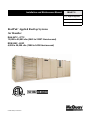
RoofPak® Applied Rooftop Systems
Air Handler
RAH 047C - 077C
12,000 to 50,000 cfm (5663 to 23597 liters/second)
RDS 800C - 802C
4,000 to 20,000 cfm (1888 to 9439 liters/second)
© 2002 McQuay International
IM-487
Page 1
Table of Contents
Introduction .......................................................................... 3
Receiving Inspection .........................................................3
Hazard Identification Information .....................................3
Nomenclature ....................................................................3
Typical Component Locations ......................................... 4
Typical Unit Sections ....................................................... 7
Control Locations ............................................................. 8
Control Panel Locations ................................................... 9
Controls, Settings, and Functions ................................... 13
Mechanical Installation ...................................................... 14
Unit Clearances ...............................................................14
Ventilation Clearance ..................................................... 15
Overhead clearance ..........................................................15
Roof Curb Assembly and Installation .............................16
Post and Rail Mounting .................................................. 18
Rigging and Handling ......................................................18
Split Units ........................................................................19
Reassembly of Split Units .............................................. 20
Installing Ductwork .........................................................22
Installing Duct Static Pressure Sensor Taps ....................22
Installing Building Static Pressure Sensor Taps ..............23
Condensate Drain Connection ........................................ 24
Field Refrigerant Piping and Charging of DX Coils .......25
Piping Recommendations ............................................... 25
Leak Testing ................................................................... 26
Evacuation .......................................................................26
Charging the System ........................................................26
Refrigerant Charge ..........................................................27
Unit Piping ..................................................................... 28
Vestibule Assembly Instructions .................................... 33
Damper Assemblies ........................................................ 35
Cabinet Weatherproofing ................................................39
Electrical Installation ......................................................... 40
Field Power Wiring .........................................................40
Field Control Wiring .......................................................42
Preparing Unit for Operation ............................................. 43
Relief Damper Tie-Down ................................................43
Spring Isolated Fans ........................................................43
Adjustment of Seismic Restraints ...................................44
Adjustment of Scroll Dampers ........................................45
Sequences of Operation ..................................................... 46
Power-up ..........................................................................46
Fan Operation ..................................................................46
Economizer Operation .....................................................46
Heating ............................................................................47
Wiring Diagrams ................................................................ 48
Typical Control Circuit with Power Pack Only ..............50
Page 2
Typical Power Circuits .................................................... 50
Typical Compressor Staging Outputs .............................51
Typical Main Control Circuit (VAV Units) ....................52
Typical Main Control Schematic (CAV Units) ..............54
Typical Actuator Circuit .................................................56
Typical Supply/Return Fan Control Circuit ....................57
Typical Gas Furnace Control Circuit
(Modulating Burner, Mixed Air Intake) .........................58
Typical Electric Heat Control Circuit (Multi-Stage) ......59
Unit Options ........................................................................60
Enthalpy Control ............................................................. 60
External Time Clock ....................................................... 60
Smoke Detectors ............................................................. 60
Freeze Protection ............................................................. 61
Mixed Air Temperature Alarm ....................................... 61
Duct High Pressure Limit ................................................ 61
Variable Inlet Vanes ........................................................ 61
Actuator Rotation Adjustment ........................................ 62
Variable Frequency Drive Operation ..............................67
Convenience Receptacle/Section Lights ......................... 67
DesignFlow Outdoor Air Damper Option ....................... 67
Propeller Exhaust Fan Option ......................................... 69
Propeller Exhaust Fan Control ........................................72
Before Start-up ................................................................ 73
Power-up ......................................................................... 73
Fan Start-up ..................................................................... 73
Economizer Start-up ........................................................ 74
Heating System Start-up .................................................. 74
Cooling System Start-up ................................................. 74
Adjusting MicroTech II Controls and Servicing Control
Panel Components ........................................................... 75
Air Balancing .................................................................. 75
Sheave Alignment ...........................................................75
Drive Belt Adjustment .................................................... 76
Mounting and Adjusting Motor Sheaves ........................ 77
Final Control Settings .........................................................80
Maintenance ........................................................................84
Planned Maintenance ..................................................... 84
Unit Storage ..................................................................... 84
Gas Furnace ..................................................................... 85
Bearing Lubrication ......................................................... 85
Airfoil Supply Fan Wheel-to-Funnel Alignment ............ 86
Winterizing Water Coils .................................................. 87
Standard Limited Product Warranty ...................................87
Service and Warranty Procedure ........................................87
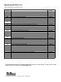
Replacement Parts List .......................................................88
IM-487
Introduction
This manual provides general information about the "C" vintage McQuay RoofPak® applied rooftop unit, models RAH,
and RDT. In addition to an overall description of the unit, it
includes mechanical and electrical installation procedures,
commissioning procedures, sequence of operation information, and maintenance instructions. For further information
on the optional forced draft gas-fired furnace, refer to Bulletin No. IM 684 or IM 685.
The MicroTech II ™ applied rooftop unit controller is available on "C" vintage applied rooftop units. For a detailed
description of the MicroTech II components, input/output
configurations, field wiring options and requirements, and
service procedures, refer to IM696 for a description of operation and information on using and programming the MicroTech II unit controller, refer to the appropriate operation
manual (See Table 1).
For a description of operation and information on using the
keypad to view data and set parameters, refer to the appropriate program-specific operation manual. (See Table 1).
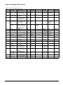
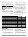
Table 1: Program Specific Rooftop Unit Operation Literature
Rooftop Unit
Control Configuration
Operation Manual
Bulletin Number
VFD’s
Vendor IM Manuals
Discharge Air Control (VAV or CAV)
OM 137
Space Comfort Control
(CAV-Zone Temperature Control)
OM 138
Receiving Inspection
When the equipment is received, check all items against the
bill of lading to be sure all crates and cartons have been
received. If the unit has become dirty during shipment
(winter road chemicals are of particular concern), clean it
when received.
Inspect all units for damage when received. Report all shipping damage to the carrier and file a claim. In most cases,
equipment is shipped F.O.B. factory and claims for freight
damage should be filed by the receiver.
The unit nameplate should be checked before unloading the
unit to make sure the voltage complies with the power supply
available.
Hazard Identification Information
WARNING
Warnings are provided throughout this manual to indicate
to installing contractors, operators, and service personnel
potentially hazardous situations which, if not avoided,
can result in severe personal injury or property damage.
CAUTION
Cautions are provided throughout this manual to indicate
to installing contractors, operators, and service personnel
potentially hazardous situations which, if not avoided,
can result in personal injury or equipment damage.
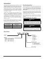
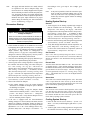
Nomenclature
R AH — 047 C S E
RoofPak
Unit Size
RDS 800 = 4000 - 16000 CFM
RDS 802 = 8000 - 20000 CFM
RAH 47 = 12000 - 30000 CFM
RAH 77 = 23000 - 50000 CFM
Heat Medium
A = Natural Gas
E = Electric
F = Fuel Oil
S = Steam
W = Hot Water
Y = None
Cooling Coil Size
S = Standard (Low Airflow)
L = Large (High Airflow)
Y = None or Contractor Coil
Design Vintage
IM-487
Page 3
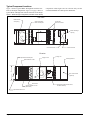
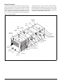
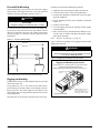
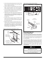
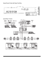
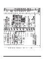
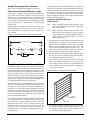
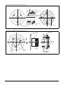
Typical Component Locations
Figure 1 shows a typical Blow-Through unit with the locations of the major components. Figure 2 on page 5 shows a
typical Draw-Through unit with the locations of the major
components. These figures are for reference only. See the
certified submittals for actual specific dimensions.
Figure 1. Blow-Through Configuration (Unit Size 077C Shown)
Plan View
Bottom Return
Air Opening
Optional Outside &
Return Air Dampers
Condensate
Drain Connections
Bottom Discharge
Opening
Control Entrances
Power Entrances
Elevation
Optional Exhaust Dampers
Optional Return Air Fan
Cooling Coil
Supply Air Fan
Discharge Plenum
C
Main Control Panel
(Optional)
D
Filter Section
Optional Outside Louvers
(Both Sides)
Heat Section (Natural Gas, Steam,
Hot Water, Electric)
Optional Back Return Air
Page 4
IM-487
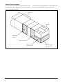
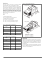
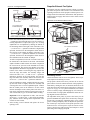
Figure 2. Draw-Through Configuration with SWSI Supply Fan (Unit Size 077C Shown)
Plan View
Bottom Return
Air Opening
Optional Outside &
Return Air Dampers
Bottom Discharge
Opening
Condensate
Drain Connection
Control Entrances
Power Entrances
Elevation
Optional Exhaust Dampers
Optional Return Air Fan
Steam/Hot Water
Supply Air Fan
C
D
Filter Section
Optional Outside Louvers
(Both Sides)
Main Control Panel
(Optional)
Optional Back Return Air
IM-487
Page 5
Figure 3. Combination Draw-Through / Blow-Through with DWDI Supply Fan
Plan View
Condensate
Drain Connection
Bottom Return
Air Opening
Control Entrances
Power Entrances
Bottom Discharge
Opening
Elevation
Heating/Cooling Coil
Discharge Plenum
Mixing Box
Supply Air Fan
C
Filter Section
Final Filter
Cartridge
Fresh Air Hood
Main Control Panel
(Optional)
Heat Section (Natural Gas, Steam
Hot Water, Electric)
Page 6
IM-487
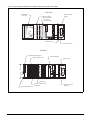
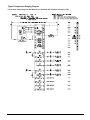
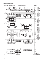
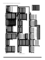
Typical Unit Sections
The individual sections that make up a rooftop can vary from unit to unit. All available sections are shown
in Figure 4 and Figure 5.
Figure 4. Typical Unit Sections (Draw-Through and Blow-Through with DWDI Supply Fan)
RETURN
AIR
OA/HOOD
COIL
FILTER
COIL
DP ONLY
DP ONLY
TA/30
HEAT
FLAT
PLENUM
65/95
MWU
HEAT
OPT
EVAP
COIL
S & HW
S & HW
OPT
BLANK
STAGG
FLAT
STAGG
ELEC
STAGG
BLANK
STAGG
ECONO
PLEN
OPT BLANK
OUTSIDE
AIRSTREAM
SA FAN
STAGG
30% OA
FLAT
OPT
FINAL
FILTER
STAGG
BLANK
GAS
BLANK
STAGG
ECONO/RA
BLANK
STAGG
BLANK
BLANK
STAGG
MIXING BOX
BLANK
STAGG
Figure 5. Typical Unit Sections (Draw-Through with SWSI Supply Fan)
RETURN
AIR
OA/HOOD
COIL
FILTER
DP ONLY
TA/30
FLAT
PLENUM
65/95
OPT
EVAP
COIL
S & HW
STAGG
30% OA
STAGG
OPT BLANK
OUTSIDE
AIRSTREAM
MWU
HEAT
SA FAN
BLANK
STAGG
ECONO
BLANK
BLANK
STAGG
ECONO/RA
BLANK
MIXING BOX
STAGG
Note: Views shown for 047C family. Not to scale
IM-487
Page 7
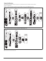
Control Locations
“Wiring Diagrams” on page 48. Figure 6 shows the blowthrough heat and blow-through coil sections. These sections
are also available in the draw-through position. All controls
mounted in the blow-through section would be located in the
same position within the draw-through section.
All controls are optional. If controls are ordered, Figure 6
shows the locations of various control components mounted
throughout the unit. See “Control Panel Locations” on page 9
for the locations of control components mounted in control
panels. Additional information is included in Table 2 on
page 13 and the wiring diagram legend at the beginning of
Figure 6. Control Locations
Discharge
Plenum
Section
Heat
Section
DX
Section
Supply
AC1
Fan
(Optional)
Section
Filter
Section
Return Air
Economizer
SV2
SV1
SV5 (Optional)
SV6 (Optional)
CAT
DAT
VM1 (Optional)
SD1 (Optional)
EAT
PC7
HL22 (Optional)
LT10 (Optional)
S10, REC10 (Optional)
AC1
(Optional)
ACT3 PC5
SD2
(Optional)
OEA
RAT
LT11
(Optional)
S11, REC11
Note: See the wiring diagrams legend at the beginning of “Wiring Diagrams” on page 48 for designation /description.
Page 8
IM-487
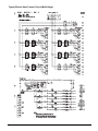
Control Panel Locations
The unit control panels and their locations are shown in the
following figures. These figures show a typical unit configu-
ration. Specific unit configurations may differ slightly from
these figures depending on the particular unit options.
Figure 7. Control Panel Locations
Supply Fan
Section
Condenser
Section
Electric Heat
Control Panel
(Optional)
Main Control Panel
Condenser Control
Panel (015 - 030)
IM-487
Condenser Control
Panel (036 - 075)
Page 9
Figure 8. Main Control Panel Power Pack Only
FB20
FB10
Note: See the wiring diagrams legend at the beginning of “Wiring Diagrams” on page 48 for designation /description.
Page 10
IM-487
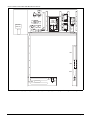
Figure 9. Main Control Panel with MicroTech II Controls
F 3
T 3
T B 6
T 2
E H B # 1
K E Y P A D
D IS P L A Y
R
6 8
R R R R
4 9 4 8 4 7 4 6
R 3 0
R 6 7
R
2 8
R 2 7
R 2 6
R 2 0
T D 1 9
R
2 4
A N A L O G
R
6 9
IN P U T S
B IN A R Y IN P U T S
N B 1
M
B A
L O N
C
C
M C
M A
C T
B O A
S T
C N
W O
O M
A R
B
IN
R L
R D
P E T E T H E R N E T
C O M M
R K S
C A R D
M
D
C C B # 1
E R B # 1
D H L
T D 9
T B 5
T B 8
T B 1 0
T B 2
S P S 2
T B 2
S P S 1
N B 2
Note: See the wiring diagrams legend at the beginning of “Wiring Diagrams” on page 48 for designation /description.
IM-487
Page 11
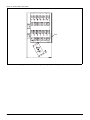
Figure 10. Electric Heat Control Panel
TB11
Note: See the wiring diagrams legend at the beginning of “Wiring Diagrams” on page 48 for designation /description.
Page 12
IM-487
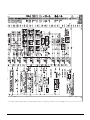
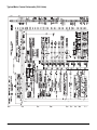
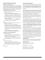
Controls, Settings, and Functions
Table 2: Controls, settings and functions
SYMBOL
DESCRIPTION
DAT
Discharge air
temperature sensor
DHL
Duct high limit
switch
EFT
FS1
OAE
FUNCTION
RESET
Senses discharge air
N/A
temperature.
Prevents excessive VAV duct Auto
pressures; shuts off fan.
Entering fan air
Senses entering fan air
N/A
temperature sensor temperature
Freezestat
Shuts off fans, opens heating Auto
valve and closes outdoor
damper if low air temperature
at coil is detected.
Enthalpy control
Returns outside air dampers Auto
(electromechanical) to minimum position when
enthalpy is too high.
Enthalpy control
(electronic)
PC5
Returns outside air dampers
to minimum position when
outside air enthalpy is higher
than return air empalthy
(use RAE)
Outside air
Senses outside air
temperature sensor temperature.
Dirty Filter switch
Senses filter pressure drop.
Auto
PC6
Dirty Filter switch
Senses filter pressure drop.
Auto
PC7
Air flow proving
switch
Return air enthalpy
sensor
Senses supply fan pressure
to prove airflow.
Used to compare return air
enthalpy to outside air
enthalpy (used with OAE).
Return air
Senses return air
temperature sensor temperature.
Smoke detector,
Initiates unit shutdown if
supply air
smoke is detected.
Smoke detector,
Initiates unit shutdown if
return air
smoke is detected.
Static Pressure
Converts static pressure
Sensor Duct # 1
signals to voltage signals.
Auto
OAT
RAE
RAT
SD1
SD2
SPS1
SPS2
S1
S7
IM-487
Static Pressure
Sensor Duct # 2
Static Pressure
Sensor: Building
(Space) Pressure
System Switch
ON-OFF-AUTO
switch
Auto
LOCATION
Discharge air
section
Main control
panel
RANGE
3K ohms at
77°F (25°C)
0.05-5.0” w.c.
(12.5-1245.4 Pa)
DIFFERENTIAL
PART NO.
N/A
060004705
.05" w.c.
(12.5 Pa), fixed
065493801
Inlet of supply N/A
fan
Heating
38°F (3°C)
section
or as required
3K ohms
at 77°F (25°C)
35°F - 45°F
(2°C - 7°C)
N/A
060004705
Economizer
section
"B" or as required
A—D
030706702
Economizer
section
Fully CW past "D"
(when used
with RAE)
A—D
Temperature:
3.5°F (2°C)
Humidity:
5% fixed
N/A
N/A
3K ohms at
77°F (25°C)
.05-5” w.c.
(12.5-1245.4 Pa)
.05-5” w.c.
(12.5-1245.4 Pa)
.05-5” w.c.
(12.5-1245.4 Pa)
N/A
N/A
060004705
.05” w.c.
(12.5 Pa)
.05” w.c.
(12.5 Pa)
.05” w.c.
(12.5 Pa), fixed
N/A
065493801
N/A
N/A
N/A
Manual
Manual
N/A
Converts static pressure
N/A
signals to voltage signals and
sends them to MicroTech II
controller.
Converts static pressure
N/A
signals to voltage signals.
Shuts off entire control circuit N/A
(except crankcase heaters)
Used to manually switch unit. N/A
First Filter
section
Final Filter
section
Supply fan
section
Economizer
section
SETTING
N/A
3.5” w.c (871.8 Pa)
As required
As required
.10" w.c. (25 Pa)
N/A
Return air
section
Discharge air
section
Return air
section
Main control
box
N/A
Main control
box
N/A
Main control
box
N/A
Main control
box
Main control
box
12°F (7°C), fixed 065830001
049262201
065493801
060015801
049262202
N/A
060004705
N/A
3K ohms at
77°F (25°C)
N/A
N/A
04925001
N/A
N/A
N/A
04925001
N/A
0—5” w.c.
(0—1245.4 Pa)
1—6 VDC out
0—5” w.c.
(0—1245.4 Pa)
1—6 VDC out
N/A
049545005
N/A
049545005
049545006
N/A
-025—0.25” w.c. N/A
(-62.3—62.3 Pa)
1—5 VDC out
N/A
N/A
N/A
N/A
001355000
N/A
Page 13
Mechanical Installation
The installation of this equipment shall be in accordance with
the regulations of authorities having jurisdiction and all
applicable codes. It is the responsibility of the installer to
determine and follow the applicable codes.
WARNING
Sharp edges on sheet metal, screws and clips can
cause personal injury.
WARNING
This equipment must be installed and operated only by
experienced trained personnel.
Sharp edges and coil surfaces can cause personal
injury. Avoid contact with them.
Unit Clearances
Installation and maintenance must be performed only by
trained and experienced personnel familiar with local
codes and regulations.
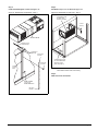
Service Clearance
Allow service clearance approximately as indicated in
Figure 11. Also, provide a roof walkway rooftop unit and
along at least the two sides of the unit that provide access to
most controls and serviceable components.
Figure 11. Service Clearances - Unit with Housed DWDI Supply Fan
72"
(1829 mm)
B
A
72"
(1829 mm)
C
D
D
E
C
F
24"
(635 mm)
60"
(1524 mm)
Roof
Walkway
X
Legend:
A = Return Air Section
B = Filter Section
C = Cooling Section
D = Cooling/Supply Fan Section
E = Heat Section
F = Discharge Plenum Section
Varies With Unit Arrangement
Refer to Certified Drawing & Note
To Roof
Access
Location
Note:
Sections with heating and/or cooling coils or DWDI
supply fan must have noted service clearance on the
control box side.
Dimension "X"
RDS 800-802 = 90" (2286mm)
RAH 47-77 = 96" (2438mm)
Figure 12. Service Clearances - Unit with SWSI Plenum Supply Fan
72"
(1829 mm)
A
72"
(1829 mm)
60"
(1524 mm)
Roof
Walkway
B
C
D
E
96"
(2438 mm)
To Roof
Access
Location
Varies With Unit Arrangement
Refer to Certified Drawing & Note
Note:
Sections with heating and/or cooling coils or DWDI
supply fan must have noted service clearance on the
control box side.
Page 14
X
Legend:
A = Return Air Section
B = Filter Section
C = Cooling Section
D = Cooling/Supply Fan Section
E = Heat Section
F = Discharge Plenum Section
Dimension "X"
RDS 800-802 = 90" (2286mm)
RAH 47-77 = 96" (2438mm)
IM-487
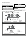
Ventilation Clearance
Overhead clearance
Following are minimum ventilation clearance recommendations. The system designer must consider each application
and provide adequate ventilation. If this is not done, the unit
will not perform properly.
1. Unit(s) surrounded by screens or solid walls must have no
overhead obstructions over any part of the unit.
Unit(s) surrounded by a screen or a fence:
1. The bottom of the screen or fence should be at least 1 ft.
(305 mm) above the roof surface.
2. The distance between the unit and a screen or fence
should be as described in “Service Clearance” on page
14. See also Figure 11 on page 14.
3. The distance between any two units within a screen or
fence should be at least 120" (3048 mm).
Unit(s) surrounded by solid walls:
1. If there are walls on one or two adjacent sides of the unit,
the walls may be any height. If there are walls on more
than two adjacent sides of the unit, the walls should not be
higher than the unit.
2. The following restrictions must be observed for overhead
obstructions above the air handler section (see Figure 13):
a. There must be no overhead obstructions above the furnace flue, or within 9" (229 mm) of the flue box.
b. Overhead obstructions must be no less than 2" (51 mm)
above the top of the unit.
c. There must be no overhead obstructions in the areas
above the outside air and exhaust dampers that are farther than 24" (610 mm) from the side of the unit.Side
Discharge.
2. The distance between the unit and the wall should be at
least 96" (2438 mm) on all sides of the unit.
3. The distance between any two units within the walls
should be at least 120" (3048 mm). Do not locate outside
air intakes near exhaust vents or other sources of contaminated air.
If the unit is installed where windy conditions are common,
wind screens should be installed around the unit, maintaining
the clearances specified (see Figure 13). This is particularly
important to prevent blowing snow from entering outside air
intakes, and to maintain adequate head pressure control when
mechanical cooling is required at low outdoor air temperatures.
Side Discharge Opening
(Access in Ductwork
Must be Removed)
NOTICE
On units with side discharge, access to plenum mounted
components becomes difficult once ductwork is installed.
Installer must provide access in the ductwork for plenum
mounted controls.
Figure 13. Overhead Clearance
Overhead
Canopy
9" (229 mm)
Minumum to Flue Box
Typical All Sides
24" (610 mm)
Maximum
Flue Box
2" (51 mm)
Minumum
Top of Unit
to Overhead
Obstruction
24" (610 mm)
Maximum
IM-487
Page 15
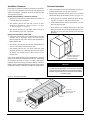
Roof Curb Assembly and Installation
work to the curb before the unit is set. The gasketed top
surface of the duct flanges seals against the unit when it is set
on the curb. These flanges must not support the total weight
of the ductwork. Refer to “Installing Ductwork” on page 22
for details on duct connections. Assembly of a typical RAH
roof curb is shown in. Parts A through H are common to all
units having bottom return openings. Depending on the unit
length, Parts L and M may be included with the roof curb kit
to create the correct overall curb length.
Locate the roof curb and unit where the roof can support the
weight. Support the unit to prevent bending or twisting of the
machine. If the building allows sound and vibration into the
occupied space, locate the unit over a non-critical area. It
is the responsibility of the system designer to make adequate provisions for noise and vibration in the occupied
space. Install the curb and unit level to allow the condensate
drain to flow properly with absolutely no pitch away from
the drain. Integral supply and return air duct flanges are provided with the RAH roof curb, allowing connection of ductFigure 14. RAH Roof Curb Assembly Instructions
M
L
3.50"
(90 mm)
8.75"
(222 mm)
Using remaining side supports
in this area, align lengths on
opposite sides of assembly
and install a cross support
"D" at each side.
Detail A
81.00"
(2057 mm)
Inside
A
"Y"
Inside
D
G
C
M
H
Equal Length
Side Supports
H
L
7.50"
(191 mm)
Supply
Air
2.00"
(51 mm)
G
D
B
C
"X"
Inside
70.75"
(1797 mm)
D
E
8.75"
(222mm)
F
F
3.50"
(90mm)
Return
Air
See Detail "A"
A
1. Unit Base
2. Curb Gasketing
3. 2 x 4 Nailer Strip
4. Galvanized Curb
5. Cant Strip (not furnished)
6. Roffing Material (not furnished)
7. Rigid Insulation (not furnished)
8. Counterflashing (not furnished)
9. Flashing (not furnished)
E
87.00"
(2210 mm)
Inside
B
90.00"
(2286 mm)
94.75"
(2407 mm)
Figure 15. Roofing Detail "B"
2
1
RAH Unit
"X"
"Y"
047C
38
(965)
28
(711)
077C with Flat Cooling Coil and /or 44"
SWSI Plenum Supply Fan
62
(1575)
38
(965)
077C with Staggered or No Cooling Coil,
and /or 49" SWSI Plenum Supply Fan
62
(1575)
46
(1168)
3
8
7
4
9
5
6
Dimensions In. (mm)
Main
Unit
Curb
Page 16
IM-487
Assembly Instructions:
1. Set curbing parts A thru H per dimensions shown over roof opening or on a level surface. Note location of return and supply air openings.
2. If applicable, set other curbing parts (D, L, M, etc.) in place making sure that the orientation agrees with the assembly instructions.
Check alignment of all mating bolt holes. See Detail "A".
3. Bolt curbing parts together using fasteners provided. Tighten all bolts finger tight.
4. Square entire curbing assembly and securely tighten all bolts.
5. Position curb assembly over roof openings. Curb must be level from side to side and over its length.
Check that top surface of the curb is flat with no bowing or sagging.
6. Weld curbing in place. Caulk all seams watertight. Remove backing from 0.25 thick x 1.50 wide gasketing and apply to surfaces shown by crosshatching.
7. Flash curbing into roof as shown in Detail "B".
8. Parts E and F are not required on units with no return shaft within the curb perimeter.
9. Parts G and H are not required on units with no supply shaft within curb perimeter.
Figure 16. RDS Roof Curb Assembly Instructions
6.80"
(173 mm)
1.50"
(38 mm)
20.00"
(508 mm)
Inside
76.00" (1930 mm)
Inside
G
C
A
H
H
D
7.50"
(191 mm)
Supply
Air
2.00"
(5.1 mm)
G
B
C
"X"
Inside
38.80"
(984 mm)
D
E
F
"XX"
F
"YY"
Return
Air
See Detail "A"
A
E
"Y"
Inside
B
85.00"
(2159 mm)
62.80"
(1594 mm)
“X”
"Y"
"XX"
"YY"
RETURN
FAN
IN.
MM
IN.
MM
IN.
MM
IN.
MM
NONE
24.0
610
82.0
2083
6.8
173
1.5
38
(2) 15" FC
24.0
610
82.0
2083
6.8
173
1.5
38
30" AF
30.0
762
76.0
1930
6.8
173
4.5
114
40" AF
36.0
914
78.0
1981
14.8
376
3.5
89
IM-487
Page 17
Post and Rail Mounting
mediate period, take these additional precautions:
When mounting by post and rail, the structural support
should run the full length of the unit. Locate the structural
member at the base of the unit as shown in Figure 17.
1. Support the unit well along the length of the base rail.
CAUTION
The unit must be level side to side and over the
entire length.
Equipment damage can result if the unit is not level.
If resilient material is placed between the unit and the rail,
insert a heavy steel plate between the unit and the resilient
material to distribute the load. Seal cabinet penetrations
(electrical, piping, etc.) properly to protect against moisture
and weather.
Figure 17. Post and Rail Mounting
5" *
(127mm)
99" RAH
(2515 mm)
94" RDS
(2388 mm)
2. Level the unit (no twists or uneven ground surface).
3. Provide proper drainage around the unit to prevent flooding of the equipment.
4. Provide adequate protection from vandalism, mechanical
contact, etc.
5. Securely close the doors.
6. Cover the supply and return air openings on units without
isolation dampers.
7. Fully close the factory installed isolation dampers to prevent the entry of animals and debris through the supply
and return air openings.
Note:
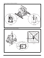
Refer to “Unit Storage” on page 84.
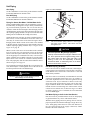
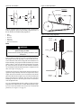
Figure 18 shows an example of the rigging instruction label
shipped with each unit.
WARNING
Use all lifting points.
Severe personal injury and property damage can result
from improper lifting adjustment.
Figure 18. Rigging and Handling Instruction Label
Rigging and Handling Instructions
Unit has either four or six lifting points (four-point shown below).
Caution: All lifting points must be used.
Note: Rigging cables must be at least as long as distance "A".
Spreader Bars
Required
Maximum recommended width for structural member is 5" (127 mm) to
allow for adequate space for duct connections and electrical entry.
Rigging and Handling
Lifting brackets with 2" (51 mm) diameter holes are provided
on the sides of the unit.
A
Use spreader bars, 101" to 105" (2565 to 2667 mm) wide to
prevent damage to the unit cabinet. Avoid twisting or uneven
lifting of the unit. The cable length from the bracket to the
hook should always be longer than the distance between the
outer lifting points.
Lift Only As Indicated
Caution: Lifting points may not
be symmetrical to center of
gravity of unit. Balast or unequal
cable lengths may be required
If the unit must be stored at the construction site for an inter-
Page 18
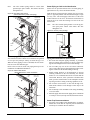
IM-487
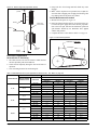
Lifting Points
Use Table 3 & Table 4 and Figure 19 to determine lifting
cable lengths and if four or six-pint lifting is required.
Figure 19. Unit Type RAH Lifting Points
4 Lifting Points
Refer to Figure 19 and note that dimension A is the distance
between the outer lifting points. The four outer rigging cables
must be equal to or longer than dimension A. Dimension B
shows the minimum distance between the outer and the inner
lifting points for six-point lifting. This can be used to roughly
determine the required length of the middle cables for sixpoint lifting. Dimension A can be determined by subtracting
dimensions X and Y from dimension Z.
(i.e., A = Z - X).
A
Where:
Z
X
Z =Total unit length in inches
(refer to certified drawings for this dimension).
X =Outdoor/return air section length
(refer to Table 3 for this dimension).
If A ≤ 288" (7315 mm), 4-point lifting is sufficient.
If A > 288" (7315 mm), 6-point lifting is required.
6 Lifting Points
Table 3: RAH "X" Dimension (see Figure 19)
Type of Economizer
047C
077C
100% OA
0
0
Plenum
48” (1219 mm)
72” (1829 mm)
0- 30% OA
48” (1219 mm)
72” (1829 mm)
0 - 100% Economizer
72” (1829 mm)
96” (2438 mm)
0 - 100% Economizer
With Return Fan
72” (1829 mm)
96” (2438 mm)
Section
A
B
Z
X
RDS 800: B Min. = 62" (1515 mm)
RDS 802: B Min. = 84" (2134 mm)
RAH 47: B Min. = 96" (2438 mm)
RAH 77: B Min. = 120" (3048 mm)
Table 4: RDS "X" Dimension (see Figure 19)
Outdoor/Return Air
Section
800C
802C
100% OA
0
0
Plenum
40” (1016 mm)
52" (1321 mm)
0- 30% OA
40” (1016 mm)
52" (1321 mm)
0 - 100% Economizer
40” (1016 mm)
52" (1321 mm)
0 - 100% Economizer
With 15" Return Fan
62" (1575 mm)
—
0 - 100% Economizer
With 30" Return Fan
52" (1321 mm)
52" (1321 mm)
0 - 100% Economizer
With 40" Return Fan
—
80" (2032 mm)
IM-487
Split Units
Although units typically ship from the factory as complete
units, they can be factory split at the supply fan bulkhead and
connected later on the roof. This configuration is ordered if
the shipping length or a weight limitation prevents ordering a
packaged unit.
A single nameplate is attached to the air handler section and
power is supplied to both sections through the optional main
control box as in a packaged unit.
Page 19
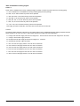
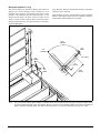
Reassembly of Split Units
Field reassembly of a unit shipped split at the fan takes place
in two places:
junction box, per the unit's electrical schematics.
1. Setting the sections and mechanically recoupling
the cabinet.
WARNING
Connect the power block correctly and maintain
proper phasing.
2. Reconnecting power and control wiring if optional power
pack and/or controls are used.
Setting the Sections and Cabinet Reassembly
Steps 1 to 5 describe what is required to set the unit and reassemble the cabinet. Note also the following items:
•
Top cap and plywood covers must be removed before the
sections are set together, but the steel retainer clips must
be left in place to secure the bulkhead. Refer to Step #1
and Figure 20.
•
Both sections must be lowered into place carefully to
make sure that the roof curb engages the recesses in the
unit base.
•
All seams at the split must be caulked watertight after
recoupling the sections, as shown in Step #3 and
Figure 21 on page 21.
Reconnecting Power and Control Wiring
(Units With Optional Factory Wiring)
The discharge sections contain power and control harnesses
which have their excess length in the blank or heat section
that is normally immediately downstream of the fan. Once
the sections are physically reconnected, the ends of the
power harness are fed back through the unit base into the
Improper installation can cause severe equipment damage, personal injury or death.
After the power wires are reconnected, the inner raceway
cover in the blank or heat section must be reinstalled. Step 4
of Figure 22 on page 21 shows a typical installation of a
raceway cover.
Run control harnesses by removing the external raceway
covers on either side of the unit. Excess harness may be
removed from the external raceway on the discharge side of
the split, routed along the raceway through the brushed hole
in the fan section, and into the junction box where control
wiring terminal blocks are provided for reconnection. Make
electrical connections using the unit’s electrical schematics.
Reinstall the external raceway covers after the control wires
are routed.
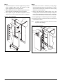
Step 1.
Prepare units for reassembly as shown in Figure 20.
Step 2.
Set fan end of unit and discharge end of unit in place.
Figure 20. Reassembly of Split Unit - Step 1
Remove top cap and
save for step 3
Fan end of Unit
Page 20
Discharge end of Unit
Remove screws on fan panel, but
leave retainer clips in place;
save screws for Step 3.
Remove plywood and retaining
angles from unit and discard
IM-487
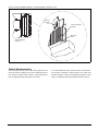
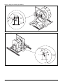
Step 3.
Caulk and install parts as shown in Figure 21.
Step 4.
Install Raceway Cover as shown in Figure 22.
Figure 21. Reassembly of Split Units - Step 3
Figure 22. Reassembly of Split Units - Step 4
If applicable install
as shown with
fasteners provided.
3.72 ref.
(94 mm)
SEE DETAIL BELOW
Reinstall Top Cap
saved from step 1
Caulk Ends of
Splice Cap
Splice Cover
Provided
#10 Screws
Provided
Caulk
Vertical
Seam
Inner Raceway Cover
is to be installed after
wires are routed
(Note: See Step 5)
Note:
Use the diffuser in a blank heat section or in a steam
heat and hot water heat section only.
Step 5.
Make electrical connections.
INSTALL SCREWS
(.25 - 20 X .75)
SAVED FROM STEP 1
Nut Clip-on
Provided
IM-487
Page 21
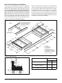
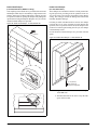
Installing Ductwork
On bottom-supply/bottom-return units, the installing contractor should make an airtight connection. Attach field fabricated duct collars to the bottom surface of either the roof
curb's duct flange or the unit's duct opening if a McQuay roof
curb is not used. Do not support the total weight of the ductwork from the unit or these duct flanges. Refer to Figure 23.
Units with optional back return, side discharge, or end discharge
(on RFS units) all have duct collars provided. The discharge
duct collars on a side discharge unit are exposed by removing
the plenum section access door and the door gasketing.
Where return air ducts are not required, connect a sound
absorbing T or L section to the unit return to reduce noise
transmission to the occupied space.
Build ductwork exposed to outdoor conditions in accordance
with ASHRAE and SMACNA recommendations and local
building codes.
NOTICE
Installer must provide access in the ductwork for
plenum mounted controls.
Use flexible connections between the unit and ductwork to
avoid transmission of vibration from the unit to the structure.
On units with side discharge, access to plenum mounted
components becomes difficult once ductwork is installed.
Design ductwork per ASHRAE and SMACNA recommendations to minimize losses and sound transmission.
Figure 23. Installing Ductwork
U n it D u c t O p e n in g
U n it B a s e
9 .7 6 "
4 .5 8 "
F le x ib le
C o n n e c to r
D u c tw o rk
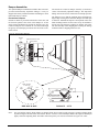
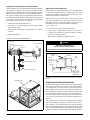
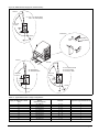
Installing Duct Static Pressure Sensor
Taps
For all VAV units, duct static pressure taps must be field
installed and connected to the pressure sensors in the unit.
Sensor SPS1 is standard; additional sensor SPS2 is optional.
These sensors are located at the bottom of the main control
panel next to terminal block TB2 (see “Control Panel Locations” on page 9).
The duct static pressure sensing tap must be carefully located
and installed. Improper location or installation of the sensing
tap will cause unsatisfactory operation of the entire variable
air volume system. Following are pressure tap location and
installation recommendations. The installation must comply
with local code requirements
Page 22
R o o f C u rb
D u c t F la n g e r
in R o o f C u r b
.
CAUTION
Fragile sensor fittings.
May damage pressure sensor.
If tubing must be removed from a pressure sensor fitting,
use care. Do not wrench the tubing back and forth to
remove or the fitting may break off.
1. Install a tee fitting with a leak-tight removable cap in each
tube near the sensor. This will facilitate connecting a
manometer or pressure gauge if testing is required.
2. Use different colored tubing for the duct pressure (HI) and
reference pressure (LO) taps, or tag the tubes.
IM-487
3. Locate the duct pressure (HI) tap near the end of a long
duct to verify that all terminal box take-offs along the run
will have adequate static pressure.
Figure 25. Pressure Sensing Tubing Installation
C o n d e n s e r S e c tio n
M a in C o n tr o l P a n e l
4. Locate the duct tap in a nonturbulent flow area of the duct.
Keep it several duct diameters away from take-off points,
bends, neckdowns, attenuators, vanes, or other irregularities.
5. Use a static pressure tip (Dwyer A302 or equivalent) or the
bare end of the plastic tubing for the duct tap. (If the duct is
lined inside, use a static pressure tip device.)
6. Install the duct tap so that it senses only static pressure (not
velocity pressure). If an L-shaped pressure tip device is
used, the point must face the airstream. If a bare tube end
is used, it must be smooth, square (not cut at an angle), and
perpendicular to the airstream.
(see Figure 25).
7. Locate the reference pressure (LO) tap somewhere near
the duct pressure tap within the building (see Figure 24). If
the reference tap is not connected to the sensor, unsatisfactory operation will result.
8. Route the tubes between the curb and the supply duct, and
feed them into the unit through the knockout in the bottom
of the control panel (see Figure 24). Connect the tubes to
the appropriate 1/8 inch fittings on the sensors. Make sure
that the sensors do not support the weight of the tubing;
use tube clamps or some other means.
Figure 24. Static Pressure Tubing Entrance Location
M a in
C o n tro l
P a n e l
O u td o o r S ta tic
P r e s s u r e T u b in g
E n tr a n c e ( F ie ld C u t)
C o n tr o l W ir in g
R a c e w a y C o v e r
In d o o r S ta tic
P r e s s u r e T u b in g E n tr a n c e
" H I lin e "
" L O " lin e
S P S 1
R o o f
R e m o te S e n s e P o in t
T o S e n s o r
" H I" in p u t
D u c tw o rk
( R e m o te L o c a tio n )
R u b b e r
G ro m m e t
T u b in g E x te n d s
th ru A p p ro x . 1 /8 "
T o S e n s o r
"L O " In p u t
P r e s s u r e S e n s in g
T u b in g
Installing Building Static
Pressure Sensor Taps
If a unit has direct building static pressure control capability,
static pressure taps must be field installed and connected to
pressure sensor SPS2 in the unit. This sensor is located at the
bottom of the main control panel next to terminal block TB2
(see "Control Panel Locations" in the "Unit Description" section of this manual).
The two static pressure sensing taps must be carefully located
and installed. Improper location or installation of the sensing
taps will cause unsatisfactory operation. Following are pressure tap location and installation recommendations for both
building envelope and lab, or "space within a space," pressure
control applications. The installation must comply with local
code requirements.
CAUTION
Fragile sensor fittings.
May damage pressure sensor.
If tubing must be removed from a pressure sensor fitting,
use care. Do not wrench the tubing back and forth to
remove or the fitting may break off.
IM-487
Page 23
Building Pressurization Applications
1. Install a "T" fitting with a leak-tight removable cap in each
tube near the sensor. This will facilitate connecting a
manometer or pressure gauge if testing is required.
2. Locate the building pressure (HI) tap in the area that re
quires the closest control. Typically, this is a ground level
floor that has doors to the outside.
3. Locate the building tap so that it is not influenced by any
source of moving air (velocity pressure). These sources
may include air diffusers or outside doors.
4. Route the building tap tube between the curb and the supply duct, and feed it into the unit through the knockout in
the bottom of the control panel (see Figure 24 on page 23).
Connect the tube to the V4 inch HI fitting on sensor SPS2.
The sensor must not support the weight of the tubing; use
tube clamps or some other means.
5. Locate the reference pressure (LO) tap on the roof. Keep
it away from the condenser fans, walls, or anything else
that may cause air turbulence. Mount it high enough
above the roof so that it is not affected by snow. If the
reference tap is not connected to the sensor, unsatisfactory operation will result.
6. Use an outdoor static pressure tip (Dwyer A306 or equivalent) to minimize the adverse effects of wind. Place some
type of screen over the sensor to keep out insects. Loosely
packed cotton works well.
7. Route the outdoor tap tube out of the main control panel
through a small field-cut opening in the edge of the control
wiring raceway cover (see Figure 24 on page 23). Cut this
"mouse hole" in the vertical portion of the edge. Seal the
penetration to prevent water from entering. Connect the
tube to the 1/4 inch LO fitting on sensor SPS2.
Lab Pressurization Applications
1. Install a ”T” fitting with a leak-tight removable cap in each
tube near the sensor. This will facilitate connecting a
manometer or pressure gauge if testing is required.
2. Use different colored tubing for the controlled space pressure (HI) and reference pressure (LO) taps, or tag the tubes.
3. Regardless of whether the controlled space is positive or
negative with respect to its reference, locate the HI pressure tap in the controlled space. (The setpoint can be set
between -0.2 and 0.2" W.C.)
4. Locate the reference pressure (LO) tap in the area surrounding the controlled space. If the reference tap is not connected
to the sensor, unsatisfactory operation will result.
5. Locate both taps so that they are not influenced by any
source of moving air (velocity pressure). These sources
may include air diffusers or doors between the high and
low pressure areas.
7. Connect the tubes to the appropriate ¼ inch fittings on sensor SPS2. The sensor must not support the weight of the tubing; use tube clamps or some other means.
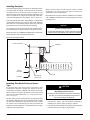
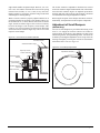
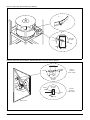
Condensate Drain Connection
The unit is provided with a 1.5" male NPT condensate drain
connection. Refer to certified drawings for the exact location.
The unit and drain pan must be level side to side and a P-trap
must be installed for proper drainage.
Units may have positive or negative pressure sections. It is
recommended that traps be used in both cases with care given
to negative pressure sections. In Figure 26 on page 25,
dimension "A" should be a minimum of 8" (203 mm). As a
conservative measure to prevent the cabinet static pressure
from blowing or drawing the water out of the trap and causing
air leakage, dimension "A" should be two times the maximum
static pressure encountered in the coil section in inches w.c.
Drainage of condensate directly onto the roof may be acceptable; refer to local codes. It is recommended that a small drip
pad of either stone, mortar, wood or metal be provided to protect the roof against possible damage.
If condensate is to be piped into the building drainage system,
pitch the drain line away from the unit at a minimum of 1/8"
per foot. The drain line must penetrate the roof external to the
unit. Refer to local codes for additional requirements. Sealed
drain lines require venting to provide proper condensate flow.
Where the cooling coils have intermediate condensate pans on
the face of the evaporator coil, copper tubes near both ends of
the coil provide drainage to the main drain pan. Check that
the copper tubes are in place and open before the unit is put
into operation.
On units with staggered cooling coils, the upper drain pan
drains into the lower coil drain pan through a copper tube
near the center of the drain pan. Check that this tube is
open before putting the unit into operation and as part of
routine maintenance.
Because drain pans in any air conditioning unit will have
some moisture in them, algae, etc. will grow. Periodic cleaning is necessary to prevent this buildup from plugging the
drain and causing the drain pan to overflow. Keep the drain
pans clean to prevent the spread of disease. Cleaning should
be performed by qualified personnel.
WARNING
Clean drain pans regularly. Growth in uncleaned drain
pans can cause disease.
Cleaning must be done by trained and
experienced personnel.
6. Route the tap tubes between the curb and the supply duct,
and feed them into the unit through the knockout in the
bottom of the control panel (see Figure 24 on page 23).
Page 24
IM-487
Figure 26. Condensate Drain Connection
tion of interconnecting piping. The DX coil and condensing
unit are intended to be set at the same elevation, as close as
possible to each other to minimize refrigerant pressure drop.
Design piping to prevent liquid refrigerant carryover to the
compressor and to provide a continuous return of compressor
oil from the system.
CAUTION
The pounds of refrigerant in the system may exceed
the capacity of the condenser, depending on the
amount of refrigerant in the liquid lines between the
DX coil and the condensing unit.
S e e V ie w " A "
C o p p e r T u b e
( o n e e a c h e n d o f c o il)
S ta tic P r e s s u r e " P "
( in . w .o .)
D r a in P a n
N o te : D r a in lin e m u s t
n o t b e r u n h ig h e r
th a n th is le v e l
4 " (1 0 2 m m )
M in im u m
Refer to condenser manufacturer for information about
refrigerant capacity. Suitable means of containing the
refrigerant is required.
CAUTION
On systems with optional hot gas bypass, it is
important the bypass solenoid valve be located at
the condensing unit and not at the DX coil to prevent
liquid return and damage to the compressor.
Piping Recommendations
"A "
8 " (2 0 3 m m )
M in . o r 2 x " P "
M in im iz e T h is
D im e n s io n
8 EA M )
Field Refrigerant Piping and
Charging of DX Coils
Units that ship from the factory with DX coils installed do
not include refrigerant piping or refrigerant controls. The coil
assembly is ready for field connections at the distributors and
at the suction headers. Piping kits that provide the necessary
liquid and hot gas piping and control components are available for field installation. Field installed refrigerant piping
may exit the unit cabinet at one of the following locations:
1. Through the floor of the unit.
1. Use type K or L clean copper tubing. Clean and braze all
joints thoroughly with high temperature solder.
2. Base piping sizes on temperature/pressure limitations as
recommended in the following paragraphs. Under no circumstances base pipe size strictly upon coil or condensing
unit piping connection size.
3. Suction line piping pressure drop should not exceed the
pressure equivalent of 2°F (1°C), 3 psi (20.7 kPa) per 100
feet (30.5 m) of equivalent pipe length. After the suction
line size has been determined, check the vertical suction risers to verify that oil will be carried up the riser and back to
the compressor. Pitch the suction line(s) in the direction of
refrigerant flow and support adequately. Lines should be
free draining and fully insulated between the evaporator
and the compressor.
2. Through the discharge and bulkhead of the unit.
4. Check vertical suction risers to determine the minimum tonnage required to carry oil up suction risers of various sizes.
3. Through a cabinet door near the DX coil that is not
required for service areas.
5. Insulate suction lines inside the unit cabinet to prevent
condensation.
CAUTION
For any of the above cabinet penetrations, the hole
must be tightly sealed to prevent water or air leakage.
In preparing for field piping, the plastic plugs on the distributors must be removed and the copper caps at the suction
header connections must be unsweated.
Follow piping design, sizing, and installation information
presented in ASHRAE handbooks in the design and installa-
IM-487
6. Size the liquid line for a pressure drop not to exceed the
pressure equivalent of 2°F (1°C), 6 psi (41.4 kPa) saturated temperature.
Table 5: Minimum tonnage (R-22) to carry oil up suction
riser at 40°F saturated suction
LINE SIZE 1-1/8"
O.D.
MIN.
TONS
1.5
1-3/8"
1-5/8"
2-1/8"
2-5/8"
3-1/8"
3-5/8"
4-1/8"
2.5
3.8
7.6
13.10
20.4
29.7
41.3
Page 25
Leak Testing
In the case of loss of the nitrogen holding charge, check
the unit for leaks prior to charging the complete system.
Leak testing must be done to current EPA standards and
regulations. After making any necessary repair, evacuate
the system as described in the following paragraphs.
WARNING
Do not use oxygen to build up pressure.
Using oxygen to build up pressure can cause an explosion, resulting in severe personal injury or death.
Evacuation
After it has been determined that the unit is tight and there
are no refrigerant leaks, evacuate the system. Use a vacuum pump with a pumping capacity of approximately 3
cu.ft./min. and the ability to reduce the vacuum in the unit
to at least 1 millimeter (1000 microns).
1. Connect a mercury manometer or other type of micron
gauge to the unit at a point remote from the vacuum pump.
For readings below 1 millimeter, use an electronic or other
micron gauge.
2. The triple evacuation method is recommended and is particularly helpful if the vacuum pump is unable to obtain
the desired 1 millimeter of vacuum. The system is first
evacuated to approximately 29" (740 mm) of mercury.
Enough refrigerant vapor is then added to the system to
bring the pressure up to 0 pounds (0 microns).
3. Then the system is once again evacuated to 29" (740 mm)
of vacuum. This procedure is repeated three times. This
method can be most effective by holding system pressure
at 0 pounds (0 microns) for a minimum of 1 hour between
evacuations. The first pulldown will remove about 90% of
the noncondensables, the second about 90% of that
remaining from the first pulldown, after the third, only 1/
10 of 1% of noncondensables will remain.
Table 6 shows the relationship between pressure, microns,
atmospheres, and the boiling point of water.
To service liquid line components, the manual shutoff valve is
closed and refrigerant is pumped into the condenser.
Table 6: Pressure Vacuum Equivalents
ABSOLUTE PRESSURE ABOVE ZERO
VACUUM BELOW 1 ATMOSPHERE
MICRONS
MERCURY
(MM)
PSIA
MERCURY
(IN.)
APPROXIMATE
FRACTION OF
1 ATMOSPHERE
BOILING POINT
OF H2O AT EACH
PRESSURE oF (°C)
0
0
760.00
29.921
—
—
50
0.001
759.95
29,920
1/15,200
- 50 (-45)
100
0.002
759.90
29.920
1/7,600
- 40 (-40)
150
0.003
759.85
29.920
1/5,100
- 33 (-36)
200
0.004
759.80
29.910
1/3,800
- 28 (-33)
300
0.006
759.70
29.910
1/2,500
- 21 (-29)
500
0.009
759.50
29.900
1/1,520
- 12 (-24)
1,000
0.019
759.00
29.880
1/760
1 (-17)
2000
0.039
758.00
29.840
1/380
15 (-9)
4,000
0.078
756.00
29.760
1/189
29 (-2)
6000
0.117
754.00
29.690
1/127
39 (4)
8,000
0.156
752.00
29.600
1/95
46 (8)
10,000
0.193
750.00
29.530
1/76
52 (11)
15,000
0.290
745.00
29.330
1/50
63 (17)
20,000
0.387
740.00
29.130
1/38
72 (22)
30,000
0.580
730.00
28.740
1/25
84 (29)
50,000
0.967
710.00
27.950
1/15
101 (38)
100,000
1.930
660.00
25.980
2/15
125 (52)
200,000
3.870
560.00
22.050
1/4
152 (57)
500,000
9.670
260.00
10.240
2/3
192 (89)
760,000
14.697
0
0
1 Atmosphere
212 (100)
Charging the System
RCS units are leak tested at the factory and shipped with a
nitrogen holding charge. If the holding charge has been lost
due to shipping damage, charge the system with enough refrigerant to raise the unit pressure to 30 psig after first repairing
the leaks and evacuating the system.
1. After all refrigerant piping is complete and the system has
been evacuated, charge it as described in the following
paragraphs. Connect the refrigerant drum to the gauge
port on the liquid shutoff valve, and purge the charging
Page 26
line between the refrigerant cylinder and the valve. Then
open the valve to the midposition.
2. If the system is under a vacuum, stand the refrigerant
drum with the connection up, open the drum and break the
vacuum with refrigerant gas.
3. With a system gas pressure higher than the equivalent of a
freezing temperature, invert the charging cylinder and elevate the drum above the condenser. With the drum in this
position and the valves open, liquid refrigerant will flow
IM-487
into the condenser. Approximately 75% of the total requirement estimated for the unit can be charged in this manner.
4. After 75% of the required charge has entered the condenser, reconnect the refrigerant drum and charging line
to the suction side of the system. Again purge the connecting line, stand the drum with the connection side up, and
place the service valve in the open position.
Important: At this point, interrupt the charging procedure
and do prestart checks before attempting to complete the refrigerant charge.
Note:
Stamp the total operating charge on the unit nameplate for future reference.
Note:
Factory installed DX coils are intended for one
refrigerant circuit on unit size 800 and two refrigerant circuits containing identical weights of refrigerant on all other sizes. The values shown in Table 7,
Table 8 and Table 9 are for each circuit.
Note:
The total operating charge per circuit should not
exceed the pumpdown capacity per circuit, specified
by the condensing unit manufacturer.
Table 7: Approximate DX Coil Refrigerant Charge Per Circuit
DX Coil R-22 Charge (Lbs./Circuit)
Unit Size
Flat Coil
Staggered Coil
047C
3 x No. of DX Rows
3.5 x No. of DX Rows
077C
5 x No. of DX Rows
6.5 x No. of DX Rows
Refrigerant Charge
Factory installed DX coils are designed to use R-22. The
total system charge is the sum of these three values:
Table 8: Approximate Refrigerant Charge Per Circuit
Unit Size
Evaporator Coil (Lbs/Ckt/Coil Row)
802
3.30
802C*
2.45
1. Condensing unit charge. Refer to manufacturer’s data.
2. Evaporator coil charge. Refer to Table 7 and Table 8.
* The RDS 802C unit has two refrigerant circuits
3. Charge for the length of interconnecting piping installed
by field. Refer to Table 9.
Table 9: Weight of refrigerant R-22 in copper lines (pounds per 100 feet of Type L tubing)
Weight of Refrigerant, Lbs./100 Feet
O.D. Line Size
IM-487
VOL. Per 100 FT.
In Cubic Feet
Liquid @100°F
Hot Gas
@120°F Cond.
Suction Gas (Superheat to 85°F)
30°F
40°F
3/8"
0.054
3.84
0.202
0.052
0.077
1/2"
0.100
7.12
0.374
0.098
0.143
5/8"
0.162
7.12
0.605
0.158
0.232
7/8"
0.336
24.00
1.260
0.323
0.480
1-1/8"
0.573
40.80
2.140
0.550
0.820
1-3/8"
0.872
62.10
3.260
0.839
1.250
1-5/8"
1.237
88.00
4.620
1.190
1.770
2-1/8"
2.147
153.00
8.040
2.060
3.060
2-5/8"
3.312
236.00
12,400
3.180
4.720
3-1/8"
4.728
336.00
17.700
4.550
6.750
3-5/8”
6.398
456.00
24.000
6.150
9.140
4-1/8"
8.313
592.00
31.100
8.000
11.190
Page 27
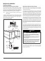
Unit Piping
Gas Piping
See the "Installation" section of the gas-fired furnace installation manual, Bulletin No. IM 684 or 685.
Figure 27. Valve Assembly
Fuel Oil Piping
See the "Installation" section of the gas-fired furnace installation manual, Bulletin No. IM 684 or IM 685.
S te m
Piping for Steam, Hot Water / ChIlled Water Coils
Factory installed chilled water coils are installed in a coil section which may be designed to accept a factory installed heating coil immediately upstream. The coil section may be
ordered in either the draw-through or blow-through position.
All chilled water piping can be done internal to the unit without requiring a piping vestibule (except on sizes 800-802 when
heating coils are included in the cooling coil section).
Steam and hot water coils may be factory installed in either a
heat section, or in the combination coil section. These sections may be located either in the draw-through or blowthrough position. When a steam or hot water coil is installed
in the heat section, all piping may be done internal to the unit
without requiring a piping vestibule. Refer to Figure 29 and
Figure 31 on page 30.
When a steam or hot water coil is installed in the combination coil section, the coil connections project to the inside
surface of the door panel. Holes may be cut in the door panels for the piping to be connected to the coils, or an accessory
piping vestibule may be added to the unit to provide piping
space. Refer to the section on vestibule assembly instructions. The piping may then be routed back within the unit as
shown in Figure 29 on page 29.
To avoid piping penetrations through the roof external to the
curb, holes may be cut through the floor of the unit at the
locations specified on the cer1ified drawings.
CAUTION
All holes in the unit floor must be sealed to prevent
water leakage into the building.
C lip
S te m
S e ts c re w s
Note:
The valve actuator spring returns to a stem up position upon power failure. This allows full flow
through the coil.
CAUTION
Coil freeze possible. May damage equipment.
Carefully read instructions for mixing the antifreeze solution. Some products will have higher freezing points in
their natural state than when mixed with water. The
freezing of coils is not the responsibility of McOuay
International. Refer 10 "Winterizing Coils" in the "Maintenance" section of the manual.
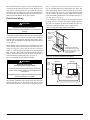
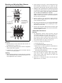
Hot Water Piping (All Units)
Note: If an iron valve is installed in the unit, connecting to a
copper piping system will likely cause galvanic corrosion to
occur and the valves will not last. All coils have vents and
drains factory installed.
Hot water coils are not normally recommended for use with
entering air temperatures below 40°F (4°C). No control system can be depended on to be 100% safe against freeze-up
with water coils. Glycol solutions or brines are the only
freeze-safe media for operation of water coils for low entering air conditions. Refer to the "Maintenance" section of this
manual for more on winterizing coils. The hot water section
consists of two stacked coils, as shown in Figure 28. When
no factory piping or valve is included, the coil connections
are 2.12" ODM copper.
Hot Water Piping to Coils In the Heat Section
Hot water coils are provided without valves for field piping,
or piped with three-way valves with actuator motors.
With the factory piping and valve package, the two coils are
piped in parallel and controlled through a single three-way
valve. Field piping connections are of the same NPT size as
the valve-male threads at the supply connection, female
threads at the return connection.
Page 28
IM-487
Note:
The valve actuator spring returns to a stem down
position upon power failure. This allows full flow
through the coil.
Figure 28. Hot Water Heat Section
(Shown with Factory Valve and Piping)
Upper
Coil
2.12 " ODM
Copper Coil
Connections
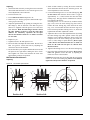
Steam Piping to Coils in the Heat Section
Steam coils are provided without valves for field piping, or
piped with two-way valves and actuator motors.
With the factory piping and valve package, the two coil supplies are piped in parallel and controlled through a single
two-way valve. The field supply connection is of the same
female NPT size as the valve. Field return connections are
made at the 2.50" male NPT fittings on each of the two
stacked coils.
Note:
Air Flow
The valve actuator spring returns to a stem up position upon power failure. This allows full flow
through the coil.
Figure 30. Two-way valve package
Lower
Coil
S u p p ly
Bypass
Supply
R e tu rn
Steam Piping (All Units)
The steam heat section consists of two stacked coils (pitched
at 1/811 per foot [3mm per 30cm]), as shown in Figure 29.
When no factory piping or valve is included, the coil connections are 2.50" male NPT iron pipe.
Piping Recommendations (Steam Coils)
1. Be certain that adequate piping flexibility is provided.
Stresses resulting from expansion of closely coupled piping and coil arrangement can cause serious damage.
Refer to the sections on steam coil piping and trap recommendations for additional information.
2. Do not reduce pipe size at the coil return connection.
Carry return connection size through the dirt pocket, making the reduction at the branch leading to the trap.
Figure 29. Steam Heat Section
(Shown With Factory Valve and Piping)
Upper
Coil
2.12 " ODM
Copper Coil
Connections
3. Install vacuum breakers on all applications to prevent
retaining condensate in the coil. Generally, the vacuum
breaker is to be connected between the coil inlet and the
return main. However, if the system has a flooded return
main, open the vacuum breaker to the atmosphere and the
trap design to allow venting of the large quantities of air.
4. Do not drain steam mains or take-offs through coils.
Drain mains ahead of coils through a steam trap to the
return line.
5. Do not attempt to lift condensate when using modulating
or on-off control.
Return
Lower
Coil
Supply
Return
IM-487
6. Pitch all supply and return steam piping down a minimum
of 1 inch per 10 feet (3mm per 305cm) in direction of flow.
Steam Trap Recommendations
1. Size traps in accordance with manufacturers' recommendations. Be certain that the required pressure differential
will always be available. Do not undersize.
Page 29
2. Float and thermostatic or bucket traps are recommended
for low pressure steam. Use bucket traps on systems with
on-off control only.
3. Locate traps at least 12 inches (305 mm) below the coil
return connection.
4. Always install strainers as close as possible to the inlet
side of the trap.
5. A single trap may generally be used for coils piped in parallel, but an individual trap for each coil is preferred.
Figure 31. Heating Coil Piping With Vestibule
4. If the unit is to be operated in environments with possible
freezing temperatures, an optional freezestat is recommended. Refer to "Freeze Protection" in the "Unit
Options" section of this manual.
Chilled Water Piping
Chilled water coils are provided without valves for field piping, or piped with three-way valves with motor actuators.
Table 8 provides information on units with factory installed
piping and valve packages. The table also provides field
sweat connection information for units not furnished with
factory installed piping and valve packages.
With the factory piping and valve package, the coil assembly
is controlled through a single three-way valve. When two
coils are included in the assembly, they are piped in parallel.
Field connections are male NPT, sized as shown in Table 8.
Refer to Figure 32 for a typical cooling coil with factory
valve and piping.
Figure 32. Chilled Water Coil
(Shown With Factory Valve and Piping)
Air Flow
Return
Freeze Conditions Steam Coils
Entering air temperature below 35°F (2°C)
1. 5 PSI (34.5 kPa) steam must be supplied to coils at all
times.
Bypass
Supply
2. Modulating valves are not recommended. Use face and
bypass dampers.
3. As additional protection against freeze-up, install the trap
sufficiently far below the coil to provide an adequate
hydrostatic head to remove condensate during an interruption on the steam pressure. Estimate 3 feet (914mm) for
each 1 PSI (6.9 kPa) of trap differential required.
Page 30
IM-487
Table 10: Piping Connection Sizes / Valve Size Options For Chilled Water Piping
Cabinet
Size
Application Code
Coil Size
Face Area
H x 83"
Sq. Ft.
(2108 mm)
(Sq. m)
Long
Blow-thru or Draw-thru
Small Coil Section
33 + 33
(2 coils)
(838 +
838 mm)
38.0
(3.53 m²)
Blow-thru or Draw-thru
Large Coil Section
39 + 39
(2 coils)
(991 +
991 mm)
45.0
(4.18 m²)
Face and Bypass
Section With Small Coil
48
(1219 mm)
27.7
(2.57 m²)
Face and Bypass
Section With Large Coil
39 + 39
(2 coils)
(991 +
991 mm)
45.0
(4.18 m²)
Blow-thru or Draw-thru
Small Coil Section
45 + 45
(2 coils)
(1143 +
1143 mm)
51.9
(4.82 m²)
Blow-thru or Draw-thru
Large Coil Section
63 + 63
(2 coils)
(1600 +
1600 mm)
72.6
(6.74 m²)
Face and Bypass
Section With Small Coil
63
(1600 mm)
36.3
(3.37 m²)
Face and Bypass
Section With Large Coil
54 + 54
(2 coils)
(1372 +
1372 mm)
62.3
(5.74 m²)
Blow-thru or Draw-thru
Cooling Only Coil
Section
48 + 78
(1220 +
1981 mm)
26.0
(2.42 m²)
Blow-thru or Draw-thru
Unit Coil Section
48 + 78
(1220 +
1981 mm)
26.0
(2.42 m²)
Face and Bypass
Section With Small Coil
30 + 79
(763 +
2006 mm)
16.5
(2.57 m²)
Blow-thru or Draw-thru
Contractor Coil Section
36 + 79
(915 +
2006 mm)
19.8
(4.18 m²)
047C
077C
800
or
802
5WH
Available
Rows **
3
4
5
6
8
3
4
5
6
8
3
4
5
6
8
3
4
5
6
8
3
4
5
6
8
3
4
5
6
8
3
4
5
6
8
3
4
5
6
8
3
4
5
6
3
4
5
6
3
4
5
6
8
10
3
4
5
6
8
10
Available Circuiting
5WS
5WL
5WM
5WD
Columns*
1
2
1
2
1
2
1
2
1
2
D
D
D
D
D
D
D
D
D
D
F
F
F
F
F
D
D
D
D
D
C
C
C
C
C
B
B
B
B
B
E
E
E
E
E
C
C
C
C
C
G
G
G
G
G
G
G
G
—
—
—
—
—
—
—
—
—
—
—
—
R
R
R
R
R
R
R
R
R
R
U
U
U
U
U
R
R
R
R
R
R
R
R
R
R
Q
Q
Q
Q
Q
T
T
T
T
T
R
R
R
R
R
T
T
T
T
T
T
T
T
L
L
L
L
L
L
L
L
L
L
L
L
D
D
D
D
D
C
C
C
C
C
E
E
E
E
E
C
C
C
C
C
C
C
C
C
C
B
B
B
B
B
C
C
C
C
C
C
C
C
C
C
G
G
G
G
G
G
G
G
—
—
—
—
—
—
—
—
—
—
—
—
Q
Q
Q
Q
Q
Q
Q
Q
Q
Q
T
T
T
T
T
Q
Q
Q
Q
Q
Q
Q
Q
Q
Q
P
P
P
P
P
S
S
S
S
S
Q
Q
Q
Q
Q
T
T
T
T
T
T
T
T
M
M
M
M
M
M
M
M
M
M
M
M
—
B
—
B
B
—
C
—
C
C
—
C
—
C
C
—
C
—
C
C
—
C
—
C
C
—
B
—
B
B
—
C
—
C
C
—
B
—
B
B
—
G
—
G
—
G
—
G
—
—
—
—
—
—
—
—
—
—
—
—
—
Q
—
Q
Q
—
Q
—
Q
Q
—
S
—
S
S
—
Q
—
Q
Q
—
P
—
P
P
—
P
—
P
P
—
S
—
S
S
—
P
—
P
P
—
T
—
T
—
T
—
T
—
M
—
M
M
—
K
—
K
K
K
K
A
B
B
B
B
A
C
C
C
C
A
C
C
C
C
A
C
C
C
C
A
B
B
B
B
A
B
B
B
B
A
C
C
C
C
A
B
B
B
B
—
—
—
—
—
—
—
—
—
—
—
—
—
—
—
—
—
—
—
—
Q
Q
Q
Q
Q
Q
Q
Q
Q
Q
S
S
S
S
S
Q
Q
Q
Q
Q
P
P
P
P
P
P
P
P
P
P
S
S
S
S
S
P
P
P
P
P
—
—
—
—
—
—
—
—
N
N
N
N
N
N
N
N
N
N
N
N
A
B
A
A
B
A
B
A
A
B
A
C
A
A
C
A
B
A
A
B
A
B
A
A
B
A
B
A
A
B
A
C
A
A
C
A
B
A
A
B
—
—
—
—
—
—
—
—
—
—
—
—
—
—
—
—
—
—
—
—
P
P
P
P
P
P
P
P
P
P
S
S
S
S
S
P
P
P
P
P
P
P
P
P
P
P
P
P
P
P
S
S
S
S
S
P
P
P
P
P
—
—
—
—
—
—
—
—
N
N
N
N
N
N
N
N
N
N
N
N
** Available with 8, 10 or 12 fins per inch.
* Columns 1 and 2 are explained on page 32.
IM-487
Page 31
Table 10 Available Circuiting Legend
Column 1:
These units are available with a factory installed package consisting of a three-way water valve and connecting piping.
A = This combination is not available with a factory installed piping and valve package.
B = 300, 2.50, or 200 inch three-way valves can be specified
C = 300, 2.50, 2.00, or 150 inch three-way valves can be specified
D = 250, 200, or 150 inch three-way valves can be specified
E = 250, 200, 150, or 1.25 inch three-way valves can be specified
F = 200, 1.50, or 125 inch three-way vales can be specified
G = 1.25, 1.50, 2.00 or 2.50 inch three-way valves can be specified
Field supply and return female NPT connection sizes are the same as the valve size.
Column 2:
The following letters designate units that are not furnished with the factory installed piping/valve package. Required are field
sweat connections, at one or two coils, to male copper tubing for the supply and return water piping.
K = A single 2.00 inch NPT supply and return if fin height is 21 - 30 inches and 2.50 inches of fin height is 30 - 36 inches.
L = A single 1.50 inch NPT supply and return
M = A single 2.00 inch NPT supply and return if fin height is 21 - 30 inches
N = A single 2.50 inch NPT supply and return
P = Two 3.12 inch O.D. supply and two 3.12 O.D. return connections
Q = Two 2.62 inch O.D supply and two 2.62 O.D. return connections
R = Two 2.12 inch O.D. supply and two 2.12 O.D. return connections
S = One 3.12 inch O.D supply and one 3.12 O.D. return connections
T = One 2.62 inch O.D supply and one 2.62 O.D. return connections
U = One 2.12 inch O.D supply and one 2.12 O.D. return connections
Page 32
IM-487
Vestibule Assembly Instructions
An accessory vestibule is available to provide additional piping space for coils installed in a four-foot section. A vestibule
is required to maintain door access on a combination heating
and cooling section. Assemble the vestibule to the unit part
by part as shown in Figure 33.
Note:
Step 2
Remove gasketing around door flange and save for use on
vestibule. See Step 4. Remove door and save for Step 4.
Figure 34. Step 2 Illustration
The door, hinge, and latch assemblies from the unit
are used on the vestibule.
Step 1
Remove door from section where vestibule is to be located
by removing screws holding hinges to upright support (leave
hinges on door). Set door aside and save for Step 4.
Remove door latch assembly from other side upright support.
Use offset Phillips screwdriver or a wrench to remove screws
holding latch assembly in place. Save door latch assembly,
screws and bushings for Step 4.
Figure 33. Step 1 Illustration
Gasketing
Door Prop
Door
Door Latch Assembly
IM-487
Page 33
Step 3
1. Assemble side panels A and B to uprights using #10 drill
screws supplied. Make certain side panels are flush
against uprights before securing into place.
2. Fasten bottom panel D to base channel using #10 drill screws
and to side panels A and B using #10 screws supplied.
Step 4
1. Reassemble access door to vestibule by screwing hinges
into side panel using screws saved from Step 1. (Access
door must be attached to the vestibule in the same opening
direction as it was on the unit.)
3. Set top panel C in place and fasten to side panels A and B
using #10 screws and to top panel using #10 screws supplied.
2. Remove and discard latch handle locking screws and
retaining washer. Fasten door latch assembly to side panel
using screws and bushings saved from Step 1. (Latch must
be fastened on the same side as when located on the unit.)
Figure 35. Step 3 Illustration
3. Fasten upright angles to vestibule using #10 screws supplied.
#10 Screw
4. Seal between unit and vestibule with silicone sealant along
top and sides as shown.
Note:
Any holes cut in the floor of the unit must be sealed
to prevent water leakage.
Figure 36. Step 4 Illustration
Silicone
Sealant
Gasketing
Upright Angle
#10 Drill
Screw
#10 Screw
Silicone
Sealant
Door
Prop
#10 Screw
Door
Page 34
Gasketing
Upright
Angle
Door Latch Assembly
(See Note)
IM-487
Damper Assemblies
The optional damper assemblies described in this section are
provided with manually adjustable linkages, or may be
shipped with factory installed actuators and linkages in units
that include factory controls.
Economizer Dampers
Outside air intake is provided on both sides of the unit, and
the return air path is at the center of the damper set. As the
single actuator modulates the outside air dampers open, the
return air dampers close. Exhaust air exits the unit through
the gravity relief dampers provided at the end of the economizer section.
The outside air return air damper assembly (economizer)
comes with manually adjustable linkage. This adjustable
linkage can also be used for connection of a damper operator.
The damper is set so that the crankarm moves through a 90degree angle to bring the economizer dampers from full open
to full close. Mechanical stops have been placed in the crankarm mounting bracket. Do not remove stops. If crankarm is
driven past stops, damage to linkage or damper will result.
The unit will ship with a shipping bolt securing the linkage
crankarm. Remove shipping bolt before use.
Figure 37. Economizer Dampers
Outside
Air
Optional Return Air Fan
Economizer
Outside
Air
Shaft .500 Dia.
x 1.50 Long
90∞
OA
Stroke
Open
OA
Closed
.25
3.00
OA
Closed
90∞
Stroke
OA
Open
.25" (6mm)
.500 (13mm) Dia. Shaft
x 1.30" (33mm) Long
.75
RDS 800C & 802C
Note:
IM-487
RAH 047C - 077C
For good airflow control, adjust linkages so damper blades do not open beyond 70 degrees. Opening a damper blade
beyond 70 degrees has little effect on its airflow. Do not "overclose " low leak damper blades. The edge seal should just
lightly contact the adjoining blade. The blades will lock-up if they are closed so far that the seal goes over center.
Page 35
Intake Hood Damper
Intake Hood Damper
(0 to 100% Outside Air, RAH 47-77 Only)
(0 to 30% Outside Air)
Units requiring 100% outside air are provided with a rain hood
and dampers which may be controlled by a single actuator. The
actuator, which may be ordered with factory controls, provides
two position control for opening the dampers fully during unit
operation and closing the dampers during the off cycle. No unit
mounted exhaust dampers are provided.
These dampers are intended to remain at a fixed position during unit operation, providing fresh air quantities from 0 to
30% of the total system airflow, depending on the damper
setting. This setting is made at the linkage rod on units with
manually adjustable linkages.
Figure 38. Intake Hood Damper - 0-100% Outside Air
On units provided with MicroTech™ controls, the damper
position may be set at the controller keypad. During unit
operation, the two-position actuator drives the damper to the
position set on the keypad. During the off cycle, the damper
is automatically closed.
No unit mounted exhaust dampers are provided with this
option.
AIRFLOW
Figure 39. Intake Hood Damper - 0-30% Outside Air
ow
rfl
Ai
3.15" (80 mm)
Max. Stroke of
Damper Linkage Bar
Note:
90∞
Stroke
OA
Closed
OA
Open
.25" (6mm)
Page 36
1. Figure 39 shows the RAH 47-77 (The linkage is
on the RH side).
2. The RDS 800-802 are the same except the linkage is on the LH side.
IM-487
Mixing Box (RAH 47-77 only)
This section utilizes an outside air damper and a return air
damper. Use of these dampers allows outside air to be
blended with return air. Synchronized operation of the
dampers is accomplished by interconnecting rods. As one
damper section opens, the other section is being closed.
Always a total of 100% CFM is drawn from this section.
Damper positioning may be either manually or automati-
cally adjusted. With a field installed controller, automatic
operation can be obtained.
These dampers provide a similar function to the economizer
dampers. This option differs from an economizer in that no
unit mounted exhaust dampers are provided.
Figure 40. Mixing Box
90∞
STROKE
OA
OPEN
OA
CLOSED
.25" (6 mm)
OA
CLOSED
.75"
(19 mm)
OA
OPEN
Note:
IM-487
3.00"
(76 mm)
For good airflow control, adjust linkages so damper blades do not open beyond 70 degrees. Opening a damper blade
beyond 70 degrees has little effect on its airflow. Do not "overclose " low leak damper blades. The edge seal should just
lightly contact the adjoining blade. The blades will lock-up if they are closed so far that the seal goes over center.
Page 37
Face and Bypass Dampers
Face and bypass dampers are available in a flat arrangement
for use with heating coils and standard face area cooling
coils, as well as a staggered arrangement for large face area
cooling coils. The damper sets are linked through a jack shaft
for connection to a single actuator (factory or field installed).
Figure 41. Face and Bypass Dampers - RDS 800-802 only
Airflow
Face Dampers
Open
Face and
Bypass
Damper
.75"
(19mm)
90∞
Stroke
3.00"
(76mm)
Face Dampers
Closed
Figure 42. Face and Bypass Dampers - Staggered Arrangement - RAH 47-77 only
Face Damper
Open
90∞
Stroke
.25"
(6mm)
Closed
.75"
(19mm)
3.00"
(76mm)
Airflow
Bypass Damper
Page 38
IM-487
Figure 43. Face and Bypass Dampers - Flat Arrangement - RAH 47-77 only
Optional
Contractor
Coil
Face and Bypass
Damper
Extended
Shaft
Face and Bypass
Dampers
Cabinet Weatherproofing
This unit ships from the factory with fully gasketed access
doors and cabinet caulking to provide weatherproof operation. After the unit has been set in place, inspect all door gaskets for shipping damage and replace if necessary.
IM-487
It is recommended the unit be protected from overhead water
run-off from overhangs or other structures. Re-caulk field
assembled options, such as external piping vestibules or split
units, per installation instructions provided with the option.
Page 39
Electrical Installation
Field Power Wiring
Without Optional Electrical Power Package
All of the unit side panels are hinged. Disconnect switches
and/or motor starters must not be mounted on panels which
provide access to internal components. Wiring conduits can
penetrate the cabinet bottom, base frame or through the hinge
and latch cap without interfering with the access panels.
Note:
All holes cut into the unit must be sealed to prevent
water leakage.
Conduits connecting the unit to external panels will be
exposed to relative humidity and air pressure differentials
and should be sealed. Ground the motor using copper or
other corrosion resistant conductor.
Figure 44. Field Power Wiring
Access
Panels
With Optional Electrical Power Package
Wiring must comply with all applicable codes and ordinances. The warranty is voided if wiring is not in accordance
with these specifications.
According to the National Electrical Code, a disconnecting
means shall be located within sight of and readily accessible
from the air conditioning equipment. The unit may be
ordered with an optional factory mounted disconnect switch.
This switch is not fused. Power leads must be overcurrent
protected at the point of distribution. The maximum allowable overcurrent protection is shown on the unit nameplate.
The RAH units may be ordered with internal power wiring
for either single or multiple point power connections. If single point power is ordered, a single power block or an
optional disconnect switch is located within the main control
panel. Field power leads are brought into the unit through 3inch knockouts in the bottom of the main control panel. Refer
to Figure 45.
Units ordered with dual point power connections are provided with non-fused, factory mounted disconnect switches.
Disconnect DS1 handles the fan load and controls, and is
mounted within the main control panel. Disconnect DS3 handles the electrical heat load and is located within the electric
heat control panel.
Hinge and
Latch Cap
Top
DANGER
Hazardous voltage.
May cause severe injury or death.
Bottom
Must Seal
Access
Panel
Lock and tag out all electric power before servicing
equipment. More than one disconnect may be required
to de-energize the unit.
If the unit has a factory mounted disconnect switch, the
switch must generally be turned off to open the main
control panel door.
The door can be opened without disconnecting power
by turning the screw at the bottom of disconnect switch
clockwise while pulling the door open. If this is done,
however, caution must be used since power is not
removed from the unit or the controller.
The minimum circuit ampacity (wire sizing amps) is shown
on the unit nameplate. Refer to Table 11 for recommended
number of power wires.
Base
Frame
Bottom
Page 40
IM-487
Table 11: Recommended 3-phase power wiring*
FOR MCA
Up to
(Amps)
Wire
Gauge
Qty./
Pole
Insulation
rating (°C)
No. of
Conduits
Conduit/
(Trade,
Size, In.)
30
10
1
60
1
1/2
40
8
1
60
1
3/4
55
6
1
60
1
1
70
4
1
60
1
1-1/4
85
3
1
60
1
1-1/4
95
2
1
60
1
1-1/4
130
1
1
75
1
1-1/4
150
1/0
1
75
1
1-1/2
175
2/0
1
75
1
2
200
3/0
1
75
1
2
230
4/0
1
75
1
2
255
250
1
75
1
2-1/2
285
300
1
75
1
2-1/2
310
350
1
75
1
3
335
400
1
75
1
3
380
500
1
75
1
3
400
3/0
2
75
2
2
460
4/0
2
75
2
2
510
250
2
75
2
2-1/2
570
300
2
75
2
2-1/2
620
350
2
75
2
3
670
400
2
75
2
3
760
500
2
75
2
3
765
250
3
75
3
2-1/2
855
300
3
75
3
2-1/2
930
350
3
75
3
3
A ground lug is provided in the control panel for each power
conduit. Size grounding conductor in accordance with Table
250-95 of the National Electrical Code.
In compliance with the National Electrical Code, an electriCally isolated 115V circuit is provided in the unit to supply
the factory mounted service receptacle outlet and optional
unit lights. This circuit is powered by a field connected 15A
115V power supply. Leads are brought into the RAH unit
through a 7/8" knockout in the bottom of the main control
panel, near the power wire entry point.
WARNING
Electrical shock hazard.
May cause severe injury or death.
All protective deadfront panels must be reinstalled and
secured when power wiring is complete.
Figure 45. Power Wiring Entrance
Electric Heat
Control Panel
NOTE: Refer to Certified
Drawings for dimensions
to wire entry points.
Disconnect
Switch DS3
(Optional)
Main
Control
Panel
*To provide that disconnects and power blocks mate with power wiring
Notes:
1. All wire sizes assume separate conduit for each set of
parallel conductors.
2. All wire sizes based on NEC Table 310-16 for THW wire (copper).
Canadian electrical code wire ampacities may vary.
3. All wire sizes assume no voltage drop for short power leads.
*To provide that disconnects and power blocks mate with power wiring.
Copper wire is required for all power lead terminations at the
unit. Size wires in accordance with the ampacity tables in
Article 310 of the National Electrical Code. If long wires are
required, it may be necessary to increase the wire size to prevent excessive voltage drop. Size wires for a maximum of
3% voltage drop. Supply voltage must not vary by more than
10% of nameplate. Phase voltage imbalance must not exceed
2%. (Calculate the average voltage of the three legs. The leg
with voltage deviating the farthest from the average value
must not be more than 2% away.) Contact local power company for correction of improper voltage or phase imbalance.
Terminal Block
TB1 for 115V
Service
Receptacle
Circuit
Power Block PB: or
Disconnect Switch DS1
3" Knockouts for Power Wire
(Qty. 3 in Main Control Panel;
Qty. 3 in Electric Heat Control Panel)
7/8" Knockouts for 115V
Service Receptacle Circuit
Figure 46. Optional Side Power Wiring Entrance
2.75"
(70mm)
3" (76mm) Max. Dia.
CAUTION
Improper line voltage or excessive phase
imbalance constItutes product abuse. May cause
severe damage to the unit electrical components.
Main
Control
Box
Assure proper line voltage and phase balance.
Remove Lifting
Bracket Before
Drilling Hole
IM-487
16.00"
(406mm)
Page 41
The preferred entrance for power cables is through the bottom knockouts provided on the unit. If side entrance is the
only option, a drilling location is provided. The drilling
dimensions must be followed exactly to prevent damage to
the control panel. The dimensions provided are the only possible point of side entrance for the power cables.
Field Control Wiring
CAUTION
Wiring must comply with applicable codes and
ordinances and these specifications.
Defects caused by incorrect wiring are not covered by the
warranty.
Connect the control wiring as shown on the wiring diagrams
provided with the unit. Units are available with a number of
optional control arrangements. Specific field wiring connections for these arrangements are described in IM-696 and OM
137 or OM 138.
If unit mounted control devices are to be installed in the field,
control wiring may be run from the device to the main control box using the control wiring raceway shown in
Figure 47. Connect field wired harnesses to terminal blocks
TB2. TB5. TB7, TB8 or TB10 as indicated on the unit schematics. The field control wiring terminal block TB2 is
located in the main control panel. Refer to Figure 47.
Two 7/8" knockouts are provided for wire entry.
WARNING
Electrical shock hazard.
Can cause severe injury or death.
Connect terminal strip TS2 to 24V Class II circuits only.
Do not connect these contacts to a field supplied 115V
power source.
Reinstall and secure all protective deadfront panels when
the wiring installation is complete.
Interconnecting wiring between the rooftop air handler unit
and a remote condensing unit or chiller enters the rooftop air
handler unit through 7/8" knockouts in the bottom of the
main control panel. The 115V wiring is connected to TB5.
Page 42
Refer to “Typical Control Circuit with Power Pack Only” on
page 50. The TBS output relays must switch "AC" loads. The
load voltage rating must be within the range 24 to 140 VAC.
The maximum load current is 1.8A and the minimum load
current is 30mA. The 24V wiring is connected to terminal
block TB7 which is illustrated in “Typical Main Control Circuit (VAV Units)” on page 52.
A 7/8" knockout is also available in the end of the unit base
as shown in Figure 48. Note: If a single conduit containing
24V and 115V wiring is run above the roofline, the 24V wiring must be installed as an NEC Class I wiring system.
Figure 47. RAH Field Control Wiring Connections
M a in C o n tr o l
P a n e l
2 4 V
T e rm
B lo c
(T B 2
k
F ie ld
in a l
)
C o
C o
to
b o
c o
n tr o l W ir in g R
v e r (R e m o v e
h a rn e s s fro m
x to u n it m o u n
n tr o l d e v ic e s )
a c e w a y
fo r a c c e s s
m a in c o n tr o l
te d
Figure 48. RAH Interconnecting Control Wiring
M a in
C o n tro l
P a n e l
T B 7
(2 4 V )
R F S U n it
R C S U n it
T B 3
(1 1 5 V )
T B 5
(1 1 5 V )
C o n d e n s e r
C o n tr o l P a n e ls
T B 2
(2 4 V )
IM-487
Preparing Unit for Operation
Figure 49. Supply Fan Assembly
WARNING
Moving machinery hazard.
Can cause severe injury or death.
H o ld - d o w n
F a s te n e rs
Lock out and tag out all power and lock off before servicing equipment. More than one disconnect may be
required to de-energize unit.
Relief Damper Tie-Down
(RDS 800-802 units only)
Economizer sections with a 30" or 40" return fan have a
relief damper that is tied down for shipping. Two brackets
and two screws must be removed before operation to allow
free movement of dampers. Access is from inside the economizer section.
Spring Isolated Fans
H o ld - d o w n
F a s te n e rs
Release of Spring Mounts
Spring-mounted supply and return fans are locked down
for shipment.
Figure 50 shows a typical spring mount. Note that the 3/8"
hold-down bolt securing the fan base to the unit cross channel must be removed, as well as all 1/4"screws directly above
the spring mount.
Return Fans
Hold-down fasteners are located at each spring mount. These
fasteners must be removed before operating the fans.
In some unit arrangements, one of the 3/8" hold-down bolts
lies below the motor base. The bolt can be reached with a
9/16" socket and must be removed.
The front mounts on RDS 800-802 return fans are accessible
by removing a 3" OD closure plug in the louvered fresh air
intake. Replace the plug after removing the lock-down bolts.
After removing the hold-down fasteners, rock by hand the
fan assembly to check for freedom of movement.
If it is necessary to change or replace the forward (front) isolators on the RDS 800 or 802 return fan, proceed as follows:
1. Open fresh air intake louver door and remove the triangular shaped floor pan (remove sheet metal screws).
2. Forward spring mount is now visible and can be replaced.
Figure 50. Spring Mounted Hold-Down Fasteners - All Units
3 /8 " H o ld - d o w n B o lt
(M a y b e s e c u re d to
e ith e r fla n g e o n
c r o s s c h a n n e l) ;
R e m o v e B e fo re
R u n n in g F a n
1 /4 " H o ld - d o w n S c r e w ;
R e m o v e B e fo re
R u n n in g F a n
3. Caulk all edges of the floor pan before reinstalling to prevent leaks.
Supply Fans
Hold-down fasteners are located at each of the two spring
mounts on the inlet side of the fan base. A third hold down
fastener is located on the fan base directly below the bearing
on the wheel side of the fan assembly. Refer to Figure 49.
IM-487
Page 43
Adjustment of Supply Fan Thrust Restraints
Thrust restraints are provided when housed double-width fans
are mounted on springs. After the spring mounts have been
adjusted for level operation when the fan is running, check the
thrust restraints. With the fan off, set the adjustment nuts so
the spring is slightly compressed against the angle bolted to
the fan housing frame. When the fan is turned on, the fan will
move back to a level position and the thrust restraint springs
will compress. Refer to Figure 51 on page 44.
1. With the fan off, loosen Jam Nuts "A".
2. Turn Nut "C" until the spring cup and washer contact
thrust restraint angle.
3. Turn Nut "B" until spring is compressed by two turns of
Nut "B".
Adjustment of Spring Mounts
During operation, all fans should ride level, with the bottom
of the fan base approximately 3/8" (10mm) above the top of
the unit's cross channel. Unhoused single-width "plug" fans
will also ride at this level when at rest.
When not operating, housed double-width fans will ride
lower at the discharge end of the fan base than at the motor
end. When the fan is operating against a static pressure, it
should run level. If not, level the assembly as follows:
(refer to Figure 52)
1. Loosen the 15/16" jam nut above the fan base.
4. Tighten Jam Nuts "A".
2. Using a large, straight blade screwdriver, turn the 5/8"
leveling screw clockwise to lower the fan base, counterclockwise to raise the fan base.
Figure 51. Thrust Restraint Adjustment
3. When properly adjusted, retighten the jam nut.
.
J a m
N u t "A "
DANGER
N u t "B "
S p r in g C lip
F a n B u lk h e a d
Moving machinery hazard.
Can cause severe injury or death.
W a s h e r
N u t "C "
Lock out and tag out all power before working on the fans.
Figure 52. Fan Spring Mount Adjustment
J a m
N u t "A "
T h r u s t R e s tr a in t A n g le
F a n H o u s in g F r a m e
D e ta il " A "
L e v e lin g
S c re w
J a m
N u t
F a n
B a s e
S p r in g
M o u n t
A s s e m b ly
C ro s s
C h a n n e l
3 /8 "
(1 0 m m
W IT
R U N
± 1 /4
± 6 m
H F A
N IN G
N
"
m )
!*
* This (10mm) can be affected by thrust restraints that are grossly out of
adjustment. This dimension must be rechecked after thrust restraints are
adjusted.
S e e D e ta il " A "
Adjustment of Seismic Restraints
Spring mounted supply air and return air fans may be ordered
with factory installed seismic restraints. The system consists
of four snubbers, one located next to each spring isolator.
These snubbers will allow free movement of the fan assemblies during normal operation because normal operation will
not cause fan movements that exceed .25" (6 mm). However,
they will restrain the fan assembly and limit movement to
.25" (6 mm) in any direction if an abnormal condition were
to occur.
The position the fan will assume during normal operation
will be determined by actual job site airflow and static pressure. Therefore, for proper operation, the seismic restraints
must be field adjusted as part of the normal "Check, Test and
Start" procedure. When the fan is operating in a normal manner there should be no contact between the snubber restrainer
Page 44
IM-487
angle and the snubber neoprene bumper. However, in a "seismic event," the snubber will limit movement of the spring
mounted fan assembly to .25" (6 mm) in any direction,
thereby helping to prevent the fan from being tossed about
and damaged, or causing damage.
The seismic restraint is adjustable in all directions. Vertical
slots in the restrainer angle and horizontal slots in the blower
base allow the restrainer angle to be adjusted up and down
and back and forth. The neoprene center bumper is mounted
on a slotted hole allowing its adjustment in and out.
When a seismic restraint is properly adjusted and the fan is
operating normally, the neoprene center bumper will be centered within the 2" (51 mm) diameter hole in the restrainer
angle, and the restrainer angle will be centered vertically
between the flanges of the neoprene center bumper. This
results in .25" (6 mm) clearance in all directions. When the
fan is turned off the restrainer angle may come to rest on the
neoprene center bumper.
Removing the neoprene center bumper bolt allows removal,
disassembly, and replacement of the neoprene components.
Figure 53. Cross Section of Seismic Restraint
F a n B a s e C h a n n e l
Adjustment of Scroll Dampers
(RDS 800 Only)
Two sets of scroll dampers are provided in the housing of the
twin 15" x 6" supply fan to allow control of air volume to
each fan wheel. At the factory, these dampers are fully closed
unrestricting airflow. If fan paralleling occurs, correction can
be made by loosening the adjustment screws on top of the fan
housing and slightly lowering the rod until air distribution
between the fans is even. See Figure 54.
S n u b b e r R e s tr a in e r A n g le
Figure 54. Scroll Damper Adjustment
A d ju s t U p o r D o w n
o r B a c k a n d F o rth
A d ju s tm e n t A s s e m b ly
S n u b b e r N e o p re n e
B u m b e r
.2 5 " (6 m m ) G a p
( F a n R u n n in g )
S c r o ll D a m p e r
S n u b b e r N e o p re n e
B u m b e r
A d ju s t In a n d O u t
IM-487
Page 45
Sequences of Operation
The following sequences of operation are for a typical "C" vintage applied rooftop unit that is equipped with MicroTech II,
an economizer, 4 compressor / 8 stage cooling, 3 to 1 turn
down burner, variable frequency drives (VFD), a return air fan
and an external time clock. These sequences describe the ladder wiring diagram logic in detail; refer to “Wiring Diagrams”
on page 48 as you read them. Note that your unit's sequences
of operation may vary from those described here. Refer to the
wiring diagrams supplied with the unit for exact information.
For detailed description of operation information relating to
the MicroTech II controller's software, refer to the appropriate operation manual (see Table 1 on page 3). These manuals
describe the various setpoints, parameters, operating states,
and control algorithms that affect rooftop unit operation.
Power-up
When primary power is connected to the unit, 115VAC power
is fed through control circuit transformer TI and control circuit fuse FI (line 200) to compressor crankcase heaters HTR-1,
HTR-2, HTR-3 and HTR-4 (lines 825, 875, 823 and 873).
When system switch S1 (line 205) is closed, low voltage transformers T2 (line 205), T3 (line 300)and T9 (line 805) are energized, and 115VAC power is supplied to the following:
•
•
•
•
•
•
•
•
Smoke detectors (line 284)
Economizer actuator ACT3 (line 336)
Supply fan vane actuator ACT1 (line 340) or
M30A to energize the supply fan VFD (line 311)
Return fan vane actuator ACT2 (line 346) or
M40A to energize the return fan VFD (line 316)
Heating control panel
Compressor circuit switches CSI and CS2 (lines 828 and 878)
Transformer T2 supplies 24VAC power to terminals 24V &
24C on the main control board MCB (lines 207 and 208). By
way of terminal TB6-48 (lines 206), transformer T2 supplies
24VAC power to the following:
•
•
•
•
•
•
•
•
•
•
Switch S7 On-Auto-Off (line 223)
Enthalpy sensor OAE (line 265)
External time clock contacts (line 222)
External exhaust fan status contacts (line 273, VAV only)
Airflow interlock switch PC7 (line 248)
Dirty filter switches PC5 and PC6 (lines 256 and 260)
Duct high limit switch DHL (line 276, DTC only)
Gas furnace alarm relay R24 (line 244)
Freezestat switch FS1 (line 251, hot water or steam heat only)
Smoke detectors SDI and SD2 (line 254)
When the field supplied Cool Enable switch is in the "off"
position, field wiring terminal 105 is de-energized (line 233).
Binary input MCB-BI3 will be de-energized and the cooling
will be disabled. When the field supplied Heat Enable switch
is in the "off" position, field wiring terminal 106 is de-energized (line 242). Binary input MCB-BI4 will be de-energized and the heating will be disabled. Note: Unit ships with
factory installed jumpers between 101 and 105 and between
101 and 106.
Page 46
Fan Operation
When the supply and return fans are commanded to start by
the Microprocessor Control Board (MCB), the unit enters the
Startup Initial operating state. As a result, a 3-minute timer is
set, output MCB-BO3 (line 394) energizes and relay R26 energizes (line 393). On VAV units with inlet vanes, outputs MCBBO14 and MCB-BO16 energize (lines 344, 342), causing the
supply and return fan inlet vanes to open. When the vanes
open to their minimum positions, MCB-BO14 and MCBBO16 are de-energized, causing the inlet vanes to hold.
After the 3-minute timer expires, the unit enters the Recirculate operating state. As a result, output MCB-BO1 energizes
relay R67 (line 304). This gives a start signal to supply fan
drive AFD10 (line 343). Four seconds after MCB-BO1 is
energized, output MCB-BO2 energizes relay R68 (line 305).
This gives a start signal to return fan drive AFD20 (line 343).
Overload relays OL9, OL10, OL19, and OL20 (line 311) protect the fans from excessive current draw. If either the supply
or return fan is drawing excessive current, one of the relays
will open its contacts and cause both fans to stop.
Within 120 seconds after the fans start, the controller expects
airflow switch PC7 (line 248) to close and thus energize
binary input MCB-BI6. (If MCB-BI6 does not energize, the
controller will assume the fans did not start. It will then shut
down the unit and generate an alarm.)
During the Recirculate operating state, the outside air damper
is held closed. The controller does this by energizing output
MCB-BO5 (line 338). On VAV units, output MCB-BO12, the
VAV box output, is also de-energized (line 395) during the
Recirculate state.
On VAV units, the supply fan adjustable frequency drive
(AFD10) or inlet vanes (ACT1) are modulated to maintain
the duct static pressure setpoint. When energized, output
MCB-BO14 drives AFD10/ACT1 towards increased capacity, and MCB-BO13 drives them towards decreased capacity
(line 344). On VAV units or CAV units equipped with return
fan capacity control, the adjustable frequency drive (AFD20)
or the return fan vanes (ACT2) are modulated to maintain an
acceptable building static pressure (using either VaneTrol
logic or direct measurement of building pressure: see the
appropriate OM for more information). When energized,
output MCB-BO16 drives AFD20/ACT2 towards increased
capacity, and MCB-BO15 drives them towards decreased
capacity (line 342).
Economizer Operation
When the outdoor air is suitable for free cooling, the switch
in enthalpy sensor OAE is in position "3" (line 267) energizing binary input MCB-BI11. When MCB-BI11is energized,
the economizer is enabled. (Note: If selected from the keypad, the enthalpy decision can be made based on outdoor
temperature. In that condition, if the outdoor air temperature
is less than or equal to the changeover setpoint, the economizer is enabled.) If cooling is required, the economizer
dampers (ACT3) are modulated to maintain the discharge air
temperature setpoint. When energized, output MCB-BO6
IM-487
drives the outdoor air dampers towards the open position,
and MCB-BO5 towards the closed (line 338). If the outdoor
air dampers are wide open and more cooling is required, the
dampers will hold their positions and mechanical cooling
will be activated (see below).
When the outdoor air is not suitable for free cooling, the
switch in enthalpy sensor OAE is in position "1", de-energizing binary input MCB-BI11 (Alternatively, the outdoor air
temperature is above the changeover setpoint plus the economizer changeover differential). When the economizer is disabled, the dampers are held at their minimum position.
Heating
Gas Furnace, Modulating Burner (3 to 1 turn down)
Refer to “Typical Gas Furnace Control Circuit (Modulating
Burner, Mixed Air Intake)” on page 58 as you read this
sequence of operation. Note that the gas furnace wiring diagrams supplied with the units include a detailed sequence of
operation. Refer to the wiring diagram supplied with the unit
for exact wiring and sequence of operation information.
When system switch S1 is closed, 115 VAC power is supplied to the furnace control circuit. If burner switch S3 and
safeties HL22, HL23 are closed, terminal 5 (line 615) on the
flame safeguard control (FSG) will be energized as will the
modulating gas valve VM1. If heating is enabled (MCB-BI4
is energized) and heating is required, the MCB-BO11 will
energize (line 605), thus energizing relay R20. The normally
open R20 contacts (line 610) close, and if manual burner
switch S3 and safeties HL22, HL23, FLC (high limit switch),
LP5, and HP5 are closed, terminal 6 (line 631) on the flame
safeguard control (FSG) will be energized. FSG will energize terminal 4 to start the blower motor (BM) through contactor M29 (line 615). If the blower is operational, air switch
AS (line 633) will close and make FSG terminal 6 to 7. After
a 90-second prepurge period, FSG terminals 8 (line 621) and
10 (line 630) are energized. As a result, ignition transformer
IT and pilot gas valve GVI are energized. The pilot flame
will ignite and be detected by FSG through flame rod FD
(line 622). Upon detection of pilot flame after the 10 second
trial for ignition period, the FSG will de-energize terminal 10
and energize terminal 9 to energize main gas valves GV2 and
GV3 (lines 625, 626) and low fire start relay R23 (line 628).
IM-487
The R23 contacts (lines 642 and 643) allow the MCB to
modulate gas valve actuator VM1 as required to satisfy the
heating demand.
Whenever the burner is operating, its firing rate will be determined by the position of gas valve actuator VM1. This actuator modulates the butterfly gas valve and combustion air
damper (lines 690 and 692), thus varying the furnace firing
rate between 33% and 100% of full capacity. When the MCBBO10 energizes (line 645), VM1 modulates toward open and
the firing rate increases. When MCB-BO9 energizes (line
644), VM1 modulates toward closed and the firing rate
decreases. When both MCB-BO10 and MCB-BO9 are open,
VM1 holds its position and the firing rate remains constant.
When heating is no longer necessary, MCB-BO11 opens, deenergizing relay R20 and opening its contacts in line 610. As
a result, the flame safeguard control is de-energized, all gas
valves close, the combustion air blower motor stops, and gas
valve actuator VM1 closes. If the furnace is warm enough to
close it, the FLC fan controls switch (line 609) will override
supply fan start/stop output MCB-BO1 through R67 (line
607) and keep the supply fan running until the furnace cools
down (this might happen during night setback operation).
If the furnace overheats, the FLC high limit control (line 610)
will cycle the burner, preventing the furnace temperature
from exceeding the limit control's set point. When the furnace is cycled off, low fire start relay R23 de-energizes. The
normally closed R23 contacts (line 643) cause VM1 to drive
to its minimum position, overriding MicroTech II control of
VM1 via MCB-BO10 and MCB-BO9. Because relay R23 is
de-energized whenever GV2 is de-energized, the burner will
always start at low fire.
Flame Control Lockout
If the pilot flame does not ignite or the flame safeguard fails
to detect its flame within 10 seconds, the flame safeguard
control will enter the "lockout" state. FSG terminals 4, 8,9
and 10 will be de-energized and the burner will be shut
down. FSG terminal 3 will energize relay R24 (line 633). The
R24 contacts (line 244) signal the controller that the problem
exists by energizing the input to MCB-BI5. If a lockout
occurs, the flame safeguard control must be manually reset.
Page 47
Wiring Diagrams
Legend
Designation
Description
Std. Location
ACT1 .....................................................................Actuator Motor, Supply Fan Vanes......................................................................................... Supply Air Sect.
ACT2 .....................................................................Actuator Motor, Return Fan Vanes ......................................................................................... Return Air Sect.
ACT3, 4 .................................................................Actuator Motors, Economizer Dampers ................................................................................. Economizer Sect.
ACT5 .....................................................................Actuator Motor, Discharge Isolation Damper.......................................................................... Discharge Sect.
ACT6 .....................................................................Actuator Motor, Return Air Isolation Damper.......................................................................... Return Air Sect.
ACT 10, 11.............................................................Actuator Motors, Exhaust Dampers ....................................................................................... Return Air Sect.
ADI.........................................................................ADI Board............................................................................................................................... Main Control Box
AS..........................................................................Blower Air Switch ................................................................................................................... Furnace Sect.
BM .........................................................................Burner Blower Motor .............................................................................................................. Furnace Sect.
Cl, 5 .......................................................................Power Factor Capacitors. Compressor #1 ............................................................................. Condenser Sect.
C2, 6 ......................................................................Power Factor Capacitors, Compressor #2 ............................................................................. Condenser Sect.
C9, 10 ....................................................................Power Factor Capacitors, Supply Fan.................................................................................... Supply Air Sect.
C11 ........................................................................Capacitor, Speed Trol (Circuit #1) .......................................................................................... Cond. Bulkhead
C19. 20 ..................................................................Power Factor Capacitors, Return Fan.................................................................................... Return Air Fan
C21 ........................................................................Capacitor, SpeedTrol (Circuit #2) ........................................................................................... Cond. Bulkhead
COMPR.#1, 2 ........................................................Compressors 1 & 2................................................................................................................. Condenser Sect.
CS1, 2....................................................................Control Switches, Refrigerant Circuits.................................................................................... Cond. Control Box
DHL .......................................................................Duct High Limit ....................................................................................................................... Main Control Box
DS1........................................................................Disconnect, Total Unit or Condenser/Heat ............................................................................. Main Control Box
DS2........................................................................Disconnect, SAF/RAF/Controls .............................................................................................. Main Control Box
DS3........................................................................Disconnect, Electric Heat ....................................................................................................... Electric Heat Sect.
DS4........................................................................Disconnect, Condenser .......................................................................................................... Cond. Control Box
Fl............................................................................Fuse, Control Circuit............................................................................................................... Main Control Box
F2 ..........................................................................Fuse, Control Circuit............................................................................................................... Cond. Control Box
F3 ..........................................................................Fuse, Burner Motor ................................................................................................................ Main Control Box
FBi, 2 .....................................................................Fuseblocks, Compressor #1 & #2 .......................................................................................... Cond./Fuse Ctrl Box
FB8 ........................................................................Fuseblock, Main Transformer................................................................................................. Main Control Box
FB9, 10 ..................................................................Fuseblocks, Supply Fan ......................................................................................................... Main Control Box
FB11-18 .................................................................Fuseblocks, Condenser Fans................................................................................................. Cond. Control Box
FB19, 20 ................................................................Fuseblocks, Return Fan ......................................................................................................... Main Control Box
FB31-40.................................................................Fuseblocks, Electric Heat (Top Bank) .................................................................................... Electric Heat Sect.
FB41-50.................................................................Fuseblocks, Electric Heat (Bottom Bank)............................................................................... Electric Heat Sect.
FD..........................................................................Flame Detector....................................................................................................................... Furnace Sect.
FLC........................................................................Fan Limit Control .................................................................................................................... Furnace Sect.
FS1 ........................................................................Freezestat Control.................................................................................................................. Heat Sect.
FSG .......................................................................Flame Safeguard.................................................................................................................... Furnace Sect.
GFS1/GFR1...........................................................Ground Fault Sensor/Relay, RPS Unit ................................................................................... Main Control Box
GFS3/GFR2...........................................................Ground Fault Sensor/Relay, RCS Unit ................................................................................... Cond. Control Box
GRD.......................................................................Ground ................................................................................................................................... All Control Boxes
GV1 .......................................................................Gas Valve, Pilot ...................................................................................................................... Furnace Sect.
GV2, 3 ...................................................................Gas Valves, Main ................................................................................................................... Furnace Sect.
HL1-10...................................................................High Limits, Elec. Heaters, Power (Top Bank) ....................................................................... Electric Heat Sect.
HL11-20 .................................................................High Limits, Elec. Heaters, Power (Bottom Bank).................................................................. Electric Heat Sect.
HL22 ......................................................................High Limit, Gas Heat (Prefilters)............................................................................................. Supply Air Sect.
HL23 ......................................................................High Limit, Gas Heat (Final Filter) .......................................................................................... Final Filter Sect.
HL31-40.................................................................High Limits, Elec. Heaters, Control (Top Bank) ...................................................................... Electric Heat Sect.
HL41-50.................................................................High Limits, Elec. Heaters, Control (Bottom Bank) ................................................................ Electric Heat Sect.
HP1, 2....................................................................High Pressure Controls, Refrigerant ...................................................................................... On Compr. #1, #2
HP5........................................................................High Pressure Control. Gas ................................................................................................... Furnace Sect.
HS1........................................................................Heat Switch, Electric, Shutdown ............................................................................................ Main Control Box
HTR1, 2 .................................................................Crankcase Heaters................................................................................................................. On Compr. #1. #2
IT ...........................................................................Ignition Transformer ............................................................................................................... Furnace Sect.
LP1, 2 ....................................................................Low Pressure Controls, Refrigerant ....................................................................................... On Compr.
LP5 ........................................................................Low Pressure Control, Gas .................................................................................................... Furnace Sect.
LT2.........................................................................Light, Furnace On................................................................................................................... Furnace Sect.
LT3.........................................................................Light, Pilot Gas Valve On ....................................................................................................... Furnace Sect.
LT4.........................................................................Light, Main Gas Valve On....................................................................................................... Furnace Sect.
LT10.......................................................................Light, Supply Fan ................................................................................................................... Supply Air Sect.
LT11 .......................................................................Light, Return Fan.................................................................................................................... Return Air Sect.
LT12.......................................................................Light, Heat Section ................................................................................................................. Heat Sect.
LT13.......................................................................Light, Filter Section................................................................................................................. Filter Sect.
LT14.......................................................................Light, Final Filter Section........................................................................................................ Final Filter Sect.
LTI 5.......................................................................Light, Discharge Section ........................................................................................................ Discharge Sect.
LT16.......................................................................Light, Blow-through Coil Section ............................................................................................ Blow-thru Coil Sect.
LT17.......................................................................Light, Evaporator Coil Section................................................................................................ Evaporator Coil Sect
LT18.......................................................................Light, Preheat Section ............................................................................................................ Preheat Sect.
LT19.......................................................................Light, Blank Section................................................................................................................ Blank Sect.
LT20.......................................................................Light, Blank Compartment...................................................................................................... Blank Compartment
LT22.......................................................................Light, Condenser Section ....................................................................................................... Condenser Sect.
M1, 5......................................................................Contactors, Compressor #1 ................................................................................................... Cond. Control Box
M2, 6......................................................................Contactors, Compressor #2 ................................................................................................... Cond. Control Box
Mg, 10....................................................................Contactors, Supply Fan.......................................................................................................... Main Control Box
M11-18...................................................................Contactors, Condenser Fans, Circuit #1 ................................................................................ Cond. Control Box
M19, 20..................................................................Contactors, Return Fan .......................................................................................................... Main Control Box
M21-28 ..................................................................Contactors, Condenser Fans, Circuit #2 ................................................................................ Cond. Control Box
M29........................................................................Contactor, Burner Motor ......................................................................................................... Furnace Sect.
M31-39 ..................................................................Contactors, Elec. Heaters (Top Bank) .................................................................................... Electric Heat Sect.
M41-50 ..................................................................Contactors, EIec. Heaters (Bottom Bank) .............................................................................. Electric Heat Sect.
MAT .......................................................................Mixed Air Temperature Sensor............................................................................................... Supply Air Sect.
MCB1.....................................................................Microprocessor Control Board #1........................................................................................... Main Control Box
MJ..........................................................................Mechanical Jumpers .............................................................................................................. Terminal Blocks
MP1, 2 ...................................................................Motor Protectors, Compressor #1, #2 .................................................................................... On Compr. #1, #2
NB1, 2....................................................................Neutral Blocks ........................................................................................................................ Main Control Box
NB3........................................................................Neutral Block .......................................................................................................................... Cond. Control Box
OAE .................................................................. Outside Air Enthalpy Control....................................................................................................... Economizer Sect.
OAT .................................................................. Outside Air Temperature Sensor................................................................................................. Discharge Bulkhead
OBA .................................................................. Output Board A, Standard........................................................................................................... Main Control Box
OBB .................................................................. Output Board B, Cooling ............................................................................................................. Main Control Box
OBC.................................................................. Output Board C, Heating............................................................................................................. Main Control Box
OL9, 10............................................................. Overload Relays, Supply Fan ..................................................................................................... Main Control Box
OL19, 20........................................................... Overload Relays, Return Fan ..................................................................................................... Main Control Box
OP1, 2 .............................................................. Oil Pressure Controls, Compr. #1, #2 ......................................................................................... Cond. Control Box
Page 48
IM-487
Legend
DesignatIon
Description
Std. Location
PB1 ...................................................................Powerblock. Total Unit or Cond/Heat .........................................................................................Main Control Box
PB2 ................................................................... Powerblock, SAF/RAF/Controls .................................................................................................Main Control Box
PB3 ................................................................... Powerblock, Electric Heat ..........................................................................................................Electric Heat Sect.
PB4 ................................................................... Powerblock, Condenser .............................................................................................................Cond. Control Box
PB9, 10 ............................................................. Powerblocks, Supply Fan...........................................................................................................Unit Split Jct. Box
PB19, 20 ........................................................... Powerblocks, Return Fan...........................................................................................................Unit Split Jct. Box
PC5 ................................................................... Pressure Control, Clogged Filter................................................................................................Filter Sect.
PC6 ................................................................... Pressure Control. Clogged Final Filter .......................................................................................Final Filter Sect.
PC7 ................................................................... Pressure Control, Proof of Airflow..............................................................................................Supply Air Filter
PC8 ................................................................... Pressure Control, Minimum Airflow............................................................................................Evaporator Coil Sect
PC12, 22 ........................................................... Pressure Control, FanTrol ..........................................................................................................Cond. Bulkhead
PM1................................................................... Phone Modem............................................................................................................................Main Control Box
PS1, 2 ............................................................... Pumpdown Switches, Refrigerant Circuits .................................................................................Cond. Control Box
PS3 ................................................................... Pumpdown Switch, Unit .............................................................................................................Main Control Box
PVM1 ................................................................ Phase Voltage Monitor, RPS Unit ..............................................................................................Main Control Box
PVM2 ................................................................ Phase Voltage Monitor, RCS Unit ..............................................................................................Cond./Fuse Ctrl Box
R1, 2 ................................................................. Relays, High Pressure Reset .....................................................................................................Cond. Control Box
R5, 6 ................................................................. Relays, Compressor #1, #2 Safety/Cool Fall .............................................................................Cond. Control Box
R9, 10 ............................................................... Relays, Compressor Lockout .....................................................................................................Cond. Control Box
R11, 12.............................................................. Relays, Low Ambient .................................................................................................................Cond. Control Box
R20 ................................................................... Relay, Gas, Steam, Hot Water Heat...........................................................................................Main Control Box
R21, 22 ............................................................. Relays, Gas Heat, 100% OA......................................................................................................Furnace Sect.
R23 ................................................................... Relay, Gas Heat, Modulating Valve............................................................................................Furnace Sect.
R24 ................................................................... Relay, Gas Heat Alarm...............................................................................................................Main Control Box
R26 ................................................................... Relay, Occupied/Unoccupied .....................................................................................................Main Control Box
R27 ................................................................... Relay, Exhaust Dampers............................................................................................................Main Control Box
R28 ................................................................... Relay, Isolation Dampers ...........................................................................................................Main Control Box
R60-69 .............................................................. Relays, Special ..........................................................................................................................Main Control Box
RAE................................................................... Return Air Enthalpy Sensor........................................................................................................Return Air Sect.
RAT ................................................................... Return Air Temperature Sensor .................................................................................................Return Air Sect.
REC1 ................................................................ Receptacle, Main Box ................................................................................................................Main Control Box
REC2 ................................................................ Receptacle, Condenser Box ......................................................................................................Cond. Control Box
REC3 ................................................................ Receptacle, Field Power, 115V ..................................................................................................Discharge Bulkhead
REC10-22 ......................................................... Receptacles, Cabinet Section ....................................................................................................Cabinet Sections
S1...................................................................... Switch, System On/Off, RPS Unit ..............................................................................................Main Control Box
S2...................................................................... Switch, System On/Off, RCS Unit ..............................................................................................Cond. Control Box
S3...................................................................... Switch, Furnace On/Off..............................................................................................................Furnace Sect.
S6...................................................................... Switch, Return Fan Vanes Adjustment.......................................................................................Main Control Box
S10-22 .............................................................. Switches, Cabinet Section Lights...............................................................................................Cabinet Sections
SAT ................................................................... Supply Air Temperature Sensor .................................................................................................Discharge Sect.
SB1 ................................................................... Staging Board #1, Cooling .........................................................................................................Main Control Box
SB2 ................................................................... Staging Board #2, Heating .........................................................................................................Main Control Box
SC11 ................................................................. Speed Control, Circuit #1 ...........................................................................................................Cond. Bulkhead
SC21 ................................................................. Speed Control, Circuit #2 ...........................................................................................................Cond. Bulkhead
SD1 ................................................................... Smoke Detector, Supply Air .......................................................................................................Discharge Sect.
SD2 ................................................................... Smoke Detector, Return Air .......................................................................................................Return Air Sect.
SPS1, 2............................................................. Static Pressure Sensors, Duct or Building .................................................................................Main Control Box
SPS5................................................................. Static Pressure Sensor, Clogged Filter ......................................................................................Filter Sect.
SPS6................................................................. Static Pressure Sensor, Clogged Final Filter .............................................................................Final Filter Sect.
SR1-3................................................................ Sequence Relays, Electric Heat.................................................................................................Electric Heat Sect.
SV1, 2 ............................................................... Solenoid Valves, Liquid ..............................................................................................................Discharge Bulkhead
SV5-6 ................................................................ Solenoid Valves, Hot Gas ..........................................................................................................Discharge Bulkhead
T1...................................................................... Transformer, Main Control..........................................................................................................Main Control Box
T2...................................................................... Transformer. Unit 24V ................................................................................................................Main Control Box
T3...................................................................... Transformer, Controller, 18V ......................................................................................................Main Control Box
T4...................................................................... Transformer, Exhaust Dampers .................................................................................................Main Control Box
T5...................................................................... Transformer, Electric Heat..........................................................................................................Electric Heat Sect.
17 ...................................................................... Transformer, Gas Pilot Valve......................................................................................................Furnace Sect.
T8...................................................................... Transformer. Gas Main Valve.....................................................................................................Furnace Sect.
T10.................................................................... Transformer, SpeedTrol, 24V .....................................................................................................Cond. Control Box
T11 .................................................................... Transformer, SpeedTrol, 230V ...................................................................................................Cond. Control Sect.
TB1 ................................................................... Terminal Block, 115V, Field ........................................................................................................Main/Cond. Ctrl Box
TB2 ................................................................... Terminal Block, 24V, Field ..........................................................................................................Main/Cond. Ctrl Box
TB3, 4 ............................................................... Terminal Blocks, Condenser ......................................................................................................Cond. Control Box
TB5 ................................................................... Terminal Block, 115V, Factory ....................................................................................................Main Control Box
TB6 ................................................................... Terminal Block, 115V/24V. Factory.............................................................................................Main Control Box
TB7, 8 ............................................................... Terminal Block, 24V, Factory......................................................................................................Main Control Box
TB10 ................................................................. Terminal Block, Heating .............................................................................................................Main Control Box
TB11..................................................................Terminal Block, Heating .............................................................................................................Electric Heat Sect.
TB12, 13 ........................................................... Terminal Blocks, Electric Heat, Power .......................................................................................Electric Heat Sect.
TB25 ................................................................. Terminal Block, 11 5V, Factory ...................................................................................................Unit Split, Jct. Box
TB27, 28 ........................................................... Terminal Blocks, 24V, Factory ....................................................................................................Unit Split. Jct. Box
TC1, 2 ............................................................... Temperature Controls, FanTrol ..................................................................................................Cond. Control Box
TD1, 2 ............................................................... Time Delays. Compr. #1, #2, Lockout ........................................................................................Cond. Control Box
TD5, 6 ............................................................... Time Delays, Compr. #1, #2, Part Winding ................................................................................Cond. Control Box
TD9 ................................................................... Time Delay, Supply Fan Part Winding........................................................................................Main Control Box
TD11, 12 ........................................................... Time Delays, Low Ambient.........................................................................................................Cond. Control Box
TD19 ................................................................. Time Delays, Return Fan Part Winding......................................................................................Main Control Box
U1, 2 ................................................................. Unloaders, Compressors ...........................................................................................................On Compressors
VM1................................................................... Valve Motor #1, Heating.............................................................................................................Heating Sect.
ZNT1 ................................................................. Zone Temperature Sensor, Control ............................................................................................Field Installed
ZNT2-5.............................................................. Zone Temperature Sensors, Special..........................................................................................Field Installed
IM-487
Page 49
Typical Control Circuit with Power Pack Only
Typical Power Circuits
Page 50
IM-487
Typical Compressor Staging Outputs
For Remote Condensing Unit with MicroTech II Controls (All Terminals located on TB5)
IM-487
Page 51
Typical Main Control Circuit (VAV Units)
Page 52
IM-487
IM-487
Page 53
Typical Main Control Schematic (CAV Units)
Page 54
IM-487
IM-487
Page 55
Typical Actuator Circuit
Page 56
IM-487
Typical Supply/Return Fan Control Circuit
IM-487
Page 57
Typical Gas Furnace Control Circuit (Modulating Burner, Mixed Air Intake)
Page 58
IM-487
Typical Electric Heat Control Circuit (Multi-Stage)
IM-487
Page 59
Unit Options
Enthalpy Control
Outside Air Enthalpy Control (OAE)
Units with MicroTech II control and an economizer come
standard with an electromechanical enthalpy control device
(OAE) which senses both the humidity and temperature of
the outside air entering the unit. This device has an enthalpy
scale marked A through D. Table 12 shows the control points
at 50% RH for settings A through D. Figure 55 shows this
scale on a psychrometric chart. When the outside air conditions exceed the setting of the device, the outside air dampers
are positioned to the minimum outside air intake position by
the MicroTech II controller.
Table 12: Enthalpy control settings
CONTROL CURVE
CONTROL POINT
TEMP. AT 50% RH
A
73°F (23°C)
B
70°F (21°C)
C
67°F (19*C)
D
63°F (17°C)
Differential Enthalpy Control (OAE/RAE)
An optional electric differential enthalpy control arrangement
(OAE/RAE) is available on units with MicroTech II control.
In this configuration a solid-state humidity and temperature
sensing device is located in both the return (RAE) and outside intake (OAE) airstreams. This OAE device has the same
A through D scale as the device described above. However,
with the OAE/RAE arrangement the switch on OAE must be
set all the way past the "D" setting. With this done, the
MicroTech II controller will adjust the return and outside air
dampers to use the airstream with the lowest enthalpy.
Figure 55. Enthalpy control settings
9 5
(3 5 )
1 0 0
(3 8 )
1 0 5
(4 0 .5 )
46
8 5
9 0
(2 9 .5 ) (3 2 )
0 .8
0
4 4
0 .9 0
16
1 2
3 5
(1 .5 )
4 0
(4 .5 )
4 5
(7 )
0 .4
0
D
0
0 .1
D
3 5
4 0
4 5
(1 .5 ) (4 .5 ) (7 )
Page 60
R E
H U L A T IV
M ID
E
IT Y
0 .6
0
B
C
0
1 4
5 0
(1 0 )
A
0 .
2
1 8
5 5
(1 3 )
0 .5
0
6 5
(1 8 .5 )
5 0
(1 0 )
5 5
6 0
6 5
7 0
(1 3 ) (1 5 .5 ) (1 8 .5 ) (2 1 )
C
B
External Time Clock
An external time clock can be used as an alternative (or in
addition) to the MicroTech II controller's internal scheduling
function. The external timing mechanism is set up to open
and close the circuit between field terminals 101 and 102.
When the circuit is open, power is not supplied to digital
input DI (terminal DH1-1)on the ADI board. This is the normal condition in which the programmable internal schedule
is followed. When the circuit is closed, power is fed to DH11. The MicroTech II controller responds by placing the unit
in the occupied mode, overriding any set internal schedule.
A
7 5
8 0
8 5
9 0
(2 4 ) (2 6 .5 ) (2 9 .5 ) (3 2 )
Smoke Detectors
Optional smoke detectors can be located at the supply and
return openings. The wiring for these smoke detectors is
shown on any of the "Typical Main Control Circuit" wiring
schematics within the section “Wiring Diagrams” on page 48.
0 .3
0
2 2
2 0
6 0
(1 5 .5 )
0 .7
0
3 8
(2 1 )
2 4
E N
T H
A L
P Y
2 6
B T
U
2 8
P E
R
P O
30
U N
D
3 2
D R
Y
3 4
A I
R
3 6
7 5
(2 4 )
7 0
Phase Voltage Monitor
The phase voltage monitor protects against phase loss (single
phasing) when any one of three line voltages drops to 74% or
less of setting. This device also protects against phase reversal when improper phase sequence is applied to equipment,
and low voltage (brownout) when all three line voltages drop
to 90% or less of setting. An indicator run light is "on" when
all phase voltages are within specified limits. The phase voltage monitor is located on the load side of the power block
with a set of contacts wired to the 115 volt control circuit to
shut the unit down whenever the phase voltages are outside
the specified limits.
For more information, please see the "Digital Inputs" section of Bulletin No. IM 696, "MicroTech II Applied Rooftop Unit Controller."
4 0
4 2
8 0
(2 6 .5 )
Ground Fault Protection
The ground fault protection is designed to protect motors
from destructive arcing ground faults. The system consists of
a ground fault relay and a ground fault current sensor. The
ground fault relay employs solid state circuits that will
instantaneously trip and open a set of relay contacts in the
115 volt control circuit to shut the unit down whenever a
ground fault condition exists. The ground fault relay is self
powered. The ground fault sensor is a current transformer
type of device located on the load side of the power block
through which the power wires of all phases are run.
9 5
(3 5 )
1 0 0 1 0 5
(3 8 ) (4 0 .5 )
The sequence of operation for these detectors is as follows:
When the smoke is detected by either sensor, the normally
closed sensor contacts open. This removes power from digital input MCB BI 18 on the Main Control Board.
The MicroTech II controller responds by shutting the unit
down. The controller is placed in the Alarm Off state, and
cannot be restarted until the alarm is manually cleared. Refer
to the operation manual supplied with the unit for information on clearing alarms (OM138 or Om137).
The smoke detectors themselves must be manually reset once
they have tripped. Power must be cycled to the smoke detector to reset.
IM-487
Freeze Protection
Duct High Pressure Limit
An optional freezestat is available on units with MicroTech II
control that have hot water or steam heating coils. The sensing element is located on the downstream side of the heating
coil in the heating section of the unit. If the freezestat detects
a freezing condition and closes, the MicroTech II controller
will take different action, depending on whether the fans are
on or off. The freezestat is an auto reset type of control; however, the controller alarm it causes is a manual reset if the fan
is on and auto reset if the fan is off.
The duct high pressure limit control (DHL) is provided on
all VAV units, including the CAV-DTC unit that can be
field converted to VAV. The DHL protects the ductwork, the
terminal boxes, and the unit from over pressurization which
could be caused by, for example, tripped fire dampers or
control failure.
Fan On Operation
If the freezestat detects a freezing condition while the fan is
on, the MicroTech II controller will shut down the fans, close
the outdoor air dampers, open the heating valve, and set a 10minute timer. The MicroTech II controller's active alarm will
be "Freeze Stat Fault."
When the 10-minute timer expires, the controller begins
checking the freezestat again, If the freezestat is open, the
heating valve will close. If the freezestat closes again, the
heating valve will open, and the 10-minute timer will reset.
The unit will remain shut down until the "Freeze Stat Fail"
alarm is manually cleared. Refer to the operation manual
supplied with the unit for information clearing alarms
(OM138 or Om137).
Fan Off Operation
If the freezestat detects a freezing condition while the fan is
off, the MicroTech II controller will open the heating valve
and set a 10-minute timer. The MicroTech II controller's
active alarm will be "Freeze Problem."
When the 10-minute timer expires, the controller begins
checking the freezestat again. If the freezestat is open, the
heating valve will close. If the freezestat closes again, the
heating valve will open, and the 10-minute timer will reset.
When the freezestat opens again, the "Freeze Stat Prob"
alarm automatically clears. This feature protects the coil and
allows the system to start normally after a cold night.
Mixed Air Temperature Alarm
A mixed air temperature (MAT) sensor and an associated
"Low Airflow Alarm" are provided on VAV units with
MicroTech II control and gas or electric heat. The MAT sensor is located in the supply fan section of the unit at the supply air funnel.
Heat will be disabled whenever the airflow is detected to be
too low for safe heating operation. This condition is indicated
when the supply air temperature exceeds the mixed air temperature by more than 60°F (16°C). In this case, a "Low Airflow Alarm" is generated and heat will not be re-enabled
until the alarm is manually cleared. Refer to the operation
manual supplied with the unit for information on clearing
alarms (OM138 or Om137).
IM-487
The DHL control is factory set to open when the discharge
plenum pressure rises to 3.5" w.c. (872 Pa). This setting
should be correct for most applications; however, it is
adjustable. Removing the front cover of the device reveals a
scale showing the current setting. Turning the adjustment
screw located on the bottom of the device adjusts the setting
up or down.
If the DHL switch opens, digital input MCB BI 14 on the
Main Control Board will be de-energized. The MicroTech II
controller then shuts down the unit and enters the OffAlarm state. The alarm must be manually cleared before the
unit can start again. Refer to the operation manual supplied
with your unit for more information on clearing alarms
(OM138 or Om137).
Variable Inlet Vanes
Variable inlet vanes are installed on the supply and return
fans of VAV units. They are also installed on the return fans
of constant volume units that have direct building static pressure control capability.
The inlet vane assemblies consist of airfoil type inlet funnels
with integral sets of lever-actuated radial vanes. Supply fans
have one assembly on each side of the fan. Return fans have one
assembly on the inlet side of the fan only. When they open, the
inlet vanes direct air in the direction of wheel rotation.
The vanes are able to rotate 90 degrees from full closed to
full open. A stop limits the amount of travel open and must
not be changed. Driving the vanes past this stop will cause
the vane hub cam linkage to disengage. The vanes will turn
independently of each other, and the hub assembly will have
to be overhauled. The moving parts of the vanes are permanently lubricated. All threaded fasteners must be periodically
checked for tightness.
All fans with inlet vanes are provided without motor actuators for field control installation, or may be shipped from the
factory with complete linkage and actuator assemblies. Field
installed linkages and actuators would be connected at Point
B as shown in Figure 56 on page 63, Figure 57 on page 64
and Figure 58 on page 64.
Minimum Vane Position
Operation with the inlet vanes closed completely may result
in fan pulsation and excessive vibration. In units equipped
with MicroTech II controls, the vanes are automatically
opened approximately 5 degrees by the control system prior
to fan start-up. Preset field installed linkages and actuators to
close to no less than 5 degrees open.
Page 61
Note:
NOTICE
Inlet vanes must not be adjusted to close tight during
fan operation.
A minimum operating position of 5 degrees open is recommended to avoid pulsation.
Units with factory installed MicroTech II controls will automatically open vanes 5 degrees prior to start-up.
Actuator Rotation Adjustment
The counterclockwise (as viewed from shaft end of actuator)
limit switch is adjustable on the Barber-Colman actuator. The
clockwise limit is not adjustable. The counterclockwise limit
setting can be changed in the field by inserting a screwdriver
through the opening in the top plate directly ahead of the terminal block on the shaft side and engaging the screwdriver
blade with the edge of the notched cam nearest the front of
the actuator. Turning the cam clockwise (as viewed from the
shaft) increases the amount of actuator rotation. Each click of
the cam represents about 3 degrees of change in actuator
rotation. Set the actuator for 180-degree rotation.
DWDI Housed Supply Fan Vane Adjustment
Figure 56 on page 63 shows the supply fan vane linkage
assembly. Both sets of vanes on the supply fan must operate
in unison. Adjustments to the motor rod end and locknut
(Point A) as well as to the floating link ends (Point C) can be
made to provide uniformity between the linkage assemblies.
The vane actuators must have 180-degree rotation. Do not
make linkage adjustments to compensate for improper actuator rotation, but correct the actuator rotation adjustment.
Refer to “Actuator Rotation Adjustment”
Page 62
There are three different actuator rotation configurations. These are shown as three views in Figure 56
on page 63. Refer to Table 13 to determine which
view applies to a particular unit.
On units with vane controls on both the supply and return fan,
it is important that both actuators have exactly 180-degree
rotation to provide proper 'tracking" of the two actuators.
SWSI Supply Fan Vane Adjustment (RAH Only)
Refer to Figure 57 on page 64 for 40" wheels, Figure 58 on
page 64 44" wheels, and Figure 59 on page 65 for 49"
wheels. The vane actuator must have 180-degree rotation. Do
not make vane adjustments to compensate for improper rotation, but correct the actuator rotation adjustment. (Refer to
“Actuator Rotation Adjustment” )
As the actuator moves from 0 degrees to 180 degrees, the
vanes should move from 0 degrees (closed) to 90 degrees
(full open). This can be adjusted by changing the linkage rod
length by loosening the nut and sliding the rod at Point A or
Point B and retightening the nut.
Return Fan Vane Adjustment
Refer to Figure 57 on page 64 for 40" wheels in the RAH 47,
Figure 58 on page 64 for 44" wheels and Figure 62 on
page 66 for all RDS 800-802 return fans (30" and 40"
wheels). The vane actuator must have 180-degree rotation.
Do not make linkage adjustments to compensate for
improper rotation, but correct the actuator rotation adjustment. (Refer to “Actuator Rotation Adjustment” )
As the actuator crankarm rotates from 0 degrees to 180
degrees, the vanes should move from 0 degree (closed) to 90
degrees (full open). This can be adjusted by changing the
linkage rod length by loosening the nut and sliding the rod at
Point A or Point B and retightening the nut.
IM-487
Figure 56. DWDI Housed Supply Fan Vane Assembly
View #3
Open
X = 3.00" - 20" Wheel (800C)
2.80" - 24" Wheel (802C)
180∞ CW
to Open
X
Both Sides
Closed
Floating
Link
24∞
View #1
Open
View #2
Adjustable
1-1/8" (28mm)
Slot
Open
27"-33" Wheel/5-40HP
36" Wheel/5-40HP
40" Wheel/15-40HP
36" Wheel/50HP
40" Wheel/50-60HP
180∞ CW
to Open
180∞ CW
to Open
2.80"
(71mm)
2.80"
(71mm)
Closed
Closed
12∞
Table 13: Applicable Actuator Linkage Configurations
Supply Fan Wheel Size in Inches
(mm)
IM-487
"Z"
(Refer to
Figure 56 on page 63)
Motor HP
Figure 56 on page 63 Reference View
27
38.1 (968 mm)
5 — 40
2
30
42.3 (1074 mm)
5 — 40
2
33
46.4 (1179 mm)
5 — 40
2
36
51.5 (1308 mm)
5 — 40
2
36
51.5 (1308 mm)
50 — 60
1
40
56.8 (1443 mm)
15 — 40
2
40
56.8 (1443 mm)
50 — 75
1
20
29.8 (757 mm)
1 — 25
3
24
35.9 (912 mm)
1 — 25
3
Page 63
Figure 57. Supply Fan Assembly (40" Wheels)
A
B
2 .5 5
C lo s e d
1 8 0 ° C W
O p e n
1 8 °
A
O p e n
Figure 58. Supply Fan Assembly (44" Wheels)
B
A
C lo s e d
2 4 °
2 .5 5
1 8 0 ° C W
to O p e n
A
O p e n
Page 64
IM-487
Figure 59. Supply Fan Assembly (49" Wheels)
B
A
C lo s e d
C lo s e d
2 4 °
A
A
1 .9 0
1 .9 0
1 8 0 ° C W
to O p e n
1 8 0 ° C W
to O p e n
O p e n
O p e n
1 0 to 4 0 H P
5 0 to 7 5 H P
Figure 60. Return Fan Vane Assembly (40" Wheels)
A
A
A
1 8 0 ° C W
T o O p e n
C lo s e d
B
V IE W
A -A
O p e n
2 .3 0 "
IM-487
Page 65
Figure 61. Return Fan Vane Assembly (44" Wheels)
A
A
B
B
1 8 0 ° C W
T o O p e n
1 8 °
2 .6 5 "
Figure 62. Return Fan Vane Assembly - RDS 800-802 Return Fans (30" and 40" Wheels)
C lo s e d
O p e n
V ie w # 1
3 0 " W h e e l
(0 1 8 C - 0 4 0 C )
2 .8 0 "
B
1 8 0 ° C C W
T o O p e n
C lo s e d
6 0 °
A
C lo s e d
O p e n
1 8 0 ° C C W
T o O p e n
2 0 °
O p e n
V ie w # 2
4 0 " W h e e l
(0 3 6 C , 0 4 0 C )
2 .7 8 "
B o tto m
Page 66
V ie w
IM-487
Variable Frequency Drive Operation
Refer to the vendor instructions supplied with the unit.
Convenience Receptacle/Section Lights
A convenience receptacle is provided in the main control box
on all units. To utilize this receptacle, a separate field supplied 115V power wiring circuit must be connected to the
115V field terminal block TB1, located in the main control
box. Note that the National Electrical Code requires that this
circuit be protected by a ground fault circuit interrupter
(GFCI) device.
Optional lights are available for certain sections in the unit.
Each light includes a switch and convenience receptacle,
and is powered by the external 115V power supply connected to TB1.
Figure 63. Typical Field Wiring for Lights and Receptacles
Field Supplied 115 VAC
BLK
BLK
775
775
BLK
2
1
REC
B
WHT
LT
SW
W
W
WHT
776
DesignFlow Outdoor Air Damper Option
DesignFlow™ airflow measurement stations are located inside
the louvered outdoor air intake doors between the intake louver and outside air dampers. Essentially, they consist of a vane
that is repositioned by airflow, the amount of rotation indicating the amount of airflow. They have been precision calibrated at the factory and no further calibration is required.
However, a leveling adjustment is required. The DesignFlow
unit must be accurately leveled so that when operating it will
be orientated the same as when it was calibrated.
The DesignFlow unit is mounted such that it pivots at the top.
A lock nut, a slotted hole, and a threaded adjuster allow positioning the bottom of the assembly so it can be correctly leveled. When the lock nut is loosened, the threaded adjuster
allows precise, controlled movements. Make sure that power
has been supplied to the unit. The leveling component can be
found in the main control box.
DesignFlow Airflow Measurement
Station Startup:
Note:
Before starting the station startup procedure, locate
the leveling components kit that can be found in the
main unit control box.
Note:
Before starting the station startup procedures, verify
that power has been supplied to the unit’s MicroTech II control system. The DesignFlow startup procedure cannot be completed without use of the
MicroTech II controls.
1. The swinging vanes on the measurement stations have been
locked in place for shipment. The stations are accessible
when the louvered outdoor air intake doors are opened.
Remove the two shipping screws from each vane. One
screw is located one inch from the top of the vane. The
other is one inch from the bottom of the vane. Both are
about eight inches in from the outer edge of the vane.
2. Examine the station for shipping damage. Manually rotate
the vane and verify that it does not rub against anything.
Close and latch the louvered intake door.
3. Remove the covers from the access opening in the bottom
blade of the outdoor air intake louvers (See Figure 64).
The leveling procedure must be accomplished with the
louvered door in the closed position. These openings provide access for leveling.
Figure 64. Remove Covers from Access Opening
The rotational position of the DesignFlow unit vane is translated into CFM by the microprocessor in the MicroTech II
control system. The position of the vane is determined by
two things - the force of the airflow impacting the vane and
the gravitational effect on the vane. Gravity is the only factor
at the lower CFM end of the range. On a correctly leveled
unit, this gravitational effect will be the same as when the
unit was calibrated in the factory.
Both the right-hand and left-hand DesignFlow stations must
be accurately leveled. To accurately level a station, a precise
mechanical force is applied against the vane. That force
should cause the vane to move to a specific position if the
DesignFlow unit is correctly leveled. If the vane does not
move to the correct position with the force applied, the
DesignFlow unit is not properly leveled and gravity is causing the difference.
IM-487
A c c e s s
O p e n in g
C o v e r
4. The leveling procedure is performed with the fans off and
the outdoor air dampers closed. If there is a wind, cover
the outdoor air louvers with poly film, cardboard, etc. to
prevent adverse readings due to wind.
Page 67
Figure 65. Tape Fulcrum Alignment Plate to Vane
Figure 66. Place Leveling Weight on Fulcrum
W id e O p e n in g
V a n e
V e r tic a l M a r k
D u c t T a p e
T h is E d g e
F lu s h w ith
B o tto m o f V a n e
T h
F lu
B o
V a
e s e E d g e s
s h w ith
tto m o f
n e
A lig n m e n t
P la te
F u lc r u m
C o n ta c t P o in t
L e v e lin g
W e ig h t
V a n e
F o rc e
A g a in s t
V a n e
Z e ro C F M
P o s itio n
W e ig h t
F u lc r u m
P iv o ts o n
T o p E d g e
o f F u lc r u m
D u c t T a p e
T a p e d
in P la c e
5. Tape the fulcrum Alignment Plate to the vane (See
Figure 65). Locate the Alignment Plate so the bottom
edge of its notches are flush with the bottom edge of the
vane, one side of one notch is even with the bend near the
outer edge of the vane, and the plate is flat against the
outer surface of the vane.
6. Install the fulcrum that is used in the leveling procedure
(See Figure 65). The fulcrum will be held in place with
duct tape. Wipe the bottom of the louver door where the
fulcrum will be located so the tape will stick. Pre-apply
the duct tape to the top surface of the bottom flat of the
fulcrum, having it extend about one inch beyond the edges
on three sides. Once the fulcrum is positioned, these
extensions can be pressed down to tape the fulcrum in
place. Use the Alignment Plate to locate the fulcrum. With
the Alignment Plate taped to the vane and the vane in the
zero airflow position, the fulcrum is located parallel to
and against the Alignment Plate. The zero airflow position
is when the vane is swung away from the back wall and
resting against its stop. Remove the Alignment Plate after
locating the fulcrum.
7. Place the leveling weight on the fulcrum (See Figure 66 on
page 68). The vane has a small marker hole one inch up
from the bottom and 1/2 inch in from the bend near the
outer edge. There is a vertical mark intersecting the hole.
The leveling weight should contact the vane along this vertical mark.
Page 68
V a n e
L e v e lin g
W e ig h t
F u lc r u m
N O T E : T h e le v e lin g w e ig h t m u s t b e
p e r p e n d ic u la r to th e v a n e .
8. Set up the leveling test. While holding the weight so it
stays on the fulcrum, manually rotate the vane to the
wide-open position, manually return it to the zero CFM
position, and gently release the vane. Locate the Leveling
Weight so its contact point is against the vertical mark on
the vane. While the weight teeters on the fulcrum, gently
rap the base frame to slightly vibrate the assembly and
encourage the vane to seek its equilibrium point.
9. Read the current vane leveling position through the unit
keypad/display. This is done by viewing the LH Lvl Pos =
or RH Lvl Pos = parameter in the DesignFlow Setup
menu. The LH Lvl Pos = parameter indicates the current
position of the vane for the left-hand DesignFlow station.
The RH Lvl Pos = parameter indicates the current position
of the vane for the right-hand DesignFlow station. These
parameters will vary from 20% to 80% depending on the
position of the DesignFlow vane. For detailed information
regarding operation and navigation through the unit keypad menu structure, refer to operation manual OM137
(discharge air control units) or OM138 (zone control
units).
IM-487
Propeller Exhaust Fan Option
Figure 67. Leveling Adjustment
T h r e a d e d A d ju s te r
A s s e m b ly
J a m
L o n g A d ju s te r N u t
N u ts
T o In c re a s e L e v e l
P o s itio n R e a d in g
R IG H T H A N D
Economizer units may include propeller exhaust or centrifugal return fan options. This section covers maintenance and
operating instructions for the propeller exhaust option. Centrifugal return fan construction, maintenance and operation is
similar to that for supply fans and covered in other sections
of this manual.
A D J U S T E R
L o c k n u t
Figure 68. 2 Fans with Back Return Shown
T o R e d u c e L e v e l
P o s itio n R e a d in g
L E F T H A N D A D J U S T E R
10.If the value indicated by the LH Lvl Pos = (or RH Lvl Pos
=) parameter is not within the range of 23.64 to 24.08%, a
leveling adjustment is required (See Figure 67). Leveling
adjustments are accomplished by shifting the bottom of
the measuring station to the right or left. If the LH Lvl Pos
= (or RH Lvl Pos =) parameter indication is higher than
specified, the bottom of the DesignFlow frame must be
moved closer to the outdoor air damper. If the LH Lvl Pos
= (or RH Lvl Pos =) parameter indication is lower than
specified, the bottom of the DesignFlow frame must be
moved farther from the outdoor air damper.
To make an adjustment, loosen the .25-20 NC lock nut at
the slotted hole at the bottom of the frame. The threaded
adjuster facilitates small accurate movements. Reposition
the two.25-20 NC jam nuts on the threaded rod to make
large adjustments, then use the long adjuster nut to make
fine adjustments. Rotate the long adjuster nut to move the
bottom of the station. Unscrewing the long adjuster nut
from the large bolt makes the assembly longer and
reduces the LH Lvl Po = (or RH Lvl Pos =) parameter
indication. Screwing in the long adjuster nut from the
large bolt makes the assembly shorter and increases the
LH Lvl Pos = (or RH Lvl Pos =) parameter indication.
After an adjustment is made, retighten the lock nut, gently
rap the base frame to slightly vibrate the assembly and
encourage the vane to seek its equilibrium point. Confirm
that the contact point on the fulcrum is on the vertical
mark on the damper. If the contact point is not on the vertical mark, reposition the fulcrum contact point to line up
with vertical mark (Figure 66) and take another reading.
Important: After an adjustment is made, wait until the
LH Lvl Pos = (or RH Lvl Pos =) value on the keypad/display stabilizes before making further adjustments. This
can take several seconds.
11. After leveling, remove fulcrum and replace the access
opening covers.
IM-487
F a n a n d M o to r A s s e m b lie s
V F D
S ta rte rs
Prestarting Checks
Check all fasteners and set screws for tightness. This is especially important for bearing set screws.
The propeller should rotate freely and not rub on the fan
panel venturi. Check the rotation direction of the propeller by
momentarily turning the unit on. Rotation should be in the
same direction as the rotation decal on the unit or as shown in
Figure 69 on page 70. For 3-phase installations, fan rotation
can be reversed by simply interchanging any two of the three
electrical leads. For single phase installations follow the wiring diagram located on the motor.
The adjustable motor pulley is preset at the factory for the
specified fan RPM. Fan speed can be increased by closing or
decreased by opening the adjustable pulley. Two or three
groove variable pitch pulleys must be adjusted an equal number of turns open. Any increase in fan speed represents a substantial increase in horsepower required from the motor.
Always check motor load amperage and compare to name
plate rating when changing fan speed.
Page 69
Figure 69. Fan Rotation
Figure 70. Belt Adjustment
D e fle c tio n =
A ir flo w
B e lt S p a n
A ir flo w
R o ta tio n
B e lt S p a n
6 4
R o ta tio n
Once the fan has been put into operation, set up a periodic maintenance program to preserve the reliability and performance of
the fan. Items to be included in this program are:
•
•
•
•
•
•
Belts
Bearings
Fasteners
Setscrews
Lubrication
Removal of Dust/Dirt
Figure 71. Drive Pulley Alignment
M u s t b e
p a r a lle l
Belts
WARNING
Rotting fan and motor belts can cause severe
personal injury or death.
Secure all loose clothing, hair, jewelry and tools to avoid
entrapment.
B e a r in g
C e n te r lin e s
m u s t c o in c id e
M o to r
Premature belt failures are generally caused by improper belt
tension (either too tight or too loose) or misaligned pulleys.
The proper tension for operating a V-belt is the lowest tension at which the belts will not slip peak load conditions. For
initial tensioning, the proper belt deflection half way between
pulley centers is 1/64" for each inch of belt span. For example, if the belt span is 64 inches, the belt deflection should be
one inch using moderate thumb pressure at midpoint of the
drive, See Figure 70 on page 70.
Check belt tension two times during the first 24 hours of
operation and periodically thereafter. To adjust belt tension,
simply loosen four fasteners (two on each side of the motor
plate) and slide the motor plate away from the fan shaft until
proper belt tension is attained. On some fans, fasteners
attaching the motor to the motor plate must be loosened in
order to adjust the belt.
M u s t b e
p a r a lle l
A d ju s ta b le
S h e a v e
It is very important that the drive pulleys remain in proper
alignment after adjustments are made. Misalignment of pulleys will result in premature belt wear noise, vibration and
power loss, See Figure 71 on page 70.
Page 70
IM-487
Bearings
Bearings are the most critical moving part of the fan and
should be inspected at periodic intervals. Locking collars and
set screws, in addition to fasteners attaching the bearings to
the bearing plate, must be checked for tightness. In a clean
environment and temperatures above 32°F/below 200°F,
lubricate fan shaft bearings with grease fittings semi-annually using a high quality lithium based grease. If unusual
environmental conditions exist, temperatures fall below
32°F/ or above 200°F, or if there is excessive moisture or
contaminants, then lubricate more often.
With the unit running, add grease very slowly with a manual
grease gun until a slight bead of grease forms at the seal. Be
careful not to unseat the seal by over lubricating or using
excessive pressure. Bearings without grease fittings are lubricated for life.
Fasteners and Setscrews
Any fan vibration has a tendency to loosen mechanical fasteners. A periodic inspection should include checking all fasteners and set screws for tightness. It is important to tighten
setscrews attaching the propeller to the shaft and the
shaft to the bearings. Loose bearing set screws will lead to
premature failure of the fan shaft.
Lubrication
Refer to “Bearings” for bearing lubrication. Many fractional
horsepower motors installed on the smaller fans are lubricated
for life and require no further attention. Oil motors equipped
with oil holes in accordance with the manufacturer's instructions. Use a high grade SAE 20 machine oil and use caution
not to over lubricate.
Grease motors supplied with grease fittings according to
directions printed on the motor.
Removal of Dust/Dirt
Dirt clogs cooling openings on the motor housing, contaminates bearing lubricant and collects on propeller blades causing severe imbalance if left unchecked. Thoroughly clean the
exterior surface of the motor, fan panel and entire propeller
periodically. Use caution and do not allow water or solvents
to enter the motor or bearings. DO NOT spray motors or
bearings with steam or water.
Table 14: Propeller Exhaust Fan Troubleshooting
Problem
Reduced Airflow
Cause
Corrective Action
System resistance is too high.
Check backdraft dampers for proper operation. Remove
obstructions in ductwork. Clean dirty filters. Check for adequate
supply for air exhaust fans or exhaust air for supply fans.
Unit running backwards.
See “Prestarting Checks” on page 69
Fan speed too low.
Increase fan speed
Excessive dirt on propeller.
Clean propeller
Bearings
Tighten bearing collars and setscrews. Lubricate bearings.
Replace defective bearings.
V-Belt drive
Tighten pulleys on motor shaft and fan shaft. Adjust belt tension.
Align pulleys. Replace worn belts or pulleys.
Excessive vibration
Clean dirt build-up from propeller. Check all setscrews and
fasteners for tightness. Check for worn bearing. Correct propeller
imbalance. Check for loose dampers, guards or ductwork.
Defective motor
Replace motor.
Excessive Noise
Figure 72. Propeller Exhaust Replacement Parts List
1
9
2
1 .
2 .
3 .
8
7
4
1 0
4
3
5
6
7
8
9
1
1
F a n P a n e l
P r o p e lle r
D r iv e F r a m e
C h a n n e l (2 )
. M o to r P la te
. M o to r
. M o to r P u lle y
. S h a ft P u lle y
. F a n S h a ft
. B e a r in g s
0 . B e lt
1 . B e a r in g P la te
6
5
IM-487
Page 71
Propeller Exhaust Fan Control
Exhaust Fan On/Off Control
The Exhaust fans are turned on and off based on building static
pressure, outdoor air damper position, and discharge fan
capacity. Exhaust fans do not have to always run while the
supply fan is on, as the does a return fan. They are turned on
and off through DO # 2 on the Mod DCU as described below.
The Exhaust Fans are turned on when:
• All of the following are true for longer than the Min Start Time
(Default Time = 120 Seconds). :
• OA Damper Capacity exceeds Min OA Dmpr Pos
• Either the Discharge Fan Capacity exceeds the Min DF Cap or
the Discharge Fan Control Type is Constant Volume. This two
part condition may be able to be reduced to one condition if
there is one attribute that is set to 100% when constant volume
units are on and to the current fan speed or actuator position for
variable air volume units.
• The type of control (RF/EF Ctrl) is set to Building Pressure
• The building static pressure is above the building static pressure setpoint by more than the deadband/2.
OR
• All of the following are true for longer than the Min Start Time
(Default Time = 120 Seconds).
• OA Damper Capacity exceeds Min OA Dmpr Pos
• The Discharge Fan Capacity exceeds the Min DF Cap or the
Discharge Fan Control Type is Constant Volume. This two part
condition may be able to be reduced to one condition if there is
one attribute that is set to 100% when constant volume units are
on and to the current fan speed or actuator position for variable
air volume units.
• The type of control (RF/EF Ctrl) is set to Position
• The Exhaust Fan VFD capacity (Rem RF/EF Cap) is set to a
value above the Min Exh Fan Cap (Default = 25%) .
The Exhaust Fans are turned off when:
• All of the following are true:
• The type of control (RF/EF Ctrl) is set to Building Pressure
• The building static pressure is below the building static pressure setpoint by more than the deadband/2
• The Exhaust Fan capacity is at the Min Exh Fan Cap (Default =
25%) or lower for longer than the Min Stop Time (Default
Time = 120 Seconds).
OR
• Both of the following are true:
• The type of control (RF/EF Ctrl) is set to Position
• The Remote Exhaust Fan capacity setpoint (Rem RF/EF Cap)
is set below the Min Exh Fan Cap (Default = 25%) for longer
than the Min Stop Time (Default Time = 120 Seconds).
OR
• The unit is off
Exhaust Fan Speed Control
The exhaust fan variable frequency drive can be controlled
by two different methods that maintain building static pressure. Fan tracking is not provided with exhaust fans. The
Exhaust Fan VFD speed is increased through BO # 16 and
decreased through BO # 15 on the Mod-DCU just like the
Return Fan.
The minimum speed of the Exhaust Fan will be set to it's Min
Exh Fan Cap (Default = 25%) through the keypad on the
VFD. This same minimum speed value is to be entered
through the MicroTech II keypad to provide the capability to
turn on and off the Exhaust Fans as described above.
When Building Static pressure is selected, the exhaust variable frequency drive is controlled to maintain building static
pressure directly. A minimum speed is maintained by the
VFD, not by MicroTech II.
The outputs, BO # 15 and BO # 16, will be controlled by a
Proportional/Integral (PI) algorithm that increases the speed
of the VFD in order to lower the building static pressure and
decreases the speed of the VFD in order to raise the building
static pressure. The building static pressure will be provided
as it is now through AI # 14 with a range of - .25 IWC to +
.25 IWC. This control algorithm is identical to that currently
used to control building static pressure using a return fan
VFD except that the minimum speed (Default = 25%) is not
maintained by MicroTech II.
When position control is selected, the speed of the exhaust fan
variable frequency drive is controlled to the Remote RF/EF
setting. BO # 15 and BO # 16 are controlled to maintain a
fixed speed provided through a connected network or the keypad. This control algorithm similar to that currently used to
control a return fan VFD to maintain a fixed speed except that
the minimum speed (Default = 25%) is not maintained by
MicroTech II. This minimum speed is maintained by the VFD.
When the unit is in an off state, the variable frequency drive
is turned off by turning off BO #2. At the same time, BO #15
is turned on, and BO #16 is turned off.
Keypad Entries
Add a new table menu, Exhaust Fan Setup, after Bldg Static P
Setup and before Zone Temp Setup with the following entries.
Exhaust Fan Setup
Min Exh Fan Cap = 25%(1 - 99%)
Min OA Dmpr Pos = 5%(1 - 99%)
Min DF Cap = 10% (1 - 99%)
Min Start Time = 120 s(10 - 240 sec)
Min Stop Time = 120 s(10 - 240 sec)
Check, Test, and Start Procedures
Page 72
IM-487
DANGER
Electric shock and moving machinery hazard. Can
cause severe equipment damage, personal injury,
or death.
Lock out and tag out electrical power before
servicing this equipment.
All start-up and service work must be performed trained,
experienced technicians.
Read and follow this manual: "MicroTech II Applied Rooftop Unit Controller" manual (Bulletin IM 696), and operation manual (Bulletin OM 137 or OM 138) before
operating or servicing.
Equipment frame must be bonded to building electrical
ground through grounding terminal or other
approved means.
Review the equipment and service literature, the sequences of
operation, and the wiring diagrams to become familiar with the
functions and purposes of the controls and devices.
Determine which optional controls are included with the unit.
9. Before closing (connecting) the power disconnect switch,
open (disconnect) the following unit control circuit
switches:
a. Main Control Panel
Turn system switch S1 to "off."
Electric heat units: turn switch HS1 to "off."
b. Compressor Compartment
Turn compressor control circuit switches
CS1, CS2 to "off."
Turn liquid line solenoid valve switches
PS1, PS2, PS3 to "off."
c. Furnace Control Compartment
Turn furnace switch S3 to "off."
d. Main Control Panel Switch S7.
All units are completely run tested at the factory to promote
proper operation in the field. Nevertheless, the following
check, test, and start procedures must be performed to properly start the unit. To obtain full warranty coverage, the
check, test, and start form supplied with the unit must be
completed, signed, and returned to McQuay International.
A representative of the owner or the operator of the equipment should be present during start-up to receive instructions
in the operation, care, and maintenance of the unit.
Before Start-up
1. Verify that the unit is completely and properly installed
with ductwork connected. Verify that all construction
debris is removed, and that the filters are clean.
2. Verify that all electrical work is complete and properly terminated. Verify that all electrical connections in the unit
control panel and compressor terminal box are tight, and
that the proper voltage is connected. Verify all nameplate
electrical data is compatible with the power supply. Verify
the phase voltage imbalance is no greater than 10 %.
3. Verify that gas piping is complete and leak tight. Verify
that the shutoff cock is installed ahead of the furnace, and
that all air has been bled from the gas lines.
4. Manually rotate all fans and verify that they rotate freely.
Verify that the belts are tight and the sheaves are aligned.
5. Verify that all setscrews and fasteners on the fan assemblies are still tight. Do this by reading and following the
instructions in "Setscrews" which is in the "Maintenance"
section of this manual.
6. Verify that the evaporator condensate drain is trapped, and
that the drain pan is level.
7. If unit is curb mounted, verify that the curb is properly
flashed to prevent water leakage.
8. Before attempting to operate the unit, review the control layout
description to become familiar with the control locations.
IM-487
10,If the DAC or SCC unit does not have an optional zone
temperature sensor (ZNT1) connected to it, you may need
to change the keypad entry under Setup/Service \ Unit
Configuration \ Space Sensor = from "Yes" to "No"
11. If desired, all MicroTech II internal control timers can be
reduced significantly by the changing the entry under keypad menu Setup/Service \ Unit Configuration \ Timer Settings \ Service = from "0 min" to "X min" where X is the
number of minutes you want to have the unit operate with
fast timers.
Power-up
1. Close the unit disconnect switch. With the control system
switch S1 in the "off" position, power should be available
only to the compressor crankcase heaters.
2. Turn the Switch S1 to "on". Power should now be supplied to the control panel, and the LED's on MCB1 should
follow the normal startup sequence (refer to the "MCB
LED Power-Up Sequence" of IM 696).
Fan Start-up
1. Verify all duct isolation dampers are open. Unit mounted
isolation dampers may be mounted in the supply or
return sections.
2. Place the unit into the "Fan Only" mode through the keypad
menu System Summary \ System \ Ctrl Mode = Fan Only.
3. Turn Switch S7 to "on". The controller should enter the
"Startup Initial" operating state.
4. If the fans are equipped with optional spring isolators,
check the fan spring mount adjustment. When the fans are
running they should be level. Refer to“Spring Isolated
Fans” on page 43.
5. Verify the rotation is correct.
6. Verify the DHL safety is opening at a pressure compatible
with duct working pressure limits.
Page 73
Note:
The supply and return fan drives are usually selected
for operation in the drive's midspeed range. The
return fan drives are usually shipped with fixed pitch
sheaves that will provide the selected fan speed; however, the supply fan drives are usually shipped with
variable pitch sheaves that are adjusted to provide the
minimum fan speed. Adjust both drives for proper
airflow during air balancing. For more information,
refer to “Air Balancing” on page 75.
Economizer Start-up
WAR
CAUTIONNING
Adjust dampers properly. Improper adjustment may
damage the dampers.
When an economizer is ordered without an actuator, the
linkage requires a 3.14" linear stroke to fully open it. Do
not allow dampers to be driven beyond their normal full
closed or full open position.
1. Check whether the outdoor air is suitable for free cooling
by displaying the keypad menu Temperature \ OA Damper
\ OA Ambient = "Low" indicates low outdoor air enthalpy;
"High" indicates high outdoor air enthalpy.Refer to
“Enthalpy Control” on page 60 to verify that the enthalpy
changeover control is working properly. You may want to
take temperature and humidity measurements.
this reading is "Low", go to step 5a. If it is "High", go to
step 5b.
Note:
It may not be possible to check the economizer operation in both low and high enthalpy states on the
same day. If this is the case, repeat this procedure on
another day when the opposite outdoor air enthalpy
conditions exist.
Heating System Start-up
General
1. At the keypad, set the heating setpoints high enough so
that the controller will call for heating. . The value in
Temperature \ Zone Heating \ Occ Htg Spt = will need to
be adjusted above the temperature shown in Temperature \
Zone Heating \ Control Temp =. In addition, on DAC
units, the value in Temperature \ Discharge Heating \ DAT
Htg Spt = will need to be adjusted above the temperature
shown in Temperature \ Discharge Heating \ Disch Air =.
2. Place the unit into heating mode through the keypad menu
System Summary \ System \ Ctrl Mode = Heat Only.
3. Verify that the high ambient heat lockout temperature setpoint, Temperature \ Zone Heating \ OATHtg Lock = is
set above the current outside air temperature (shown in
System Summary \ Temperatures \ OA Temp = ).
2. Verify that the condensing unit is properly disabled to prevent compressor operation during the procedure.
Gas Furnace
Refer to the "Start-up and Operating Procedures" section of
the Forced Draft Gas Fired Furnace Installation Manual,
Bulletin No. IM 684 or 685. Perform the start-up procedures
given in it.
3. At the keypad, set the cooling setpoint low enough so that
the controller will call for cooling. The value in Temperature \ Zone Cooling \ Occ Clg Spt = will need to be
adjusted below the temperature shown in Temperature \
Zone Cooling \ Control Temp =. In addition, on DAC
units, the value in Temperature \ Discharge Cooling \ DAT
Clg Spt = will need to be adjusted below the temperature
shown in Temperature \ Discharge Cooling \ Disch Air =.
Electric Heat
Turn the electric heat switch HS1 to "On". The electric heaters should energize. If the unit has multistage electric heat,
the MicroTech II Auxiliary Control board EHB1 should energize the heaters in successive stages. The rate of staging is
set in keypad menu Setup/Service \ Heating Setup \ Stage
Time =. The default value of "5 min" can be adjusted from 2
to 60 minutes.
4. Place the unit into cooling mode through the keypad menu
System Summary \ System \ Ctrl Mode = Cool Only.
Steam Heat
The steam valve actuator should open the valve. The steam
valve is open when the valve stem is up. If the unit loses
power, the spring in the actuator should drive the valve wide
open. Check this by opening system switch S1.
5. Observe the outdoor air dampers:
a.If the outdoor enthalpy is low, the control algorithm
should start to modulate the dampers open to maintain
the discharge air setpoint.
b.If the outdoor enthalpy is high, the dampers should
maintain their minimum position. Look at menu Temperature \ OA Damper \ MinOA Pos =. Change this
entry to another value. Verify that the dampers move to
the new minimum position setpoint.
6. If the unit is equipped with the electromechanical
enthalpy changeover control (Honeywell H205) and the
outdoor air condition is borderline, attempt to change its
input to the MicroTech II controller by turning the switch
adjustment to "A" or "D". Check enthalpy status in keypad menu Temperature \ OA Damper \ OA Ambient =. If
Page 74
Hot Water Heat
The hot water valve actuator should open the valve to the
coil. The three-way hot water valve is open to the coil when
the valve stem is down. If the unit loses power, the spring in
the actuator should drive the valve wide open to the coil.
Check this by opening system switch S1.
Cooling System Start-up
1. Place the unit into the System Summary \ System \ Ctrl
Mode = Cool Only mode through keypad menu 11 {"Control Mode").
2. At the keypad, set the cooling setpoint low enough so that
the controller will call for cooling. The value in Tempera-
IM-487
ture \ Zone Cooling \ Occ Clg Spt = will need to be
adjusted below the temperature shown in Temperature \
Zone Cooling \ Control Temp =. In addition, on DAC
units, the value in Temperature \ Discharge Cooling \ DAT
Clg Spt = will need to be adjusted below the temperature
shown in Temperature \ Discharge Cooling \ Disch Air =.
3. The chilled water value (VMS) will modulate to maintain
set point as follows: See also “Typical Actuator Circuit”
on page 56.
• MCB B08 closes to increase chilled water flow and
increase cooling capacity.
deadfront panels are energized with high voltage unless electric
power is disconnected to the unit. Units must always be
inspected for multiple disconnects to verify all power is removed
from the control panel and its components before servicing.
Air Balancing
Air balancing should be performed by a qualified air balancing technician. Note that the supply fan motors are usually
shipped with variable pitch sheaves which are typically set at
the low end of the drive's fan rpm range. See “Mounting and
Adjusting Motor Sheaves” on page 77. The return fan motors
are usually shipped with fixed pitch sheaves.
• MCB B07 closes to close off chilled water flow and
decrease cooling capacity.
Adjusting MicroTech II Controls and
Servicing Control Panel Components
Adjusting MicroTech II Controls
In order to read values, adjust setpoints, clear faults, etc., on
the MicroTech II unit controller, the main unit control panel
must be energized. If the unit has a factory mounted disconnect switch, the switch's bypass mechanism must be used in
order to open the main control panel door without de-energizing the control panel. The bypass mechanism is activated
by turning the screw at the bottom of the disconnect switch
clockwise while pulling the door open. Use of the disconnect
switch bypass mechanism must be done only by a qualified
service technician.
WARNING
Electrical shock hazard.
May cause severe injury or death.
All protective deadfront panels must be closed when making adjustments to the MicroTech II unit controller.
WARNING
Moving machinery hazard. Can cause severe
personal injury or death.
Use a strobe tachometer to measure the speed of return
fans. Do not use a mechanically driven tachometer on this
fan arrangement.
Perform the following as part of the air balancing procedure:
1. Check the operating balance with the economizer dampers
positioned for both full outdoor air and minimum outdoor air.
2. Verify that the total airflow will never be less than that
required for operation of the electric heaters or gas furnace.
3. For VAV units that are using fan tracking control, adjust the
parameters for the MicroTech II controller's VaneTrol algorithm. For complete information on using this feature, see the
"Return Fan Airflow" section in Bulletin OM 137, "MicroTech II Applied Rooftop Unit Controller: DAC Control".
4. When the final drive adjustments or changes are complete,
check the current draw of the supply and return fan motors.
The amperage must not exceed the service factor stamped on
the motor nameplate.
Whenever the main control panel is accessed with the control
panel still energized, the inner deadfront protective panels
must remain closed to avoid exposure to high voltage power.
5. Upon completion of the air balance, replace variable pitch
motor sheaves (if any) with comparably sized fixed pitch
sheaves. A fixed pitch sheave will reduce vibration and provide longer belt and bearing life.
Servicing Control Panel Components
Sheave Alignment
WARNI
DANGERNG
Electrical shock hazard.
May cause severe injury or death.
Disconnect electric power before servicing equipment. More than one disconnect may be required to
de-energize the unit.
Mounting:
1. Verify both driving and driven sheaves are in alignment
and the shafts are parallel. The center line of the driving
sheave must be in line with the center line of the driven
sheave. See Figure 73 on page 76.
2. Verify that all setscrews are torqued to the values shown
in Table 19 on page 86 before starting drive. Check setscrew torque and belt tension after 24 hours of service.
All electric power to the unit must be disconnected whenever
servicing control panel components located behind the protective deadfront panels. The components behind the protective
IM-487
Page 75
Figure 73. Sheave Alignment (adjustable shown)
4. Keep belts free from foreign material which may cause
slippage.
M u s t b e
p a r a lle l
5. Make V-drive inspection on a periodic basis. Adjust tension if the belt is slipping. Do not apply belt dressing. This
may damage the belt and cause early failure.
Tension Measurement Procedure
1. Measure the belt span. See Figure 74.
B e a r in g
2. Place belt tension checker squarely on one belt at the center of the belt span. Apply force to the checker, perpendicular to the belt span, until the belt deflection equals belt
span distance divided by 64. Determine force applied
while in this position.
C e n te r lin e s
m u s t c o in c id e
M o to r
3. Compare this force to the values in Table 15 on page 76.
Figure 74. Drive Belt Adjustment
D e fle c tio n =
B e lt S p a n
A d ju s ta b le
S h e a v e
M u s t b e
p a r a lle l
B e lt S p a n
6 4
Drive Belt Adjustment
General Rules of Tensioning
1. The ideal tension is the lowest tension at which the belt
will not slip under peak load conditions.
2. Check tension frequently during the first 24-48 hours of
operation.
3. Over tensioning shortens belt and bearing life.
Table 15: Belt Deflection Force (not applicable for Exhaust Fans - see “Belts” on page 70)
SHEAVE DIAMETER (INCHES)
CROSS SECTION
BELT DEFLECTION FORCE
SMALLEST SHEAVE
DIAMETER RANGE
3.0-3.6
A, AX
3.8-4.8
5.0-7.0
3.4-4.2
B, BX
4.4-5.6
5.8-8.6
4.4-6.7
5V, 5VX
7.1-10.9
11.8-16.0
Page 76
DEFELCTION FORCE (LBS.)
RPM RANGE
CROSS SECTION A, B, 5V
CROSS SECTION AX, BX, 5VX
USED BELT
NEW BELT
USED BELT
NEW BELT
1000-2500
3.7
5.5
4.1
6.1
2501-4000
2.8
4.2
3.4
5.0
1000-2500
4.5
6.8
5.0
7.4
2501-4000
3.8
5.7
4.3
6.4
1000-2500
5.4
8.0
5.7
9.4
2501-4000
4.7
7.0
5.1
7.6
850-2500
—
—
4.9
7.2
2501-4000
—
—
4.2
6.2
860-2500
5.3
7.9
7.1
10.5
2501-4000
4.5
6.7
7.1
9.1
860-2500
6.3
9.4
8.5
12.6
2501-4000
6.0
8.9
7.3
10.9
500-1749
—
—
10.2
15.2
1750-3000
—
—
8.8
13.2
3001-4000
—
—
5.6
8.5
500-1740
12.7
18.9
14.8
22.1
1741-3000
11.2
16.7
13.7
20.1
500-1740
15.5
23.4
17.1
25.5
1741-3000
14.6
21.8
16.8
25.0
IM-487
Mounting and Adjusting Motor Sheaves
Figure 75. VM and VP variable pitch sheaves
A
3. Adjust the sheave pitch diameter for the desired fan speed
by opening the moving parts by half or full turns from
closed position. Do not open more than five full turns
for "A" belts or six full turns for "B" belts.
Adjust both halves of two-groove sheaves by the same
number of turns from closed to verify that both grooves
have the same pitch diameter.
D
E
S in g le G r o o v e
D
K e y " E " p r o je c ts
to p r o v id e a g r ip
fo r r e m o v a l.
C
D o
s h e
p ro
th e
B
2. Loosen setscrews "B" and "C" in the moving parts of the
sheave and pull out external key "E" (see Figure 75). This
key projects a small amount to provide a grip for removing.
n o
e v
je c
h u
t o
e s
tin
b
p e ra te
w ith fla n g e
g b e y o n d
e n d .
B
4. Replace external key "E" and securely tighten setscrews
"B" over the key. Tighten setscrews "C" into the keyway
in the fixed half of the sheave.
5. Put on belts and adjust the belt tension. Do not force belts
over grooves. Loosen the belts by adjusting the motor
base closer to the fan shaft.
6. All keys must be in place and all setscrews must be tight
before starting the drive. Check the setscrews and belt tension after 24 hours of service.
A
E
LVP Variable Pitch Sheaves
Mounting:
T w o G ro o v e
D
C
C
VM and VP Variable Pitch Sheaves
1. For single-groove sheaves, slide the sheave onto the
motor shaft so that the side of the sheave with setscrew
"A" is next to the motor (see Figure 76 on page 78).
For two-groove sheaves, slide the sheave onto the motor
shaft so that the side of the sheave with setscrew "A" is
away from the motor (see Figure 76 on page 78).
2. To remove the flange and locking rings:
Mounting:
a. Loosen setscrews "D".
1. Mount all sheaves on the motor shaft with setscrew "A"
toward the motor (see Figure 75).
b. Loosen but do not remove capscrews "E".
2. Both the driving and driven sheaves must be in alignment
and the shafts must be parallel.
3. Fit internal key "D" between sheave and shaft, and lock
setscrew "A" securely in place.
Adjusting:
1. Slack off all belt tension by moving the motor toward the
driven shaft until the belts are free from the grooves. For
easiest adjustment, remove the belts.
IM-487
c. Remove key "F". This key projects a small amount to
provide a grip for removing.
d. Rotate the flange counterclockwise until it disengages
the threads on the shaft barrel.
3. Be sure that the driving and driven sheaves are in alignment and the shafts are parallel. When aligning twogroove sheaves, allow room between the sheave and
motor to get to capscrews "E".
4. Insert key "C" between the sheave and the shaft and
tighten setscrew "A" securely.
Page 77
Adjusting:
1. Slack off belt tension by moving the motor toward the
driven shaft until the belts are free from the grooves. For
easiest adjustment, remove the belts.
1. Slack off all belt tension by moving the motor toward the
driven shaft until the belts are free from the grooves. For
easiest adjustment, remove the belts.
2. Loosen both locking screws "A" in outer locking ring, but
do not remove them from the sheave. There is a gap of
approximately .2" (1 mm) between the inner and outer
locking rings. This gap must be maintained for satisfactory locking of the sheave.
If locking screws "A" are removed by accident and the
gap is lost, screw the outer locking ring down until it
touches the inner locking ring. Then back off the outer
ring 1/2 to 3/4 turn until the inner and outer ring screw
holes are lined up. Reinsert locking screws "A", but do not
tighten them until after adjustment is made.
2. Loosen setscrews "D".
3. Loosen but do not remove capscrews "E".
4. Remove key "F". This key projects a small amount to provide a grip for removing.
5. Adjust the pitch diameter by opening or closing the movable flange by half or full turns. Note that two-groove
sheaves are supplied with both grooves set at the same
pitch diameter. Both movable flanges must be moved
the same number of turns to verify the same pitch
diameter for satisfactory operation. Do not open
sheaves more than five turns for "A" belts or six turns
for "B" belts.
3. Adjust the sheave to the desired pitch diameter by turning
the outer locking ring with a spanner wrench. Any pitch
diameter can be obtained within the sheave range. One
complete turn of the outer locking ring will result in a
0.233" (6 mm) change in pitch diameter.] Do not open
"A-B" sheaves more than 43/4 turns for "A" belts or 6
turns for "B" belts. Do not open "C" sheaves more
than 9-1/2 turns.
6. Replace key "F".
7. Tighten setscrews "D" and capscrews "E".
8. Put on the belts and adjust the belt tension. Do not force
belts over grooves. Loosen the belts by adjusting the
motor base closer to the fan shaft.
4. Tighten both locking screws "A" in the outer locking ring.
9. Be sure that all keys are in place and that all setscrews and
all capscrews are tight before starting the drive. Check
and retighten all screws and retension the belts after
approximately 24 hours of operation.
5. Put on the belts and adjust the belt tension. Do not force
belts over grooves. Loosen the belts by adjusting the
motor base closer to the fan shaft.
Caution:Do not loosen any screws other than the two locking
screws "A" in the outer locking ring. These screws must be
tightened securely before the drive is operated.
MVP Variable Pitch Sheaves
Adjusting:
Figure 76. LVP variable pitch sleeves
A
A
A
E
E
E
C
C
F
F
D
A
D
D
B
S e c tio n A -A
Page 78
S e c tio n A -A
IM-487
Figure 77. MVP variable pitch sheaves (type A-B)
C e n te r F la n g e s
G a p
O u te r L o c k in g
R in g
L o c k in g
S c re w s
"A "
In n e r L o c k in g
R in g
S p a n n e r W re n c h
H o le
3 C a p s c re w s "B "
Figure 78. MVP variable pitch sheaves (type A-B)
Barrel Flange
End Flange
Barrel
18∞
2 Locking
Screws
"A"
Long Key
Here
IM-487
Short Key
Here
Thread
Center Flange
Assembly
Page 79
Final Control Settings
When all start-up procedures have been completed, set the
controls and program the MicroTech II controller for normal
operation. Use the following list as a guide; some items may
not apply to your unit. For more detail, refer to OM696.
14.Set the economizer control parameters as required in keypad menu Temperature \ OA Damper \.
1.
Turn system switch S1 & S7 to "on."
2.
Turn gas furnace switch S3 to "auto" or turn electric heat
switch HS1 to "on."
16.Set the date and time in keypad menu
Setup/Service \ Time/Date \.
3.
Turn compressor control switches CS1 and CS2 to "on."
4.
Turn liquid line solenoid switches PS1, PS2, and PS3 to "on."
5.
Set the electromechanical (Honeywell H205) enthalpy
control (OAE) as required (A, B, C, or D). Set the solidstate (Honeywell H705/C7400) enthalpy control
(OAE/ RAE) past "D".
6. Set the heating and cooling parameters as required for
normal unit operation:
a. Temperature \ Zone Cooling \
b. Temperature \ Zone Heating \
c. Temperature \ Discharge Cooling \
d. Temperature \ Discharge Heating \
7. Set the low ambient compressor lockout setpoint as
required in menu , Temperature \ OA Damper \ OATComp
Lock = . Do not set it below 50°F (10°C) unless the unit
is equipped for low ambient operation.
8. Set the high ambient heat lockout temperature setpoint,
Temperature \ Zone Heating \ OATHtg Lock = as
required.
9. Set the alarm limits as required in
Setup/Service \ Alarm Limits \ .
10.Set the compressor lead/lag function as desired using keypad menu Setup/Service \ Compressor Setup \ Lead Circuit= and Setup/Service \ Compressor Setup \
CompCtrl=. Refer to "Compressor Staging" in Bulletins
OM 137 and OM 138.
Note: If the unit has hot gas bypass on circuit #1 only,
lead circuit must always be "#1".
11. Set the duct static pressure control parameters as required
in keypad menu Airflow \ Duct Pressure \.
12.Set the building static pressure control parameters as
required in keypad menu Airflow \ Bldg Pressure \.
13.Set the fan tracking parameters as required in keypad
menus Setup/Service \ Fan Tracking Setup \ and Setup/
Service \ Fan Balance \.
Page 80
15.Set the control timers as required in keypad menu
Setup/Service \ Timer Settings \.
17.Set the operating schedule as required using keypad
menus.
Note: When used with a Building Automation System,
these settings may need to be kept at the default of no
schedule.:
a. Schedules \ Daily Schedule \
b. Schedules \ Holiday Schedule \
18.Place the unit into the Calibrate mode by using the keypad
menu Setup/Service \ Unit Configuration \ Calibrate
Mode= and changing the value from "No" to "Yes". Calibrate will automatically zero all static pressure sensors
and calibrate any actuator feedback pots connected to the
MicroTech II controller. When calibrate is finished, keypad menu System Summary \ System \ UnitStatus= will
change from "Calib" to "Off Man". To restart the unit
change keypad menu System Summary \ System \ Ctrl
Mode = from "Off" to "Auto".
Maintaining Control Parameter Records
It is recommended that the MicroTech II controller's set
points and parameters be recorded and saved for future reference. If the Microprocessor Control Board ever requires
replacement, this record will facilitate entering the unit's
proper data. The following tables display all the set points,
monitoring points, and program variables offered by MicroTech II plus the keypad road map used to find each parameter. All user adjusted set points and program variables are
highlighted along with their default values.
Light gray boxes in Figure 79 on page 81, Figure 80 on
page 82 & Figure 81 on page 83) indicate parameters specifically associated with discharge air temperature control.
Medium gray boxes in Figure 79 on page 81, Figure 80 on
page 82 & Figure 81 on page 83) indicate parameters specifically associated with space temperature control.
Dark gray boxes in Figure 79 on page 81, Figure 80 on
page 82 & Figure 81 on page 83) indicate parameters common to both control methods.
Keep a record of any changes made to the shaded boxes.
IM-487
IM-487
CANCEL
BACK
Sub Menus
2
3
4
5
6
7
Airflow
Temperatures
Schedules
Setup/Service
Active Alarms
Previous Alarms
Occupancy= _____
Occ Mode= Auto
Occ Src= _____
Bypass Time= 0min
Emerg Override= Norm
UnitStatus= _____
Clg Capacity= xxx%
Htg Capacity= xxx%
Clg Status= _____
Htg Status= _____
Disch Air= xxx.x°F
Clg Capacity= xxx%
Eff Clg Spt= xxx.x°F
DAT Clg Spt= 55.0°F
Clg Db= 1.0°F
Min Clg Spt= 55.0°F
Max Clg Spt= 65.0°F
Clg Reset= None
Min Clg Spt@= 90
Max Clg Spt@= 70
Control Temp= xxx.x°F
Htg Capacity= xxx%
Eff Htg Spt= xxx.x°F
Occ Htg Spt= 70.0°F
Htg Deadband= 2.0°F
CtrlTemp Src= Return
Space Temp= xxx.x°F
UnoccHtg Spt= 55.0°F
UnoccHtgDiff= 3.0°F
Htg Status= _____
OATLock Diff= 1°F
OATHtg Lock= 55°F
Discharge Cooling
Zone Heating
VAV Output= _____
Appl Mode= Heat/Cool
Ctrl Mode= Auto
Occupancy
System
1
1
System Summary
Main Menu
2
Min Signal= 0%
MinOA @Max Sig= 60%
MinOA Flow= 2000CFM
MinOA Pos= 10%
DesignFlow= No
OA Temp= xxx.x°F
Max Purge= 60min
EconChgovrDiff= 1°F
EconChgovrT= 60°F
EconChgovr= Enthalpy
Reset T Limit= 0°F
Min Fan Diff= 20%
OA Ambient= _____
MinOAResetMax= 100%
Max Signal= 100%
MinDAT Limit = 55°F
Max Htg Spt@= 20
Min Htg Spt@= 60
Htg Reset= None
Max Htg Spt= 120.0°F
Min Htg Spt= 60.0°F
Min DAT Ctrl= Yes
Htg Db= 1.0°F
DAT Htg Spt= 100.0°F
Eff Htg Spt= xxx.x°F
Htg Capacity= xxx%
Disch Air= xxx.x°F
Discharge Heating
Parameters Common to Both Control Methods
Parameters for Space Temperature Control
Parameters for Discharge Air Temperature Control
Max Fan Diff= 50%
MinOA Type= None
RF/EF Fan Cap= xxx%
Disch Fan Cap= xxx%
DSP Db= 0.08"WC
DuctSP Spt= 1.00"WC
Duct Press= x.xx"WC
Energy Rec= Yes
EF Min Cap= 5%
RH Db = 2%
DewPnt Db = 2°F
Dewpoint Spt = 50°F
RH Setpoint = 50%
Dehum Method = None
Dew Point = xxx.x°F
Rel Humidity = xxx%
Dehum Satus = ______
Dehumidification
A
OATLock Diff= 1°F
OATComp Lock= 55°F
Clg Status= _____
UnoccClgDiff= 3.0°F
UnoccClg Spt= 85.0°F
Space Temp= xxx.x°F
CtrlTemp Src= Return
Clg Deadband= 2.0°F
Occ Clg Spt= 75.0°F
Eff Clg Spt= xxx.x°F
Clg Capacity= xxx%
Control Temp= xxx.x°F
Zone Cooling
3
Clear Active Alarm
CLEAR
ALARM
Move Display Down
Decrement Adjustable Parameter
RF/EF Fan Cap= xxx%
Energy Recovery
RF/EF Fan Cap= xxx%
BSP Db= 0.08"WC
BldgSP Spt= 1.00"WC
Bldg Press= x.xx"WC
Bldg Pressure
Display Active Alarm
ALARM
Move Display Up
Increment Adjustable Parameter
Duct Pressure
Control Parameter Legend
Fan Operation= _____
RF/EF Fan= _____
Disch Fan= _____
Flow Status= _____
Airflow Summary
OA Flow= xxxxxCFM
Eff Min OA Pos= xxx%
OA Damper Pos= xxx%
OA Damper
Ent Fan= xxx.x°F
OA Temp= xxx.x°F
Space Temp= xxx.x°F
Return Air= xxx.x°F
Disch Air= xxx.x°F
Control Temp= xxx.x°F
Temperatures
Select Menu
Save Edited Parameter
SAVE
Backup To Previous Menu
Cancel Editing Command
ENTER
BACK
Move Display Right
Move Edit Cursor Right
CANCEL
Move Display Left
Move Edit Cursor Left
Keypad Key Definitions
Figure 79. Keypad Accessible Menu Structure
Page 81
A
Page 82
DF Min w/Exh= 20%
Start Init= 180sec
Post Heat= 0min
Min Exh On= 120sec
Min Exh Off= 120sec
Comp 4= xxxxx hr
Heating= xxxxx hr
Economizer= xxxxx hr
Bypass= xxxxx hr
Clg Period= 30sec
Stage Time= 5min
Lead Circuit= #1
Comp Ctrl= Cross Circ
Clg Method= Average
Cond Fan1 Spt= 0°F
BSP Propbd= 1.0"WC
BSP IntTime= 10sec
BSP Period= 5sec
Stage Time= 5min
Cond Fan Diff= 10°F
Cond Fan4 Spt= 0°F
Parameters Common to Both Control Methods
Period= 60sec
Clg IntTime = 700sec
Htg Propbd = 12.0°F
Clg Propbd = 8.0°F
Spt Source = Keypad
Zone Temp Setup
Parameters for Space Temperature Control
B
Rem RF/EF Cap= 25%
Set Min w/ Exh= No
Set Max w/ Exh= No
Set Min w/o Exh= No
Set Max w/o Exh= No
Htg IntTime = 500sec
Htg Period= 60sec
Htg IntTime= 120sec
Htg Propbd= 20°F
F&BP Chgovr= 37°F
F&BP Ctrl= OpenValve
Stage Time= 5min
Heating Setup
RF@DFMin w/Ex=15%
DF Min w/oExh= 20%
Fan Balance= Off
Fan Balance
Eng Units= English
Rem RF/EF Cap= 25%
RF/EF Ctrl= Tracking
Remote DF Cap= 25%
DF CapCtrl= DuctPres
2nd P Sensor= None
Parameters for Discharge Air Temperature Control
RH Flow= xxx.xx%
Control Parameter Legend
Cond Fan3 Spt= 0°F
Deadband= 6.0%
Max Step= 5.0%
Modband= 50%
Wait Time= 30sec
LH Flow= xxx.xx%
Clg Period= 30sec
Clg IntTime= 60sec
Clg Propbd= 30°F
DesignFlow Setup
DSP Period= 10sec
Cond Fan2 Spt= 0°F
Clg IntTime= 60sec
Clg Propbd= 30°F
Compressor Setup
Bldg Static P Setup
Economizer Setup
RF@DFMax w/Ex=95%
Bypass= 120min
Comp 3= xxxxx hr
Chilled Water Setup
DF Max w/Exh= 100%
Max MWU= 90min
Comp 2= xxxxx hr
ERecovery= xxxxx hr
RF@DFMin w/oEx=15%
Date= dd-mmm-yyyy
Low DAT= 3min
RF@DFMax w/oEx=95%
Comp 1= xxxxx hr
DSP IntTime= 12sec
Day= day
DF Max w/oExh= 100%
Fan Tracking
Recirculate= 3min
DSP Propbd= 6.0"WC
Duct Static P Setup
Mech Cool= xxxxx hr
Time= hh:mm:ss
Time/Date
Fan= xxxxx hr
Service= 0min
Timer Settings
Clear Alarm= No
Operating Hours
Timeout= 15min
Passwords
Hol 16=mmmdd-mmmdd
Hol 15=mmmdd-mmmdd
EFT Sensor= No
Space Sensor= Yes
Clg Zero OAT= 100°F
Hol 9=mmmdd-mmmdd
Hol 10=mmmdd-mmmdd
Calibrate Mode= No
Clg OAT= 85°F
Hol 8=mmmdd-mmmdd
KP ID= _____
Clg Rate= 0.4°F/min
Hol= 00:00 - 00:00
ERecB ID= _____
Htg Zero OAT= 0°F
Hol 7=mmmdd-mmmdd
HtgB ID= _____
Htg OAT= 35°F
Sun= 00:00 - 00:00
GenCB ID= _____
Htg Rate= 0.4°F/min
Hol 6=mmmdd-mmmdd
CompB2 ID= _____
Auto Update= Yes
Sat= 00:00 - 00:00
CompB1 ID= _____
Optimal Start= No
Hol 5=mmmdd-mmmdd
AHU ID= _____
Sapce Temp= xxx.x°F
Fri= 00:00 - 00:00
Hol 14=mmmdd-mmmdd
Hol 13=mmmdd-mmmdd
Hol 12=mmmdd-mmmdd
Hol 11=mmmdd-mmmdd
Hol 4=mmmdd-mmmdd
Hol 2=mmmdd-mmmdd
Hol 1=mmmdd-mmmdd
Unit Configuration
Thu= 00:00 - 00:00
End= mmm dd@hh:mm
Tue= 00:00 - 00:00
Optimal Start
Hol 3=mmmdd-mmmdd
Beg= mmm dd@hh:mm
Mon= 00:00 - 00:00
Holiday Schedule
5
Wed= 00:00 - 00:00
One Event Schedule
Daily Schedule
4
Figure 80. Keypad Accessible Menu Structure (continued)
IM-487
Sub Menus (Continued)
B
IM-487
Return Sensor= Slow
Ent Fan Sens= Slow
Lo Airflow= Slow
Heat Fail= Slow
Space Sensor= Fast
Return Sensor= Fast
Disch Sensor= Fast
Duct Hi Limit= Fast
Fan Operation= Off
Alarm= Normal
OA Damper= Auto
Mod Cooling= Auto
Disch VFD= Auto
Sensor Loc = Return
Active Alarm 2
Alarm Name
Alarm Type
dd-mmm-yyy hh:mm:ss
Previous Alarm 5
Alarm Name
Alarm Type
dd-mmm-yyy hh:mm:ss
Active Alarm 1
Alarm Name
Alarm Type
dd-mmm-yyy hh:mm:ss
Previous Alarm 4
Alarm Name
Alarm Type
dd-mmm-yyy hh:mm:ss
6
Fan Fail= Fast
RF/EF Vanes= Auto
DH Stage Time = 10min
RF/EF VFD= Auto
Lo Disch Temp= Fast
Disch Vanes= Auto
Maximum Stages = 2
dd-mmm-yyy hh:mm:ss
Alarm Type
Alarm Name
Previous Alarm 6
dd-mmm-yyy hh:mm:ss
Alarm Type
Alarm Name
Active Alarm 3
OA Dmpr Stuck= Fast
Hi Disch Temp= Fast
VAV Output= Heat
Maximum Stages = 4
Hi Return Temp= Fast
Mod Heating= Auto
Dehum Ctrl = Occupied
Dehum Setup
Space Sensor= Slow
OAT Sensor= Fast
RF/EF Fan= Off
EWhl Period= 30sec
Smoke= Fast
ERecB Comm Fail= Slow
dd-mmm-yyy hh:mm:ss
Alarm Type
Alarm Name
Previous Alarm 7
dd-mmm-yyy hh:mm:ss
Alarm Type
Alarm Name
Active Alarm 4
dd-mmm-yyy hh:mm:ss
Alarm Type
Alarm Name
Previous Alarm 8
dd-mmm-yyy hh:mm:ss
Alarm Type
Alarm Name
Previous Alarm 1
7
HtgB Comm Fail= Slow
Frost-Ckt2= Slow
Comp #1 Alm= Slow
Genc Comm Fail= Slow
Frost-Ckt1= Slow
Ckt2 Comm Fail= Slow
Ckt1 Comm Fail= Slow
HtgB Htg Ena= Slow
GenC Clg Ena= Slow
Ckt2 Clg Ena= Slow
Ckt1 Clg Ena= Slow
PumpDown-Ckt2= Slow
PumpDown-Ckt1= Slow
Comp #4 Alm= Slow
Comp #3 Alm= Slow
Comp #2 Alm= Slow
Lo Press-Ckt2= Slow
Lo Press-Ckt1= Slow
Hi Press-Ckt2= Slow
Hi Press-Ckt1= Slow
Fan Retry= Slow
OAT Sensor= Slow
Freeze= Slow
Discharge Fan= Off
Freeze= Fast
Manual Control= No
EWhl IntTime= 100sec
Alarm Out Problems
EWhl Propbd= 30°F
Alarm Out Faults
Manual Control
Energy Recovery Setup
dd-mmm-yyy hh:mm:ss
Alarm Type
Alarm Name
Previous Alarm 3
Hi Return Alm= 120°F
Lo Disch Alm= 40°F
Hi Disch Alm= 170°F
Alarm Limits
Parameters Common to Both Control Methods
Parameters for Space Temperature Control
Parameters for Discharge Air Temperature Control
Control Parameter Legend
dd-mmm-yyy hh:mm:ss
Alarm Type
Alarm Name
Previous Alarm 2
HtgB H/W== Off
GenC H/W== Off
Ckt2 H/W== Off
Ckt1 H/W== Off
Dirty FnlFltr= Off
Dirty Filter= Off
Airflow Switch= Off
OA Dmpr Stuck= Off
Alarm Out Warnings
Figure 81. Keypad Accessible Menu Structure (continued)
Page 83
Sub Menus (Continued)
Maintenance
11. Check and adjust all temperature and pressure controls
as needed.
Installation and maintenance must be performed
only by trained personnel who are experienced with
this type of equipment and familiar with local codes
and regulations.
12.Check and adjust all damper linkages as needed.
13.Check the operation of all safety controls.
14.Examine the gas furnace (see Bulletin No. IM 684 or685).
15.Lubricate the door latch mechanisms.
DANGER
Moving machinery and electrical power hazards.
May cause severe personal injury or death.
Lock out and tag out all power before
servicing equipment.
Unit Storage
Location
The McQuay Rooftop Packaged System Unit is an outdoor
unit. However, the schedule may dictate storage either on the
ground or in its final position at the site. If the unit is stored on
the ground, take these additional precautions:
1. Support the unit well along the length of the base rail.
WARNING
Sharp edges are inherent to sheet metal parts,
screws, clips, and similar items. May cause
personal injury.
Exercise caution when servicing equipment.
Planned Maintenance
Planned maintenance is the best way to avoid unnecessary
expense and inconvenience. Have this system inspected at regular intervals by a qualified service technician. The required
frequency of inspections depends upon the total operating time
and the indoor and outdoor environmental conditions. Routine
maintenance should cover the following items:
2. Level the unit (no twists or uneven ground surface).
3. Provide proper drainage around the unit to prevent flooding of the equipment
4. Provide adequate protection from vandalism, mechanical
contact, etc. The condenser fins are particularly vulnerable
to damage by even light contact with ground based objects.
5. Provide unit doors are securely closed and locked.
6. If isolation dampers are provided, verify that they are properly installed and fully closed to prevent the entry of animals and debris through the supply and return air openings.
7. Fit units without isolation dampers with covers over the
supply and return air openings.
1. Tighten all belts, wire connections, and setscrews.
Preparation
2. Clean the evaporator and condenser coils mechanically or
with cold water, if necessary. Usually any fouling is only
matted on the entering air face of the coil and can be
removed by brushing.
Supply (and Return) fans
3. Lubricate the motor and fan shaft bearings.
4. Align or replace the belts as needed.
5. Clean or replace the filters as needed.
6. On units with remote condensing units:
a. Check each circuit's refrigerant sightglass when the
circuit is operating under steady-state, full load conditions. The sightglass should then be full and clear. If it
is not, check for refrigerant leaks.
Note: A partially full sight glass is not uncommon at
part load conditions.
b. Check for proper superheat.
c. Refer to the condensing unit IOM for additional
planned maintenance.
1. Move the motor base to check and lubricate slides and
leadscrews.
2. Remove the drive belts, tag them with the fan name and
unit serial number and store them in a conditioned space
out of direct sunlight.
3. Once every two weeks, rotate the fan and motor shafts.
Mark the shaft positions fIrst to make sure they stop in a
different position.
4. Depending on local climatic conditions, condensate ~ collect on components inside the units. To prevent surface
rust and discoloration, spray all bare metal parts with a
rust preventive compound. Pay close attention to fan
shafts, sheaves, bearings and bearing supports,
Cabinet Sections
1. Once a month, open a door on each section and verify that
no moisture or debris is accumulating in the unit.
Gas Furnace
7. Check for blockage of the condensate drain. Clean the
condensate pan as needed.
If the unit is equipped with a gas furnace, close the gas shutoff valve and open furnace control switch S3.
8. Check the power and control voltages.
Control Compartment
9. Check the running amperage of all motors.
1. McQuay International recommends that the electronic control equipment in the unit be stored in a 5% to 95% RH
(non-condensing) environment.
10.Check all operating temperatures and pressures.
Page 84
IM-487
2. It may be necessary to put a heat source (light bulb) in the
main control panel to prevent the accumulation of atmospheric condensate within the panel.
Table 16: Recommended greases
MANUFACTURER
PRODUCT
NAME
TEMP.
RANGE (°F)
-30 to 300
3. The location and wattage of the heat source will be dependent on local environmental conditions.
Texaco Lubricants Co.
Premium RB
Keystone Ind. Lubricants
84EP-2
-40 to 200
Mobil Oil Corporation
Mobilith AW2
-40 to 325
4. Check the control compartment every two weeks to provide that the heat source is functional and is adequate for
current conditions.
Chevron U.S.A. Inc.
SRI-2
-20 to 325
Exxon Company. U.S.A.
Ronex MP
-40 to 300
Shell Oil Company
Alvania No. 2
-20 to 240
Restart
After extended storage, a very complete start up must be performed. Inevitable accumulations of dirt, insect nests, etc.
can contribute to problems if not cleaned out thoroughly
prior to start up. In addition, thermal cycling will have tended
to loosen mechanical and electrical connections. Following
the start up procedure will help discover these and other
issues that may have developed during the storage interval.
Gas Furnace
For information on maintenance of the gas furnace, refer to
Bulletin No. IM 684 or 685.
Bearing Lubrication
CAUTION
Bearing overheating potential. Can cause damage
to the equipment.
Do not overlubricate bearings. Use only a high grade
mineral grease with a 200°F safe operating temperature.
Refer to Table 16 on page 85 for specific recommended
lubricants.
Motor Bearings
Supply and return fans - Supply and return fan motors should
have grease added after every 2,000 hours of operation. Use
one of the greases shown in Table 16. Using the following
procedure, relubricate the bearings while the motor is warm,
but not running.
1. Remove and clean upper and lower grease plugs.
2. Insert a grease fitting into the upper hole and add a small
amount of clean grease with a low pressure gun.
3. Run the motor for five minutes before replacing the plugs.
Note:
Specific greasing instructions may be found on a tag
attached to the motor. If special lubrication instructions are on the motor, they will supersede all other
instructions.
Condenser fan - Condenser fan motors are permanently
lubricated and require no periodic lubrication.
Fan Shaft Bearings
Relubricate fan shaft bearings periodically. Re-lubricate
according to the schedule shown in Table 17. If the bearings
are exposed to wet conditions, wide temperature variations, or
other severe atmospheric conditions, relubricate more frequently. Use one of the greases shown in Table 16.
While the bearing is at normal operating temperatures, rotate
the fan by hand and add only enough grease to purge the seals.
The seals will bleed slightly when this has occurred. Do not
overlubricate.
IM-487
Table 17: Recommended Fan Shaft Bearing
Lubrication Intervals
BEARING AMBIENT TEMPERATURE
OPERATING
DUTY
TO 130°F
TO 150°F
OVER 150°F
Continuous
6 months
4 months
2 months
12 Hrs./Day
12 months
12 months
6 months
Vibration Levels
Each unit as shipped has been trim-balanced to operate
smoothly. To provide satisfactory operation after shipping
and installation, use the accepted industry guidelines for field
balancing fans. See Table 18.
Table 18: Vibration Levels
FAN SPEED (RPM)
VIBRATION
800 or less
5 mils maximum displacement
801 or greater
0.20 in/sec. maximum velocity
Note: Excessive vibration from any cause contributes to premature fan and
motor bearing failure. Monitor overall vibration levels every six months of operation. An increase in levels indicates potential trouble.
Vibration Causes
1. Wheel imbalance.
a. Dirt or debris on wheel blades.
b. Loose setscrews in wheel hub or bearing-to-shaft.
c. Wheel distorted from overspeed.
2. Bent shaft.
3. Drive faulty.
a. Variable pitch sheaves - Axial and radial runout of
flanges; uneven groove spacing; out of balance. Also
similar faults in driven sheave.
b. Bad V-belts; lumpy, or mismatched; belt tension too
tight or too loose.
4. Bad bearings, loose bearing hold-down bolts.
5. Motor imbalance.
6. Fan section not supported evenly on foundation.
Periodic Service and Maintenance
1. Check all moving parts for wear every six months.
2. Check bearing collar, sheave, and wheel hub setscrews,
sheave capscrews, and bearing hold-down bolts for tightness every six months.
Page 85
Setscrews
Setscrews lock bearings, sheaves, locking collars, and fan
wheels to their shafts. It is very important that all setscrews be
checked periodically to provide that they have not loosened. If
this is not done, severe equipment damage could occur.
Using Table 19, check the tightness of all setscrews with a
torque wrench. Note that if the return fan bearings setscrews
must be retightened, a special procedure is required to equally
load both bearings (see “Return Fan Bearing Setscrews” ).
Table 19: Setscrew Minimum Torque Specifications
SETSCREW DIAMETER
(IN.)
MINIMUM TORQUE
(FT.LB)
1/4
5.5
5/16
10.5
3/8
19.0
7/16
29.0
1/2
42.0
5/8
92.0
Return Fan Bearing Setscrews
Because the return fan is mounted on a vertical shaft, the following procedure must be used to retighten any return fan
bearing setscrews that have loosened. This procedure will provide that both bearings are equally loaded. If one bearing is
carrying the entire weight of the fan, it could fail prematurely.
Airfoil Supply Fan Wheel-to-Funnel
Alignment
If the unit is equipped with an airfoil or backward curved supply fan, the fan wheel-to-funnel alignment must be as shown in
Figure 83 Figure 84, Figure 85 and Figure 86 on page 87 to
obtain proper air delivery and operating clearance. If necessary, adjustments are made as follows:
1. Verify that the fan shaft has not moved in its bearings.
2. Loosen the fan hub setscrews and move the wheel(s) along
the shaft as necessary to obtain the correct dimension
shown in Table 20 and Table 21 on page 87.
3. Retighten the setscrews to the torque specification given in
Table 19 on page 86. Tighten the setscrews over the keyway first; tighten those at 90 degrees to the keyway last.
4. Verify that the radial clearance around the fan is uniform.
Radial clearance can be adjusted by slightly loosening the
funnel hold-down fasteners, shifting the funnel as
required, and retightening the fasteners.
Figure 83. 20" Airfoil Wheel-to-Funnel (RDS 800C)
W h e e l
.2 5 "
1. Loosen the fan belts.
2. Support the weight of the fan and the fan shaft with timbers or some other suitable means (see Figure 82).
Important:In order to maintain proper drive alignment
and fan-to-tunnel clearance, the fan and shaft must not
drop at all when the setscrews are loosened in Step 4.
3. Verify that the upper shaft collar is securely fastened to
the shaft. Check the setscrew torque.
.2 5 "
F u n n e l
Figure 84. 24" Backward Curved Wheel-to-Funnel (802C)
5. Retighten all bearings to the torque specification given
in Table 19.
.1 8 "
F u n n e l
6. Remove the fan shaft support and retension the belts.
9 .3 1 "
Figure 82. Return Fan Assembly
U p p e r B e a r in g
W h e e l
.1 8 "
4. Loosen the upper and lower bearing setscrews. The entire
weight of the fan and shaft is now supported by the fan
shaft support.
CL
9 .3 1 "
F a n
Figure 85. 27" - 40" Airfoil Wheel-to-Funnel Alignment
W h e e l
F a n W h e e l
F a n S h a ft
F u n n e l
A
F a n S h a ft
S u p p o rt
L o w e r
B e a r in g
Page 86
IM-487
Table 20: Airfoil Wheel-to-Funnel Tolerances
Wheel-to-Funnel Relationship (In Inches)
Wheel Diameter Inches)
“A” +0.3/ —0.0
27
.31" (8mm)
30
.31" (8mm)
33
.31" (8mm)
36
.44 (11mm)
40
.62" (16mm)
Figure 86. 44" & 49" Airfoil Wheel-to-Funnel Alignment
Table 21: 44" & 49 Airfoil Wheel-to-Funnel Tolerances
WHEEL-TO-FUNNEL RELATIONSHIP
WHEEL DIA. (IN.)
“A” (IN INCHES)
40
16.21 (412 mm)
49
17.81 (452 mm)
Winterizing Water Coils
Coil freeze-up can be caused by such things as air stratification and failure of outdoor dampers and/or preheat coils.
Routine draining of water cooling coils for winter shutdown
cannot be depended upon as insurance against freeze-up.
Severe coil damage may result. It is recommended that all
coils be drained as thoroughly as possible and then treated in
the following manner.
Standard Limited Product Warranty
Consult your local McQuay Representative for warranty
details. Refer to Form 933-43285Y. To find your local
McQuay Representative, go to www.mcquay.com.
Service and Warranty Procedure
Replacement Parts
When writing to McQuay for service or replacement parts,
provide the model number, serial number, and unit part number of the unit as stamped on the serial plate attached to the
unit. For questions regarding wiring diagrams, it will be necessary to provide the number on the specific diagram. If
replacement parts are required, include the date of unit installation, the date of failure, an explanation of the malfunction,
and a description of the replacement parts required.
In-Warranty Return Material Procedure
Material other than compressors may not be returned except
by permission of authorized factory service personnel of
McQuay International at Minneapolis, Minnesota.
A "return goods" tag will be sent to be included with the
returned material. Enter the information as called for on the
tag in order to expedite handling at out factories and issuance
of credits. All parts shall be returned to the factory designated on the return goods tag, transportation charges prepaid.
The return of the part does not constitute an order for replacement. A purchase order for the replacement part must be
entered through your nearest McQuay representative. The
order should include the component's part number and description and the model and serial numbers of the unit involved.
If it is determined that the failure of the returned part is due to
faulty material or workmanship within the standard warranty
period, credit will be issued on the customer's purchase order.
Fill each coil independently with an antifreeze solution using
a small circulating pump and again thoroughly drain.
Check freezing point of antifreeze before proceeding to next
coil. Due to a small amount of water always remaining in
each coil, there will be a diluting effect. The small amount of
antifreeze solution remaining in the coil must always be concentrated enough to prevent freeze-up.
Note:
IM-487
Carefully read instructions for mixing antifreeze
solution used. Some products will have a higher
freezing point in their natural state than when mixed
with water.
Page 87
Replacement Parts List
Table 22: Microtech II Components Parts List
Component
Designation
Description
McQuay Part
Number
MCB
Main Control Board
060006101
CCB1
Auxiliary Cooling Control Board (DX Circuit #1 or Generic Condenser)
106102701
CCB2
Auxiliary Cooling Control Board (DX Circuit #2)
106102701
EHB1
Auxiliary Electric Heat Control Board
106102801
ERB1
Auxiliary Energy Recovery Control Board
106102701
-
Keypad/Display
060006301
-
Keypad-Main Control Board Cable
111044601
Zone Temperature Sensor with Tenant Override
111048101
ZNT1
Zone Temperature Sensor with Tenant Override & Remote Setpoint Adjustment (SCC units only)
111048102
Discharge Air Temperature Sensor (50 ft cable length-field cut to length)
060004705
ENT
Entering Fan Air Temperature Sensor (50 ft cable length-field cut to length)
060004705
OAT
Outside Air Temperature Sensor (50 ft cable length-field cut to length)
060004705
RAT
Return Air Temperature Sensor (50 ft cable length-field cut to length)
060004705
Static Pressure Sensor: Duct, No. 1
049545007
DAT
SPS1
Static Pressure Sensor: Duct, No. 2
049545007
Static Pressure Sensor: Building (Space) Pressure
049545006
T2
Transformer: 115/24 VAC
060004601
T3
Transformer: 115/24 VAC
060004601
T9
Transformer: 115/24 VAC
060630801
Humidity Sensor: Wall Mount
067294901
Humidity Sensor: Duct Mount
067295001
SPS2
HUM1
PC5
Dirty Filter Switch: First Filter Section
065493801
PC6
Dirty Filter Switch: Final Filter Section
065493801
PC7
Airflow Proving Switch
060015801
DHL
Duct High Limit Switch
065493801
Enthalpy Control: Electromechanical
030706702
OAE
Enthalpy Control: Electronic (Used with RAE)
049262201
Return Air Enthalpy Sensor (Used with Electronic OAE)
049262202
SD1
Smoke Detector: Supply Air
049025001
SD2
Smoke Detector: Return Air
049025001
-
BACnet MS/TP Communication Module (RS485)
060006202
-
BACnet/IP Communication Module (Ethernet Cable 10BASET)
060006201
-
LonMark Space Comfort Controller (SCC) Communication Module
060006203
-
LonMark Discharge Air Controller (DAC) Communication Module
060006204
-
N2 Communication Module (For Auxiliary Control Boards)
106457101
-
5 VDC Power Supply
111049601
-
Serial Port Ribbon
111047201
RAE
This document contains the most current product information as of this printing. For the most up-to-date
product information, please go to www.mcquay.com.
© 2002 McQuay International • www.mcquay.com • 800-432-1342