1
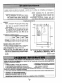
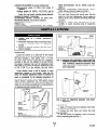
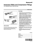
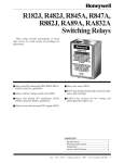
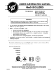
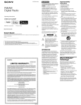
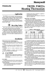
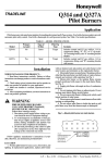
L-/ Honeywell
THE L4017 COMBINATION
FAN AND
LIMIT CONTROL PROVIDES FAN AND
HIGH LIMIT SWITCHING FOR ALL TYPES
OF FORCED AIR HEATING SYSTEMS.
0 The fan switch makes and the limit switch
breaks on temperature rise.
0 The control may be used in line voltage,
low voltage, or millivolt systems.
0 The sensing element is installed directly in
the plenum duct.
v
o The liquid-filled element operates independently of changes in pressure.
0 Electrical circuits are switched
snap switches.
0 Temperature
by reliable
settings are adjustable.
U Fast response sensing elements.
o The sensing element may be bent away
from an obstruction if necessary.
0 Models available with a manual fan switch.
TRADELINE
MODELS
Tradeline models are selected and packaged to provide ease of stocking, ease of handling, and maximum replacement value. Tradeline model specifications are the same as those of standard models except as noted below.
TRADELINE MODELS AVAILABLE:
L4017B Combination
Fan and Limit Control.
MANUAL-AUTO fan switch, 60 inch [I524
mm] capillary sensing element. Includes limit
stop adjusting tool and element support bracket.
STANDARD
-_
I
L4017B Combination
Fan and Limit Control.
MANUAL-AUTO fan switch and 10 inch [254
mm] self-supporting
element. Includes limit
stop adjusting tool.
ADDITIONAL
FEATURES:
Tradeline pack with
cross reference label and special instruction sheet.
MODELS
MODELS:
L4017A Combination
Fan and Limit Control. Unit
has adjustable fan-on and high limit set points with
fixed limit and adjustable fan differentials. With
case and cover.
L4017B Combination
Fan and Limit Control. Unit
has adjustable fan-on and high limit set points
with fixed limit and adjustable fan differentialswith MANUAL-AUTO fan switch. With case and
cover.
ELECTRICAL
DIA. HOLE
IN MTG SJRFACE FOR
DIRECT
IN-
RATING (amperes):
I
Full Load
Locked Rat&.
FAN
I
120v
240V
AC
14
84
AC
7
42
LIMIT
12QV
24QV
AC
8
48
AC
4
24
0.25 amp at 0.25 to 12V dc (limit only).
Maximum connected load- 2000 VA.
MAXIMUM AMBIENT TEMPERATURE: 190 F [ 88 C]
at switches and 300 F [ 149 C] at sensing element.
LIMIT DIFFERENTIAL:
Fixed at 25 F [ 14 C].
SWITCH ACTION: Fan switch makes at set point
(adjustable differential model) and limit switch breaks
at set point on temperature rise. Fan switch breaks at
set point on model with fixed differential on temperature fall.
WHOLESALER OR YOUR DISTRIBUTOR,
COMPLETE ORDERING NUMBER.
SPECIFY1. MODEL NUMBER,
2. SELF-SUPPORTING
3. CAPILLARY
FIG.
(CAPILLARY
(continued
REFER TO THE TRADELINE
TRADELINE
IF DESIRED.
ELEMENT OR CAPILLARY.
LENGTH
I-L4017A
AND B DIMENSIONS,
IN INCHES
[MILLIMETERS
IN BRACKETS],
AND LOCATjON OF MOUNTING
HOLES.
MODELS ONLY).
CATALOG
on page 3)
OR PRICE SHEETS FOR
4. OPTIONAL SPECIFICATION,
IF DESIRED.
5. FAHRENHEIT
OR CELSIUS SCALEPLATE
AND RANGES, IF DESIRED.
6. ACCESSORY,
IF DESIRED.
IF YOU HAVE ADDITIONAL QUESTIONS, NEED FURTHER INFORMATION, OR WOULD LIKE TO COMMENT ON OUR
PRODUCTS OR SERVICES, PLEASE WRITE OR PHONE:
I. YOUR LOCAL HONEYWELL RESIDENTIAL DIVISION SALES OFFICE (CHECK WHITE PAGES 0~ PHONE DlR~cT0Ryb
2. RESIDENTIAL DIVISION CUSTOMER SERVICE
HONEYWELL INC., 1885 DOUGLAS DRIVE NORTH
MINNEAPOLIS, MINNESOTA 55422 (612) 542-7500
(IN CANADA-HONEYWELL
CONTROLS LIMITED, 740 ELLESMERE ROAD, SCARBOROUGH, ONTARIO MIP 2VB)
INTERNATIONAL SALES AND SERVICE OFFICES IN ALL PRINCIPAL CITIES OF THE WORLD.
NENT RECOGNIZED: File No. MP466, Guide No.
MBPR-2.
CANADIAN
STANDARDS
ASSOCIATION
CERTIFIED: File No. LR1620, Guide No. 400-E-0.
OPTIONAL SPECIFICATION:
L4017A Combination
Fan and Limit Control with fan-off scale. Unit has
fixed fan and limit differentials.
Fan-on setting is
fixed at 33 F [19 C] above fan-off setting. With case
and cover.
ACCESSORY: Adapter plate bag assembly, Part No.
21136E, to match mounting holes of competitive
devices.
LENGTH OF ELEMENT (in inches) [millimeters] :
Self-supporting
model-10
[254] (total length of
element).
Capillary models-24
[609.6], 36 [914.4], and 54
[ 1371.61 (flexible capillary length). Add 6 [ 152.41
inches for total length including sensing element.
SENSING ELEMENT: Liquid-filled.
ADJUSTMENT MEANS: Indicators are inside cover.
MOUNTING MEANS: Two holes in backplate.
DIMENSIONS: See Fig. 1.
FINISH: Gray.
UNDERWRITERS
LABORATORIES
INC COMPO-
WRONG
1. Installer
must
be a trained,
experienced
serviceman.
2. Disconnect electricity before connecting wiring
to prevent
electrical
shock or equipment
damage.
3. Conduct a thorough checkout after the installation is complete.
ELEMENT
TOO FAR
FROM HEAT SOURCE
ELEMENT
I
AIR FLOW
AVERAGE
DISCHARGE
TEMPERATURE
ELEMENT
IN
DEAD AIR
LOCATION
ELEMENT
Locate the control on a solid area of the furnace
casing or jacket or on the discharge plenum. The standoff plate furnishes a heat barrier, and a l/4 inch
[6.4 mm] thick asbestos washer (Part No. 106638) is
provided to slip over the capillary for air seal between
the element clearance hole and the diaphragm power
head (see Fig. 4). Since the ambient temperature rating
is 190 F [88 C] at the switches, this heat barrier
should be adequate for all normal applications.
Locate element where it will be exposed to rapid
temperature
changes in the furnace. After the fan
starts, the element temperature
should be affected as
much as practicable by the changing temperature
of
the outlet air and receive only enough radiant heat to
reduce element temperature
lag. The element should
not touch any internal part of the furnace. When provided use the furnace manufacturer’s recommendations
to determine the exact location (Fig- 3).
‘,~~$“‘“”
EXCHANGER
FIG. 3-PROPER
AND IMPROPER LOCATIONS FOR
SENSING ELEMENT. WHEN PROVIDED, USE
THE FURNACE
MANUFACTURER’S
RECOMMENDATIONS
TO DETERMINE THE EXACT LOCATION.
FIG. 4-USE
OF ASBESTOS
BARRIER.
WASHER
FOR HEAT
MOUNTING
1. Make a 7/8 inch [ 22.2 mm] diameter hole where
the element is to be inserted.
2. Loosen the cover screw and remove the cover
from the L4017.
3. Use the control as a template to mark the location
of the 2 mounting holes (see Fig. 1).
4. Punch or drill the holes for the mounting screws.
SHARP BEND
CAUSES RUPTURE
WRONG
BENDNEXTTO
JOINT CAUSES
2596
RUPTURE
FIG. 2-PROPER
POSITIONING
OF ELEMENT.
Page
3
60-2259
WIRING
5. Insert the element into the element opening and
slip the asbestos washer over the capillary (Fig. 4).
With the 2 screws provided, securely fasten the control
to the furnace casing.
6. Position the element as described in Location
above, bending as necessary. Avoid sharp bends or
repeated flexing with the self-supporting model (Fig. 2).
FLEXIBLE
CAPILLARY
I
Disconnect
to prevent
power supply before connecting wiring
electrical shock or equipment damage.
All wiring must comply with applicable local codes
and ordinances.
Follow the system wiring diagrams
furnished with the burner. Figs. 7 and 8 illustrate the
connections to the L4017. For ease in wiring, 2 conduit
knockouts are furnished at the bottom, and 1 at the top
of the case.
MODEL
The element must be firmly held in position by use
of capillary support, Part No. 107324A, or similar
support (Fig. 5).
A jumper is provided between the fan and the
limit terminals. This jumper is used when both the
fan and the limit switches are switching line voltage
circuits. When the high limit switch is used in the
low voltage circuit, remove this jumper.
SUPPORT ELEMENT
WITH NO. 107324A
SUPPORT
NORMALLY
l-401 7
NORMALLY
OPEN-CLOSE!
ON TEMP.
TEMP. RISE
FIG. 5-CAPILLARY
SUPPORT.
MANUALLY
ON L40178
REPLACEMENT
L4017
OF SIMILAR
DEVICE
BY THE
(LINE VOLTAG
IN SERIES
WITH PRIMARY
CONTROL
CIRCUIT
Adapter plate bag assembly, Part No. 211363, is
available to fit mounting
holes of similar controls
(Fig. 6).
POWER
SUPPLY
A
ADD DISCONNECT
REQUIRED.
MEANS AND OVERLOAD
FAN
MOTOR
PROTECTION
AS
z599pi
FIIG. 7-CONNECTIONS
TO L4017
WITH
SWITCH IN LINE VOLTAGE CIRCUIT
PER IN PLACE).
NORMALLY
CLOSEDOPENS
ON TEMP. RISE
LIMIT
(JUM-
NORMALLY
OPEN-CLOSES
ON TEMP.
MANUALLY
(LOW VOLTAGE)
IN SERIES
WITH PRIMARY
CONTROL
CIRCUIT
POWER
SUPPLY
A
L4017 MTG.
I9.5)
FIG.
6-ADAPTER
PLATE AND DIMENSIONS,
INCHES [MILLIMETERS
IN BRACKETS].
ADD DISCONNECT
REQUIRED.
MEANS AND OVERLOAD
MOTOR
PROTECTION
AS
25008
25981\
FIG. 8-CONNECTIONS
TO THE L4017 WITH LIMIT
SWITCH IN how VOLTAGE CIRCUIT (JUMPER REMOVED).
IN
Page
4
I
LIMIT SETTING
To set the cutout point for the high limit switch,
move the high limit indicator (Fig. 9) to the desired set
point. Follow setting instructions
furnished by the
furnace manufacturer
whenever possible. The limit differential is fixed at 25 F [ 14 C]. The switch breaks
at the setting and remakes 25 F [14 C] below the
set point.
~IMPORTANT~
The high limit setting is provided with a stop
to limit the maximum temperature settmg. Do not
force indicator above this point.
0
KNOCKOUT
CAPILLARY
0
0
04
INDICATOR
INDICATOR
HIGH LIMIT
TERMINAL
AN TERMINAL
FAN SWITCH
STAND-OFF
0
FAN SETTING (ADJUSTABLE
DIFFERENTIAL)
The fan differential is adjustable from 15 to 50 F
[ 8 to 28 C] . The fan switch makes at the set point and
breaks 15 to 50 F [8 to 28 C] below the fan-on
setting, depending on the position of the fan adjustment
dial. To change the setting, move the fan-on indicator
(Fig. 9) to the desired temperature.
Set the fan differential adjustment
dial (Fig. 9) to the desired differential. For constant fan operation (L4017B only),
set the MANUAL-AUTO switch in the manual position.
FAN DIFF.
0
2601
FIG. 9-L4017B
WITH COVER REMOVED.
L4017A
IS SIMILAR
BUT DOES NOT INCLUDE
THE MANUAL FAN SWITCH.
FAN SETTING (FIXED DIFFERENTIAL)
Set the fan indicator to the desired fan-off temperature. The fan will come on 35 F [19 C] above that
setting.
-
CHECKOUT
-
1. Follow the furnace manufacturer’s
instructions
for placing the furnace in operation. If a manual reset Pilotstat control is used, make sure that it is
holding in.
2. Set the thermostat and limit control to call for
heat. The main burner should light.
3. To check the high limit control, disconnect the
fan motor and close all dampers. Set thermostat to
call for heat. Main burner should light. When plenum
temperature reaches limit control setting, main burner
should shut off. When checkout is complete, connect
fan motor and open all dampers.
4. Make sure that the fan operates when the furnace
temperature rises to the setting and shuts off when temperature drops below set point and through the desired
OVERHEATING
FREQUENTLY
FURNACE (LIMIT
CUTS OUT)
SWITCH
1. Make sure fan is operating by jumpering across
the fan terminals. If fan does not operate, check the
wiring.
2. Make sure that fan setting is low enough so that
the hot air is circulated from the furnace before the
plenum temperature nears the high limit setting.
3. If limit switch continues to cut out, check for
obstruction
to airflow through furnace. Inspect for
clogged air filters and improperly
adjusted dampers.
MINNEAPOLIS,
MINN. 55408 INTERNATIONAL
Sales Offices in all principal cities of the world. Manufacturing
in
Canada, Finland, France, Germany, Japan, Mexico, Netherlands,
Spain, Taiwan, United Kingdom, U.S.A.
PRINTED IN U.S.A.
HONEYWELL
Australia,
differential. On fixed differential models, the fan should
operate when furnace temperature rises to setting plus
differential
and shut off when temperature
drops to
setting.