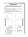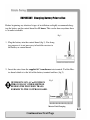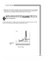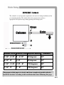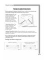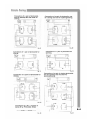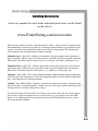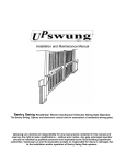
1
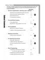
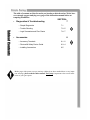
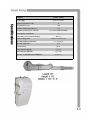
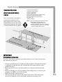
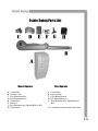
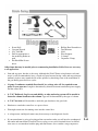
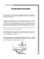
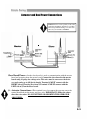
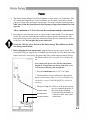
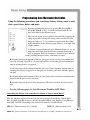
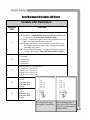
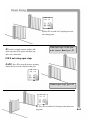
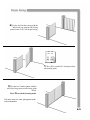
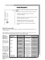
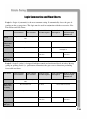
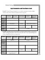
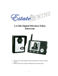
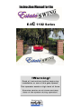
Instruction Manual for the
E-SC 1102 Series
Manufactured by
CE DECLARATION OF CONFORMITY OF MACHINES
(Directive 89/392/EEC, Annex II, Part B)
Manufacturer: FAAC S.p.A.
Address: Via Benini, 1 – 40069 Zola Predosa Bologna – Italy
Declares that: Domolink A.K.A. Estate Swing (USA) mod operator
•
Is built to be integrated into a machine or to be assembled with other machinery to create a machine under the provisions
of Directive 89/392/EEC, and subsequent amendments 91/368/EEC, 93/44/EEC.
•
Conforms to the essential safety requirements of the following EEC directives:
o
73/23/EEC and subsequent amendment 93/68/EEC, 89/336/EEC and subsequent amendment 92/31/EEC and
93/68/EEC.
o
And also declares the it is prohibited to put into service the machinery until the machine in which it will be
integrated or of which it will become a component has been identified and declared as conforming to the
conditions of Directive 89/392/EEC and subsequent amendments assimilated under national laws under DPR
#459 of July 24, 1996.
Bologna, January 1, 2002
Managing Director
A. Bassi
1.
2.
3.
4.
5.
6.
7.
8.
9.
Abassi
Warnings for the installer
General safety obligations
Attention! To ensure the safety of people, it is important that you read all the following instructions. Incorrect installation or incorrect
use of the product could cause serious harm to people.
Carefully read the instructions before beginning to install the product.
Store these instructions for future reference.
This product was designed and built strictly for the use indicated in the documentation. Any other use, not expressly indicated here,
could compromise the good condition/operation of the product and/or be a source of danger.
FAAC declines all liability caused by improper use or use other than that for which automated system was intended.
Do not install the equipment in an explosive atmosphere; the presence of inflammable gas or fumes is a serious danger to safety.
The mechanical parts must conform to the provisions of Standards EN 12604 and EN 12605.
For non-EU countries, to obtain an adequate level of safety, the standards mentioned above must be observed, in addition to national
legal regulations.
FAAC is not responsible for failure to observe Good Technique in the construction of the closing elements to be motorized, of for any
deformation that may occur during use.
The installation must conform to Standards EN 12453 and EN 12445.
The safety level of the automated system must be C+D.
10. Before attempting any job on the system, cut out electrical power and disconnect the batteries.
11. The main power supply of the automated system must be fitted with an all-pole switch with contact opening distance of 3 mm or
greater. Use of a 6A thermal breaker will all-pole circuit break is recommended.
12. Make sure that a differential switch with threshold of 0.03 A is fitted upstream of the system.
13. Make sure that the earthing system is perfectly constructed, and connect metal parts of the means of the closure to it.
14. The automated system is supplied with an intrinsic anti-crushing safety device consisting of a torque control. Nevertheless, its tripping
threshold must be checked as specified in the Standards indicated at point 10.
15. The safety devices (EN 12978 standard) protect any danger areas against mechanical movement risks, such as crushing, dragging, and
shearing.
16. Use of at least one indicator-light (e.g. FAACLIGHT 12VDC) is recommended for every system, as well as a warning sign adequately
secured to the frame structure, in addition to the devices mentioned at point “15”.
17. FAAC declines all liability as concerns safety and efficient operation of the automated system, is system components not produced by
FAAC are used.
18. For maintenance, strictly use original parts by FAAC.
19. Do not in any way modify the components of the automated system.
20. The installer shall supply all information concerning manual operation of the system in case of an emergency, and shall hand over to
the user the warnings handbook supplied with the product.
21. Do not allow children or adults to stay near the product while it is operating.
22. Keep remote controls or other pulse generators away from children, to prevent the automated system from being activated involuntarily.
23. Transit through the leaves is allowed only when the gate is fully open.
24. The user must not attempt any kind of repair or direct action whatever and contact qualified personnel only.
25. Do not short-circuit the poles of the batteries and do not try to recharge the batteries with power supply units other than Master or Slave
cards.
26. Do not throw exhausted batteries into containers for other waste but dispose them in the appropriate containers to enable them to be
recycled.
27. Anything not expressly specified in these instructions is not permitted.
Estate Swing Summery of Functions
The Estate Swing is only to be used for vehicular swing gates in a Class I
setting.
Class I: A vehicular gate opener (or system) intended for use in a home of
one-to-four single family dwelling, or a garage or parking area associated
therewith.
The FAAC Estate Swing automated system was designed and built for controlling
vehicle access. Do not use for any other purpose.
The EstateSwing automated system automates residential swing-leaf gates with
leaves of up to 12’ in length.
It consists of a locking electro-mechanical linear operator, powered by a 12V DC
battery, coupled with control board recharging the battery. The SLAVE equipment
is controlled by the MASTER equipment to which all accessories and pulse generators are connected. The MASTER card can be programmed and is used to set
the following: function logics, work times (by self-learning) and pause times, leaf
speed, and the sensitivity of the anti-crushing device.
The system will automatically lock when the motor is not operating. A release system enables the gate to be moved by hand in case of a system failure.
Keep this manual safely stored after
installation.
Serial Number__________________________
Date of Purchase_______________________
Place of Purchase______________________
Have this information on hand while handling all
service and warranty issues.
This manual and its contents are produced by Web Direct Brands, Inc. and is based on the instructions
written by FAAC,
The table of contents are listed to assist you locating a desired section. We do however strongly suggest studying every page of the instruction manual before attempting installation.
•
Table of Contents
•
•
•
SECTION:
Review of specifications, warnings, parts, and tools
1
» Specifications of the Estate Swing and Components
1.1
» System Overview & Preliminary Checks
1.2
» Estate Swing Parts List
1.3
» Tools Needed for Installation
1.4
Pre-installation charging
» Control Board Layout
2.1
» IMPORTANT: Charging Battery Prior to Use
2.2-.3
Basic Installation
•
3
» IMPORTANT: Setback & Clearance
3.1
» Installation of Mounting Hardware and Arm
3.2-.3
Mounting Control Box
» Finding Location and Mounting
•
2
4
4.1
Pre-Learning Connections
5
» Removable Terminal Strip
5.1
» Installing temporary safety jumpers
5.2
» Actuator Arm and Dual Power Connections
5.3
» Power
5.4
Basic Programming
» Programming Gate Movement Variables
6
6.1
i.e. auto close, speed, force, delays
» Gate Movement Variables LED Chart
6.2
» Complete Start/Stop Learning Process
6.3-.5
The table of contents are listed to assist you locating a desired section. We do however strongly suggest studying every page of the instruction manual before attempting installation.
•
Table of Contents
•
Diagnostics & Troubleshooting
SECTION:
7
» Simple Diagnostics
7.1
» Trouble Shooting
7.2-.5
» Logic Summaries and Flow Charts
7.6-.7
Accessories
8
» Accessory Terminals
8.1-.2
» Photocell& Safety Device Guide
8.3-.4
» Installing Accessories
8.5
Marks pages with opener or usage warnings. Although we have marked these as very important warnings, please read the entire manual. Every step is important to the correct installation of your gate opener.
MODEL
Power Supply
Rated Absorbed Power (W)
Estate Swing
115V AC/ 12V DC
48
Specifications
Max Static Force (N)
1700
Load-free angular speed (in./sec.)
1.25
Length of operator power cable (ft.)
Use frequency (cycles/hour)
Consecutive cycles on charged battery
Battery recharge time
Operating ambient temperature
2.3 CANNOT BE MODIFIED
~5
Max. 15
10 min. for each full cycle
-4 to 131 Deg F
Operator weight (lbs)
4.85
Protection class
IP 44
Gate leaf max length (ft.)
Up to 12
Gate leaf max weight (lbs.)
Up to 550
Operator overall dimensions LxHxD(in.)
See below
1.1
Standard System
Overview and Safety
Zones
The system display to the right is a
recommended standard system.
Other approved accessories can be
installed. Photo sensors and a flashing light indicating gate movement
is recommended for safety purposes.
1,2 Estate Swing Operator
3 Photocells (not included)
4 Master control board
5 Slave control board
6 Push button opening device (not included)
7 Receiver extension (not included)
8 12Vdc flashing lamp (not included)
9 Positive stop
10 AC transformer
Notes: 1) Do not extend operator connection cables
2) When laying electrical cables, use
appropriate rigid and/or flexible tube
3) Do not run any wires in the same conduit as
110 AC power that may be in the area. This
will cause unwanted interference
IMPORTANT
Preliminary Checks:
To ensure safety and an efficiently operating automated system, make sure the following conditions are observed.
•
•
•
•
•
The gate and column must be suitable for being automated. Check that the structure
is sufficiently strong and rigid, and its dimensions and weights conform to those
indicated on page 1.
Make sure the leaves move smoothly without any irregular friction during entire
travel.
Make sure the hinges are in good condition. Ball bearing hinges are ideal for gates
weighing over 200 lbs. or over 10’ in length.
Make sure the gate is plumb and level.
The fence post must be secured in the ground with concrete. This will prevent
alteration of alignments and leveling during installation and during cycles.
1.2
Estate Swing Parts List
Master Operator
A.
B.
C.
D.
E.
F.
G.
H.
Control Box
Operator Arm
Gate Mount Bracket
Post Mount Brackets
Transmitter
Receiver
Post Mounting nuts, Manual Release Key
Transformer
Slave Operator
A.
B.
C.
D.
G.
Control Box
Operator Arm
Gate Mount Bracket
Post Mount Brackets
Post Mounting nuts, Manual Release
Key
34’ 2 conductor stranded direct burial wire
1.3
Tools Needed
•
•
•
•
•
Power Drill
Crescent Wrench
5/16” Drill Bit
Drill bit appropriate to
the anchoring hardware
used
Flat Head Mini Screwdriver
•
•
•
•
•
•
Phillips Head Screwdriver
Tape Measure
Level
Wire Strippers
C-clamps
Carpenters Clamp
Other items that may be needed prior to commencing installation. Bolded items are necessary
to all applications.
•
Start and stop post, bracket or door stop. Although the FAAC Estate swing features soft start/
stop it is still recommended to have a closed stop post because having a start and stop point permanently in place may extend the life of the operator by absorbing some of the momentum of
the gate during open and close cycles.
•
16 gauge 2 conductor stranded direct burial low voltage wire will be required to run
power to your operator. Length is determined by distance between transformer power supply
and the control box.
•
8 - 5/16” Redheads, Lag Screws and shields, or other anchoring system will be needed to
fasten the column brackets to the column. Type will be determined by the type of column.
•
4 - 5/16” hex bolts will be needed to attach the gate brackets to the gate leafs.
•
Hardware to attach the control box to a post or fence.
•
Watertight connectors for running wires into the control box.
•
A voltage meter and digital camera may be necessary to run diagnostic checks.
•
If your transformer is going to be plugged into an outdoor outlet you will need to weatherproof
that outlet and transformer. Electrical boxes or plug covers can be obtained from a local hardware store to accommodate both the plug and transformer. Also consider a surge surpressor.
1.4
Control Board Layouts
ATTENTION: Study the control board and read this section
thoroughly before attempting to operate your gate opener.
Warnings:
• Before attempting any job on the control board (connections, maintenance), turn
off electrical power and unplug the support battery.
• Install a surge protector upstream of your opener, the opener is not power surge
proof nor will power surge damage be covered under warrantee.
• Always separate power from control and safety cables (push-buttons, receivers,
photocells, etc.). To avoid any electrical noise, use separate sheaths or a shielded
cable (with earthed shield).
Layout of Slave Control Board
Layout of Master Control Board
LED
P
P1
P2
F1
J1
J2
J3
J4
J5
Programming LEDs
Power ON and diagnostics LED
“Function” programming push-button
“Value” programming push-button
Battery and motor fuse - F15A
Accessories Terminal board
Transformer Terminal board
Motor connection terminal
Battery connector
Minidec connector/RP receiver
P
F1
J2
J3
J4
Power ON and diagnostic LED
Battery and motor fuse - F15A
Bus connection terminal board
Motor connection terminal board
Battery connector
2.1
IMPORTANT: Charging Battery Prior to Use
Before beginning any electrical stages of installation we highly recommend charging the battery on the control board for 12 hours. This can be done anywhere there
is an outlet available.
Fig 1
1. Plug the battery into the control board (fig 1). For charging purposes it is not necessary to hook the receiver to
the battery or control board.
2. Insert the wires from the supplied AC transformer into terminal J2 of the Master board which is to the left of the battery terminal and fuse (fig 2).
NEVER RUN 110V AC or POWER IN
THROUGH ANY OTHER METHOD
BESIDES THE PROVIDED TRANSFORMER TO THE CONTROL BOARD.
Fig 2
Master Unit Charging
2.2
Continued on Next Page
3. Charge the slave board by wiring it to the master board terminal strip. [terminal 6
of the master must connect with the right side of J2 on the slave and terminal 15
of the master must connect with the left side of the slave] (fig 3)
NEVER CONNECT POWER FROM ANY SOURCE DIRECTLY TO
THE SLAVE BOARD. The slave board may ONLY be connected to the
Master control board.
Let the unit charge for 12 hours, after remove both the transformer power and the
battery. You can now proceed with the installation process.
Fig 3
From Master
ONLY
Slave Charging
2.3
IMPORTANT: Setback
The setback is a very important requirement to be aware of during installation of the
post mounting bracket. The setback allows the operator arm to achieve
appropriate and equal leverage during opening and closing cycles.
Distance - A to B Distance - C to D Degree of Opening
Clearance
1 1/4” - 6 1/3” 4” - 6 1/3”
90 degrees
16”
6 1/3” - 8”
90 degrees
16”
1 1/4” - 3 1/4” 6 1/3” - 8”
110 degrees
20”
1 1/4” - 2”
120 degrees
21”
4 1/3”
7” - 8”
The purpose of this page is to clarify and show examples of possible setbacks.
Install the brackets according to the installation directions following this page.
3.1
Installation of Mounting Hardware and Arm
Examples of stops
1. Set up closed stop points for your gates
if you are choosing to use them. For a snug
closing the master gate should close against
the slave gate using an overlapping bracket
as in the picture to the right. The closed
stop on the ground is for an overall taught
closing point
Examples of industrial
door stops
2. Position the column bracket to the dimensions from the
previous page. In most installations the gate is already hung
so the distance between A and B is going to dictate the
opening degree and distance to set the bracket on the back
of the column. Before securing the bracket, check for levelness.
3. Straighten the arm to it’s full extended position as seen below. This will be the position the
arm will be mounted in the closed position of the gate. See the following page before mounting
the ate bracket.
3.2
4. Using a tape measure, snap line or something else straight, draw a line where the full
closed point of the gates will be. Then from the
center of that line measure in towards the property 1 inch. This will be where the arms in the
fully extended position will mount to the gate.
(Second example to the right)
NOTE: Why do this you may ask. This is because even though the arms have reached
their full extension momentum of the gate
will carry the gate an inch further by just
turning the base gears of the operator.
5. Manually release the opener arms. Do this
by removing the black cap o the top, inserting
the release key and turning it until the gears are free turning.
6. With the arms still fully extended attach the gate mounting bracket to the end of the arm using
the provided nut and bolt. Insert the base of the opener in the column bracket and place the gate
bracket against the gate while the gate is set at an inch open. This will be the correct mounting
position for the gate bracket. After attaching the bracket, be sure to relock the operator arm for
regular operation.
3.3
Finding Location and Mounting Control Box
1. The control box must be mounted near your actuator arm.
The wire on the back of the actuator arm cannot be shortened or
lengthened.
Keep you control box in a location at least 3 feet off the ground to avoid
water buildup.
2. Level your box and mark your mounting holes. The
holes are located in four corners of the control box
(fig 1).
3. After marking your holes drill them and attach the
control box to the post.
4. There are three separate knockouts on the bottom of the
control box. Find a water-tight connector at your local
hardware store that will fit one of the knockout as well
as fit all of your wires through it. Remove the necessary knockout in the bottom of the box and affix a
watertight connection (fig 2).
Fig 1
Fig 2
Your box must be kept watertight. Moisture can damage
your control board.
If you have trouble locating a watertight connector contact Estate Swing
1-800-640-GATE for assistance.
4.1
For Your Convenience
The green numbered terminal strip at
the bottom of the control board is
easily removed for wiring. Simply
pull straight down on the terminal
strip to remove it from the board. It
will slide right off. Slide it back on
when you are finished with your
wiring connections.
5.1
Installing temporary safety jumpers
For your opener to function properly a few connections must be made prior to
the learning process. Accessories should NOT be installed until after the learning process is completed.
Using the provided jumper wire, connect the normally closed safety terminals
(terminals 3, 4, and 5) to one of the negative terminals (terminals 12, 13, 14, or
15). Do this by cutting and stripping the wire into 4 sections and twisting the 3
from the safety terminals together with the fourth which will lead to the common terminal. The connection can be secured with electrical tape or a wire nut.
This allows one terminal to be freed for a safety device but the others to be able
to still be jumped out so the operator will run.
We recommend that these jumpers are later replaced with safety devices after
learning is complete. If you choose not to replace the jumpers with safety devices you MUST keep the jumpers in.
Your connections can be checked using the diagnostics mode. Press P2 once.
C, D, and E should be lit. After checking press P2 again to exit the diagnostics
mode. To learn more about diagnostics see section 7.
5.2
Actuator and Dual Power Connections
Caution! Do not reverse polarity of the wires
connecting the Master and Slave board. This
will cause permanent damage to both boards
and void your warrantee. Caution!
Slave Board Power—On the slave board it is used as communication with the master
board and powering from the master board. Connect the slave board to the master
board using 16 gauge low voltage wire. This wire must be run across the driveway and can be up to 100 feet in length. Terminal 6 MUST connect with the
RIGHT side of J2 on the Slave board, Terminal 15 MUST connect with the
LEFT side of J2 on the Slave board.
J3 - Actuator Connections—This terminal is used to connect the operator arm to the
control board both on the master and slave side. IMPORTANT: Follow the above
chart for wire colors. DO NOT EXTEND OR SHORTEN THE OPERATOR
ARM WIRES.
5.3
Power
1. The Estate Swing (Master Unit if Dual Operator) comes with 1) AC transformer. The
AC transformer supplied has 4 screw terminals, use the center 2 terminals to attach
your low voltage wire (polarity is not relevant). You may locate the transformer up to
1000’ away from the control board with 16 gauge or larger direct burial low voltage wire.
Allow a minimum of 4’ of wire between the transformer and the control board.
2. Insert the two wires into the power in section on the control board (J2) on the master
board. The wires are interchangeable and do not have a positive and negative. The
slave board receives power from the master board only, do not connect power directly
to the slave side. Do not splice the power cable wire.
Never run 110VAC power directly to the Estate Swing. This will destroy the Estate Swing control board.
3. Before plugging in your transformer, plug the battery into the control board. The
clear plastic clip gets clipped into J4 with the clip side on the left. The other side of the
battery wire has a clear plastic disconnect that slides on the battery terminals. Red to
Red, Black to Black. Reversing the wires will blow the
fuse.
Never connect the power wire with the transformer
plugged in. Contact between the two lead wires, even
for a second, will destroy the transformer.
4. Plug the transformer into a 110 V AC outlet.
5. The transformer is not weather proof and must be
kept in a covered area. Plug covers are available from
your dealer, contact 1-800-640-GATE for a dealer in
your area.
6. The power light (P) will be on if the power and battery are connected properly. If
POWER LIGHT
the power light is blinking
slowly then only the battery is
POWER INPUT
connected, check your power
connections.
BATTERY INPUT
5.4
Programming Gate Movement Variables
Using the following procedures you can change factory settings such as auto
close, speed, force, delays and more.
Begin the programming process by pressing P1. Pressing P1 selects A,B,C,D or E. A, B, C, D and E correspond with the variables in the chart on the following page.
When you are on the desired variable you would like to change the
setting of press P2 to change the setting of that variable. P2 will
change the light to 1, 2, 3 or 4 which correspond with the settings
on the chart below on the following page. Below is a list what each
variable controls.
A: Switches between Function Logics. Function Logics are sets of
actions that will occur when an accessory terminal connection is
made or disrupted. Each set of actions is designed to give different
results providing increased safety, convenience or other.
B: Switches between the amount of time the gate pauses before closing after reaching full
open. By selecting Logic EP (4) all pause times will be void and the gate will remain open
until an opening devices is triggered.
C: Switches between the amount of time the gate waits before beginning motion when an
opening and closing is triggered or if dual gates are installed, pause time will only apply to
one gate.
D: Switches between the amount of force the gate opener will exert before an obstruction is
detected and the gate reverses directions.
E: Switches between the speed of the gate motion. This does not effect the soft start and
stop.
See the following page for Gate Movement Variables LED Chart .
Controlling the Master Leaf with either the Master or Slave Control Board
With this function you can select the leaf you wish to move with the Master Control Board.
Press and hold down P1, then press and hold down P2. LED A starts flashing. Using P2 move
from LED 1 to LED 2 according to the desired leaf control as described below:
LED 1 lit - Master controls leaf 1 (default)
LED 2 lit - Master controls leaf 2
6.1
NOTE: The operation of the Slave Control Board is automatically set according to the Master Control Board.
Gate Movement Variables LED Chart
Variable LED Definitions
Function
LED
Function
A
Function Logic — Logic flow chart found on page 18,19
1= A (Automatic - automatically closes the gate depending on the
set pause time. It is the most common setting)
2= S (Safety - designed for higher control and accelerated levels of
safety, also automatically closes the gate)
3= AP (Stepped Automatic - is very similar to automatic (A) but
has a higher amount of safety. It has an increased amount
of motion stop points.)
4= EP (Stepped Semi-automatic - is designed to function similar to
a garage door opener. Turns off the auto close setting.)
B
Pause Times
1= 5 Seconds
2= 10 Seconds
3= 20 Seconds
4= 30 Seconds
C
Master Opening / Closing Delays
1= open 0 sec. / close 0 sec.
2= open 2 sec. / close 2 sec.
3= open 2 sec. / close 4 sec.
4= open 2 sec. / close 8 sec.
D
Static Force
1= Low
2= Medium Low
3= Medium High
4= High
E
Speed
1= Low
2= Medium Low
3= Medium High
4= High
Pressing P1 moves you
through the Letter LEDs
After switching to the desired Letter LED, Pressing
P2 moves you through the
Number LEDs
6.2
Complete Start/Stop Learning Process
Begin by pressing P1 6 times to light A-E simultaneously. While
the 5 LEDs are lit steadily, hold down P2 for about 3 seconds. The
operator will start the maneuver process.
Press for 3
Second
Using P2, Briefly press the button once for each of the
following motion transitions:
Press P2 to teach leaf 1 opening
deceleration starting point.
1)
With open stops, let the gate
make contact, don’t press P2
2) Let the leaf make contact with the full
open stop point. The opener will then stop
and leaf 2 will begin to open.
OR if not using open stops
2 alt.) Press P2 to stop the openers opening
motion and leaf 2 will begin to open.
Without open stops, press P2
6.3
3) Press P2 to teach leaf 2 opening deceleration starting point.
With open stops, let the gate
make contact, don’t press P2
4) Let the leaf make contact with the full
open stop point. The opener will then stop
and reverse directions.
OR if not using open stops
4 alt.) Press P2 to stop the openers opening
motion and reverse the motion of the gate.
Without open stops, press P2
5) Press P2 to teach leaf 2 closing deceleration starting point.
6.4
6) Let the leaf 2 make contact with the
full closed stop point or full closing
point of arm. Leaf 1 will begin closing.
7) Press P2 to teach leaf 1 closing deceleration starting point.
8) Let the leaf 1 make contact with the
full closed stop point or full closing point
of arm.
Press P1 to exit the learning mode.
You may now test your gate opener with
your transmitter.
6.5
Simple Diagnostics
Diagnostics using the Power light on your Master Control
Board.
The P light has a diagnostic function. There are 4 statuses.
1. Steady light indicating main power is ON and
the battery is charged
2. Flashing slowly (lights every second) indicates no main
power but the battery is charged.
3. Flashing quickly (lights every 1/4 of a second)
indicates main power on but discharged battery
4. Light OFF indicates no main power and discharged
battery.
Status of accessory inputs.
The Master Control Board has the ability to verify the status of the terminal board inputs. To access this function:
When all LEDs are off (both lettered and numbered) press P2. The statuses of the accessory terminals in the following chart will be shown in the lettered LEDs column.
LED ON =
Closed Contact
LED OFF =
Open Contact
Normal Operation
idle LED lights
LED
A = OFF
B = OFF
When you have
finished checking,
press P2 again to
C = ON
exit.
If you do not, the
LED status check D = ON
will stay active for
5 minutes and then
the board returns
to all LEDs OFF. E = ON
ON
OFF
A = Terminal 1,
Open/close function
Opening/closing
device is triggered.
Opening/Closing
device is not triggered.
B = Terminal 2,
Single leaf open/
close
Opening/closing
device is triggered.
Opening/Closing
device is not triggered.
C = Terminal 3,
Stop Command
Motion stop device is Motion stop device
in place and not
has been triggered or
triggered or jumper is
is not connected.
in place..
D = Terminal 4,
Opening safety device
Motion stop device is
in place and not
triggered or jumper is
in place..
Safety device has
been triggered or is
not connected.
E = Terminal 5,
Closing safety device
Motion stop device is
in place and not
triggered or jumper is
in place..
Safety device has
been triggered or is
not connected.
WARNING:
When you access
Slave Board is
Slave board is not
1 = OFF if single
1 = Terminal 6,
the input status
connected.
connected.
ON
if
dual
Slave
Board
function all accessories are powered, even with the gate idle. P1 is active and can be used to open and close
the gate.
7.1
Trouble Shooting
If your gate operator arm will not move.
•
Be sure that all safety devices are connected. Safety device terminals work on normally closed connections so if terminals 3, 4, and 5 are not connected to negative
terminals the gate opener will not function. Secondary safety devices are always
recommended by Gate Crafters and FAAC, if you choose to only use the inherent obstruction sensing featured in the Estate Swing control board you must connect terminals 3, 4, 5 to a negative terminal (12, 13, 14, or 15).
•
Be sure your arm is mounted correctly, IF the setback is off there may be not
enough leverage to move the gate.
•
Be sure the power LED is on steady. See page 27 for power LED interpretations.
The battery supplied should be charged for 12 hours before beginning the learning
process.
•
Be sure that the polarity of the arm wiring is correct. For standard Pull-To-Open
operation the Blue wire should be connected to the left and Brown wire connected
to the right. Reverse the polarity for Push-To-Open Operation.
•
Check the fuse to be sure the fuse is not blown. It can be tested visually or with a
volt meter by checking for continuity between the two prongs of the fuse.
•
Check the force setting, D variable. 4 is the highest. Try moving the force to high.
•
Check the speed setting, E variable. If the gate is heavy and tries to move too
quickly, sometimes the jerk of the gate at the beginning may set off the obstruction
sensing. Move the speed setting down to 1.
•
Try removing the opener arm from the gate mounting bracket. Run the cycle with
the arm off the gate. If the opener moves, check your gate for levelness, greased
hinges, and weight/length ratios. Note: moving your gate from the end by hand may
seem very easy. A true test would be moving the gate from the gate mounting
bracket just as the operator would.
If case won’t close or the programming lights will not turn on.
•
Be sure that the control board and the control board cover is fully lined up and
snapped into place. During shipping some shifting may occur resulting in a board
and cover that are not lined up., thus the activation buttons (P1, P2) will not line
up.
7.2
If the power LED (P) is flashing slowly.
•
This means your main power is not on, the battery is low and absorbing too much of the main
power, or the main power was plugged in for less than 5 minutes. Be sure before installation
the battery is charged for 12 hours. A charged battery should read over 13V at idle without
power connected. If your battery is reading under 13V it needs to continue to charge.
Note: When a charging power source is removed from a battery the voltage reading will drop immediately after
and then level out. Please wait for the voltage to level out to get an accurate reading of the battery’s charge.
If the power LED (P) is flashing rapidly.
•
The battery is discharged and does not have enough power to move your gate.
Note: Many times the power light will only flash rapidly for a few seconds during the cycle, at
which time the gate will stop in motion. It may immediately go back to solid. The battery is still
too low, but is closer to being ready to use. This means that the increased amperage pull from
moving a gate is too much for the battery in it’s current level of charge.
If the gate stops mid cycle.
•
Check the force setting, D variable. 4 is the highest. Try moving the force to high.
•
Check the speed setting, E variable. If the gate is heavy and moves too quickly, sometimes the
jerk of the gate during certain parts of the cycle may set off the obstruction sensing. Move the
speed setting down to 1.
•
Try removing the opener arm from the gate mounting bracket. Run the cycle with the arm off
the gate. If the opener no longer stops during cycle, check your gate for levelness, greased
hinges, and weight/length ratios. Note: moving your gate from the end by hand may seem very
easy. A true test would be moving the gate from the gate mounting bracket just as the operator
would.
•
Check the power lights, the flashing may only last a short time when the gate stops. If the light
flashes let your operator charge.
If the gate stops after only a few inches of movement.
•
NOTE: The open and closed position is the most difficult for the opener because it is
working without momentum and at the least leverage point.
•
Check the force setting, D variable. 4 is the highest. Try moving the force to high.
•
Check the speed setting, E variable. If the gate is heavy and moves too quickly, sometimes the
jerk of the gate during the beginning of the cycle may set off the obstruction sensing. Move the
speed setting down to 1.
7.3
•
Try removing the opener arm from the gate mounting bracket. Run the cycle with the arm off
the gate. If the opener no longer stops during cycle, check your gate for levelness, greased
hinges, and weight/length ratios. Note: moving your gate from the end by hand may seem very
easy. A true test would be moving the gate from the gate mounting bracket just as the operator
would.
•
Check the power lights, the flashing may only last a short time when the gate stops. If the light
flashes let your operator charge.
Only the master opens.
•
Check the power light on the slave side be sure the power light is on steady. Note: The slave
does not charge until the master light is steady, if you were recently charging the master and
slave the master might have only gotten a chance to charge.
•
Check the diagnostic mode (Section 17). For dual openers CDE and 1 should be on. The rest
off. If 1 is off then the slave is not communicating with the master, check your connection to
the slave and the polarity of the connection (Section 9).
•
If using an accessory to open the gate, see which terminals it is wired to. Terminal 2 ONLY
opens the master leaf, move your accessory to terminal 1.
•
Check the same information as the first trouble shooting topic “If your gate operator arm
will not move.”
Only the slave will open.
•
Check the same information as the first trouble shooting topic “If your gate operator arm
will not move.”
If your gate is losing memory of slow down points.
•
First reset your gate opener by unplug battery and transformer power for 10 minutes. Plug the
power sources back in and wait for the power light to go steady. Re-program the gate in Complete Stop/Start Learning Process (Section 20).
•
Check the setback. This is very important for the memory process.
For any technical assistance Estate Swing can be reached 9 AM to
5 PM, Monday - Friday. 1-800-640-GATE
7.4
If you call in for technical support or warranty
support: before any control board or motor will be
permitted to be sent in for testing or warranty you will
be required to e-mail digital photos to the technician.
This is done in your best interest to save unnecessary shipping expenses and time lost. Many
times we can come up with solutions to issues by seeing pictures that relay information that is
impossible to relay through a phone conversation.
Below are examples of control board pictures and motor pictures that we will be looking for:
7.5
Logic Summaries and Flow Charts
Logic A - Logic A (automatic) is the most common setting. It automatically closes the gate depending on the set pause time. This logic must be used in conjunction with the accessories: Free
Exit Sensor and Gate Timer.
Gate Status
Gate Status
Result of Result
Termi-of Terminal
Result of TermiResult of Terminal
Result of TermiResult ofResult
Terminal
of Terminal
Result of
Result
Terminal
of Terminal
nal 1 activation
1 activationnal 2 activation
2 activation
nal 4 interruption
4 interruption
5 interruption
5 interruption
4&5 interrupted
simultaneous
Opens leaf
Opens
and leaf
re-closes
and re-closes
after pause
after pause time
time
Re-loads pause time
Open and in
pause
Re-loads pause time
No effect
Open and
in before
re-closing
pause before
re-closing
Re-opens leaf
Closing
NoNo
effect
effect
Closed Closed
Re-opens leaf
Closing
OpeningOpening
Stopped in mid
Stoppedcycle
in
mid cycle
No effect No effect
Closes the leaf
Closes the leaf
No effect
No effect
Re-loads pause time
Re-loads pause time
No effect
Stops motion and
direction
Stops motionreverses
and reverses
direction after
after
interruption
interruption
ReversesNo
direction
No effectReverses direction
Reverses direction
effect
of
motion
of motion
of motion
No effect
No effect
Logic S - Logic S (safety) is designed for higher control and accelerated levels of safety. By triggering an opening device (i.e. push button, transmitter) the gate reverses directions preventing
foreseeable accidents.
Gate Status
Gate Status
Result ofResult
Termi-of Terminal
Result of TermiResult of Terminal
Result of TermiResult ofResult
Terminal
of Terminal
Result of
Result
Terminal
of Terminal
nal 1 activation
1 activationnal 2 activation
2 activation
nal 4 interruption
4 interruption
5 interruption
5 interruption
4&5 interrupted
simultaneous
Opens
and re-closes
after pause time
and leaf
re-closes
after pause
Closed Closed Opens leaf
timeRe-closes the leaf
Open and in
pause
before
Re-closes the leaf
No effect
Open and in
re-closing
pause before
re-closing
Re-opens the leaf
Closing
Re-opens the leaf
Closing
Opening
Opening
Stopped in mid
cycle
Stopped in
mid cycle
Re-closes the leaf
Re-closes the leaf
Closes the leaf
Closes the leaf
No effect
No effect
No effect
effect
NoNo
effect
Closes after 5 secondsafter 5 seconds
Closes
Reverses direction of
motion
Reverses direction of motion
Reverses direction
No effect
of motion
Reverses direction No effect
Reverses direction
No effect
of motion
of motion
No effect
7.6
Logic Summaries and Flow Charts (cont)
Logic AP - Logic AP (stepped automatic) is very similar to automatic (A) but has a higher
amount of safety. It has an increased amount of motion stop points.
Gate Status
Gate Status
Result of TermiResult of Result
Terminal
of TermiResult ofResult
Terminal
of TermiResult Result
of Terminal
of Terminal
ResultResult
of Terminal
of Terminal
nal 1 activation
1 activation
nal 2 activation
2 activation
nal 4 interruption
4 interruption
5 interruption 5 interruption
4&5 interrupted
simultaneous
Closed
Opens
re-closes
leaf and
after
re-closes
pause time
after pause time
ClosedOpens leaf and
Open and in
Open and pause
in
before
pause before
re-closing
re-closing
Closing
Closing
Opening
Stops operation
Stops operation
No effect
Re-opens leaf
Re-opens leaf
No effect
Stops operation
Stops operation
Opening
Stopped in mid
Stopped in
cycle
mid cycle
Closes the leaf
Closes the leaf
No effect
No effect
No effect
Re-loads pause time
Re-loads pause time
No effect
Reverses direction of
Reverses direction
of motion
motion
Stops motion and
No effect
Stops motion and
No effect
Reverses direction
reverses direction
reverses direction
of motion
after interruption
after interruption
No effect
No effect
Logic EP - Logic EP (stepped semi-automatic) is designed to function similar to a garage door
opener. At full open the gate does not re-close after a pause time, it stays open until triggered to
re-close. Logic EP over-rides any set pause time.
Gate Status
Gate Status
Result of TermiResult of Result
Terminal
of TermiResult ofResult
Terminal
of TermiResult of
Result
Terminal
of Terminal
Result Result
of Terminal
of Terminal
nal 1 activation
1 activation
nal 2 activation
2 activation
nal 4 interruption
4 interruption
5 interruption5 interruption
4&5 interrupted
simultaneous
Closed
Closed
Open and in
Open and pause
in
before
pause before
re-closing
re-closing
Closing
Opens leaf
Opens leaf
Re-closes the leaf
Re-closes the leaf
Stops operation
Stops operation
Closing
No effect
No effect
No effect
No effect
No effect
No effect
Reverses direction of
motion
Reverses direction
of motion
Reverses direction
No effect
of motion
Stops operation
Reverses direction
No effect
Reverses direction
Opening
the
No effect
Stopped in mid Restarts motion in opposite direction
of motion
of motion
gate was previously moving before
cycle
stopped
in midthe
cycle
Restarts motion in opposite
direction
No effect
Stopped in
Opening
mid cycle
Stops operation
gate was previously moving before
stopped in mid cycle
7.7
Accessory Terminals
Normally Closed connections must be made for proper gate opener function. The
full accessory board is only found on the master control board.
J1—Terminal Board for Master Card
Terminals
1 - “Open/Close Function” This is a normally open terminal where by any device (i.e. push
button, keypad, receiver) which, by closing a contact, provides an opening and/or closing pulse for both gate leaves (if there is only one leaf, it will control the one leaf).
2 - “Single Leaf Open/Close Function” This is a normally open terminal where by any device (i.e. push button, keypad, receiver) which, by closing a contact, provides an opening and/or closing pulse for only the gate leaf controlled by the master control
board .
3 - “Stop Command” This is a normally closed terminal where by any device (i.e. push
button) which, by opening a contact, halts gate movement. IMPORTANT: If a connection is not made from this terminal to one of the - (negative) terminals (i.e. 12, 13, 14,
15) gate motion will not commence.
4 - “Opening Safety Device” This is a normally closed terminal where by any device (i.e.
photocells, sensitive edge, magnetic loops) which, if there is an obstacle in the area they
protect during opening, reverses gate direction to closing.
If the opening safety devices are tripped when the gate is closed, they prevent the leaf
movement.
IMPORTANT: If a connection is not made from this terminal to one of the - (negative)
terminals (i.e. 12, 13, 14, 15) gate opening will not commence.
8.1
J1—Terminal Board for Master Card (cont.)
Terminals (cont.)
5 - “Closing Safety Device” This is a normally closed terminal where by any device
(i.e. photocells, sensitive edge, magnetic loops) which, if there is an obstacle in the
area they protect during closing, reverses gate direction to opening.
If the closing safety devices are tripped when the gate is open, they prevent the leaf
movement.
IMPORTANT: If a connection is not made from this terminal to one of the (negative) terminals (i.e. 12, 13, 14, 15) gate closing will not commence..
6 - “Slave Control Board Connection” This is a connection between the master and
slave control board. It enables communication between the two equipment and
supplies power to charge the battery on the slave side. Use this in conjunction
with terminal 15 - (negative). Terminal 6 must connect with the right side of J2
on the slave board, Terminal 15 must connect with the left side of J2 on the slave
board.
Caution! Do not reverse polarity of the wires connecting the master and slave
board! This will cause permanent damage to both boards and will void the warranty. Caution!
7, 8 - “Positive (7) & (8) 24 Voltage” Positive 24V for powering accessories that are
run by 24V DC power (i.e. locks, safety devices) while the gate is in motion.
9 - “Indicator Light” When used with terminal 11, this terminal grounds the indicator
light. To avoid compromising correct operation of the system, do not exceed
the indicated power (12V .5Wmax). The indicator light is lit during open, opening
and blocked. The indicator is flashing during closing.
10 - “Lamp” When used with terminal 11 , this terminal grounds the flashing lamp output. To avoid compromising correct operation of the system, do not exceed the
indicated power (12V 21Wmax). When the gate is in motion, the lamp will flash.
11 - “Positive 12 Voltage” This is a 12V terminal used to power the indicator light,
lamp (must be connected to the appropriate ground) and constantly powered accessory devices (when connected to a ground 12,13,14,15) controlled by 12V DC.
(12V 21Wmax)
12, 13, 14 ,15 - “Negatives” Interchangeable negative terminals for use with powered
accessories, safety devices and opening devices.
8.2
Photocell & Safety Device Guide
Before connecting the photocells (or other devices) we advise you to select the type
of operation according to the movement zone to be protected.
Opening Safety Devices: They
operate only during the gate
opening movement and,
therefore, they are suitable for
protecting the zone between the
opening leaves and fixed
obstacles (walls, etc.) against
the risk of impact and crushing.
Closing Safety Devices: They
operate only during the gate
closing movement and,
therefore, are suitable for protecting the closing zone against
the risk of impact.
Opening/Closing Safety Devices: the operate during the gate opening and closing
movements and, therefore, they are suitable for protecting the opening and closing zones
against the risk of impact.
If one or more devices have the same function (opening or closing) they must be
connected to each other in series. Normally Closed contacts on the accessories
panel must be used.
Examples of common wiring layouts
8.3
8.4
Installing Accessories
Accessory manuals for most make and model accessories can be found
on the web at:
www.EstateSwing.com/accessories
The accessory manuals you have or find at the above address may be written to coincide with
that manufacturers model of gate opener. To determine correct terminals on your Estate Swing
operator, use the accessory terminal section of your Estate Swing manual. The following are
some common terms and abbreviations found in manuals:
Normally Open – abbr. N/O – Indicates a circuit that is left open during normal operation of
the gate operator. When a device closes this circuit it signals the operator to perform a function.
This circuit is the main circuit for entry devices. (i.e. keypads, exit wands, push buttons, etc.)
Normally Closed – abbr. N/C – Indicates that in order for the gate opener to be active this circuit must be closed. When a device opens this circuit it stops the motion of the gate operator.
This circuit is the main circuit for safety devices. (i.e. photo eyes, safety loops, etc.)
Common – abbr. COM – This is the matching terminal for both Normally Open and Normally
Closed circuits to be connected to. Accessory wiring that begins in a N/O or N/O terminal must
have a wire that ends in a Common terminal.
Ground – abbr. GND or GRD – Ground is sometimes also known as negative. Common terminals are the same as Ground terminals. Ground can also be the negative spade of the battery if it
is being used in association with positive voltage.
If a device has both a N/O and a N/C wire, both are never used at the same time. Some devices
can be used as either an opening device or a safety device (i.e. gate crafters exit wand, NIR
photo eye, etc.) If being used as an opening device use the N/O and if being used as a safety
device use the N/C terminals.
8.5