1
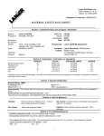
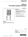
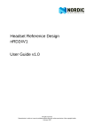
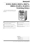
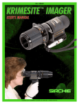
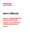
C645A-E
Pressure Switches
PRODUCT DATA
FEATURES
• C645A,B models are for use on natural gas, LP gas,
or air.
• C645B1047 includes a scaleplate stop to meet
American Gas Association (AGA) requirements for
gas-fired boilers with inputs over 2-1/2 million Btuh.
• C645C,D models are for use on air only.
C645A,B,D,E
• C645E for use with distillate fuel oil.
C645C
• Spring-loaded diaphragm actuates snap-acting
Micro Switch.
• Switch can be wired to turn on alarm.
• C645A,C and D models break control circuit on
pressure fall.
• C645B models break control circuit on pressure rise.
• Lockout and manual reset optional in A and C models.
C645A,B with Window
• Removable, zinc-plated cover protects scaleplate and
adjusting screw.
• Lockout models have external manual reset lever.
• Pipe tappings allow selection of positive pressure,
differential-pressure, or venting connections.
• Optional switch position indicator available.
GENERAL
The C645 pressure switches are safety devices used in
positive-pressure or differential-pressure systems to sense
gas or air pressure changes.
• Models of C645A,B available with cover window for
setpoint visibility.
• Buna-N fiber-reinforced material for increased control
diaphragm strength.
• Two seal-off diaphragms for added reliability.
Contents
General ...............................................................................
Features ..............................................................................
Specifications ......................................................................
Ordering Information ...........................................................
Installation ...........................................................................
Settings and Adjustments ...................................................
Operation and Checkout .....................................................
Copyright © 1995 Honeywell Inc. • All Rights Reserved
1
1
2
2
4
6
7
60-2159-8
C645A-E PRESSURE SWITCHES
SPECIFICATIONS
Models:
C645A,C,D Pressure Switches—break a circuit when
pressure falls to scale setting minus the differential.
Refer to Table 1.
C645B Pressure Switches—break a circuit when pressure
rises to scale setting. Refer to Table 1.
C645E—breaks circuit when pressure falls to scale setting
minus the differential. Refer to Table 1.
Table 1. Pressure switch model selection.
Scale
Range
Models (in. wc)
Scale
Range
(kPa)
Max.
Nom.
Max.
1
3
0.2
0.7
5
34.5
Optional
c
1
4
0.2
1.0
5
34.5
Yes
Yes
1
3
0.2
0.7
5
34.5
Optional
Yes
1
4
0.2
1.0
5
34.5
Yes
0.2
0.8
0.05
0.02
1.5
10.3
No
Auto Recycle No
1
3
0.2
0.7
5
34.5
No
Yes
Auto Recycle No
1
3
0.2
0.7
5
34.5
No
Yes
Auto Recycle No
1
3
0.2
0.7
5
34.5
No
Switching
Action
0.7 to
5.2
Yes
Yes
5 to 35
1.2 to
8.7
Yes
Yes
C645B 3 to 21
0.7 to
5.2
Yes
Yes
5 to 35
1.2 to
8.7
Yes
Yes
0.6 to
5.3
0.1 to
1.3
No
Yes
Auto Recycle Optional
or Lockouta
2 to 20 d 0.5 to 5
No
Yes
3 to 21
0.7 to
5.2
No
C645E 3 to 21
0.7 to
5.2
No
C645D
a
Locks out when pressure
b
Locks out when pressure
c
Without indicator on Auto
d
Differential
Range
(kPa)
Nom.
Air
Switch
Position
Indicator
C645A 3 to 21
C645C
Differential
Range
(in. wc)
Maximum
Surge
Pressure
(psi)
Natural
or LP
Gas
Auto Recycle Optional
or Lockouta
Lockoutb
Maximum
Surge
Pressure Cover
(kPa)
Window
falls to setpoint minus differential; can be reset manually after pressure rises to setpoint.
rises to setpoint; can be manually reset after pressure falls to setpoint minus differential.
Recycle; with indicator on Lockout model.
With surge orifice.
Switch Ratings (Amperes):
120 Vac
240 Vac
C645A
Model
Full Load
7.4
3.7
C645B
Locked Rotor
44.4
22.2
Full Load
8.0
5.1
Locked Rotor
48.0
30.6
Full Load
7.4
3.7
Locked Rotor
44.4
22.2
Alternate Electrical Ratings when used with Honeywell
Flame Safeguard Programmers (all C645 models):
C645D
C645C
C645E
Ignition
Transformer
540 VA
Pilot Valve
50
Main Valve
250 VA with 10 times inrush.
400 VA with 2-1/2 times inrush.
All models also rated 2A at 30 Vac.
ORDERING INFORMATION
When purchasing replacement and modernization products from your TRADELINE® wholesaler or your distributor, refer to the
TRADELINE® catalog or price sheets for complete ordering number, or specify—
1. Order number.
3. Optional specifications.
2. Air or gas control on C645A,B models.
4. Accessories, if desired.
If you have additional questions, need further information, or would like to comment on our products or services please write or phone:
1. Your local Honeywell Home and Building Control Sales Office (check white pages of your phone directory).
2. Honeywell Home and Building Control Customer Relations
Honeywell, 1885 Douglas Drive North
Minneapolis, Minnesota 55422-4386
In Canada—Honeywell Limited/Honeywell Limitée, 35 Dynamic Drive, Scarborough, Ontario M1V 4Z9. International sales and
service offices in all principal cities of the world. Manufacturing in Australia, Canada, Finland, France, Germany, Japan, Mexico,
Netherlands, Spain, Taiwan, United Kingdom, U.S.A.
60-2159—8
2
C645A-E PRESSURE SWITCHES
Switching:
Spdt Micro Switch snap-acting switch (Fig. 3).
Canadian Standards Association listed: C645A-E, File no.
LR1620-369, Guide no. 140-A-2; for use subject to
same ambient temperature restrictions as Underwriters
Laboratories Inc.
Factory Mutual Approved.
Industrial Risk Insurers: C645A-D models with window in
cover approvable for applications on burners over
5 million Btuh (5 thousand cfh) input.
Minimum Ambient Temperature:
-20°F (- 29°C).
Maximum Ambient Temperature:
125°F (52°C).
Connections:
1/4-18 NPT female tapping for main or high pressure
connection.
1/8-27 NPT female tapping for venting or low-pressure
connection.
Optional Specifications:
1. C645A with position indicator and manual reset.
2. C645A operation to 1.5 in. WC with position indicator
and manual reset.
3. C645B with position indicator and manual reset.
4. C645C with position indicator and manual reset.
5. C645D with 2 in. (50.8 mm) differential.
Approvals:
Underwriters Laboratories Inc. listed: C645AE File
no. MP2168, Guide no. MFHX; for use in ambient
temperatures normally prevailing in occupiable spaces,
which usually are not higher than 77°F (25°C) but can
occasionally be as high as 104°F (40°C) for brief periods.
Accessories:
1. C645A,B,D: Mounting Bracket: part no. 15865AC.
2. C645C: Mounting Bracket: part no. 112657A.
3. C645A: Cover with Window: part no. 137637B.
4. C645B: Cover with Window: part no. 137637C.
3-1/2 (88.9)
2-7/8 (73)
MOUNTING
BRACKET
(OPTIONAL)
3/16 (2)
(4.8)
4
(101.6)
3-1/2
(88.9)
4-3/4
(120.6)
1/4-18 NPT
1/8-27 NPT
3/8 (9.5)
5/8
(15.9)
1
3/8
(9.5)
1-1/8
(28.6)
2-1/2 (63.5)
1 IMPORTANT: FOR MODELS WITH LOCKOUT, DO NOT OBSTRUCT MANUAL RESET LEVER.
1-5/16
(33.3)
M7564
Fig. 1. Dimensions of C645A,B,D, and E in in. (mm).
3
60-2159—8
C645A-E PRESSURE SWITCHES
3-7/8
(98.4)
MOUNTING BRACKET
(OPTIONAL)
1-1/8
(29)
5/16
(7.9)
3-5/8
(92)
MANUAL
RESET
LEVER
1/4-18 INCH
NPT
3/16 (4.8)
DIA.
1
3/4
(19)
3
(76.2)
5
(127)
1-13/16
(46)
2-5/8
(66.7)
9/32 (7.1)
DIA. (2)
1-1/4
(31.7)
1
(25.4)
1/8-27 INCH NPT
3/4
(19)
2-1/4
(57.1)
7-7/8 DIA. (200)
2-3/4
(69.8)
M7563
1 IMPORTANT: FOR MODELS WITH LOCKOUT, DO NOT OBSTRUCT MANUAL RESET LEVER.
Fig. 2. Dimensions of C645C in in. (mm).
INSTALLATION
When Installing this Product . . .
Mounting
� Read these instructions carefully. Failure to follow them
could damage the product or cause a hazardous
condition.
� Check the ratings given in the instructions and on the
product to make sure the product is suitable for your
application.
� Installer must be a trained, experienced service
technician.
� After installation is complete, check out product
operation as provided in these instructions.
The C645 has a hexagonal fitting with a 1/4 in. NPT tapping,
which is the high pressure connection in differential
applications. The bleed fitting is 1/8 in. NPT female tapped. In
differential pressure control applications using air, connect the
lower pressure to the bleed fitting (Fig. 3 and 4). In
applications using combustible gases, vent the bleed tapping
according to applicable standard code or jurisdictional
authority.
The C645A,B,D can be mounted in any position but are more
accurate when mounted horizontally. The C645C is mounted
with the diaphragm vertical and the bleed fitting at the bottom.
CAUTION
Disconnect power supply before beginning installation
to prevent electrical shock or equipment damage.
60-2159—8
4
C645A-E PRESSURE SWITCHES
OPENING
FOR 1/2 INCH
CONDUIT
The C645E1002 Distillate Fuel Oil Pressure Switch is the
same as the C645A1006 Gas Pressure Switch except that it
does not have a 0.015 in. (0.38 mm) diameter (nominal)
orifice in its 1/4 in. NPT main (high pressure) connection.
(This orifice is required in a C645A Gas Pressure Switch to
restrict gas leakage, but it is too small for oil applications.)
The C645E1002 has a 0.125 in. (3.18 mm) diameter
(nominal) opening in its 1/4 in. NPT main connection into its
pressure chamber.
MANUAL RESET
LEVER
ON LOCKOUT
MODELS ONLY
CAUTION
Vent the bleed tapping back to the oil supply tank—
not to the combustion chamber.
Wiring
COVER
SCREW
Disconnect power supply before connecting wiring to prevent
electrical shock and equipment damage.
SCALE
PLATE
All wiring must agree with applicable codes, ordinances, and
regulations. An opening is provided to accommodate rigid
conduit or armored cable for line voltage operation (Fig. 3
and 4). Do not overload the switch contacts (see Switch
Ratings in Specifications section). The switching schematic is
shown in Fig. 5.
SET POINT
ADJUSTMENT
SCREW
SCALE
PLATE
SET POINT
ADJUSTMENT
SCREW
BLEED
FITTING
M7561
Fig. 4. C645C with cover removed.
BLEED
FITTING
COVER
SCREW
OPENING
FOR 1/2 INCH
CONDUIT
W
2
B
1
MICRO
SWITCH
R
MANUAL RESET LEVER
ON LOCKOUT MODELS ONLY
M7560
Fig. 3. C645A,B,D with cover removed.
1
C645A,C,D BREAKS R-W, MAKE R-B ON PRESSURE FALL.
MANUAL RESET MODELS LOCK OUT.
2
C645B BREAKS R-B, MAKES R-W ON PRESSURE RISE
AND LOCKS OUT.
M7565
Fig. 5. Schematic showing switch in zero
pressure condition.
5
60-2159—8
C645A-E PRESSURE SWITCHES
SETTINGS AND ADJUSTMENTS
Pressure Setpoint Adjustment
Table 4. C645C Control Points.
Tables 2 through 4 give the pressure and switching for each
setpoint. To adjust the pressure setting, turn the setpoint
adjustment screw (Fig. 3 and 4) clockwise
to increase
the pressure setting and counterclockwise
to decrease
the pressure setting.
Setpoint
Switching
Pressure
in. of Water
Pressure
kPa
1a
R-W makes
1
0.25
Table 2. C645A,D,E control points.
Setpoint
Switching
Pressure
in. of Water
3a
R-W makes
3
9b
Pressure
kPa
0.8
R-B makes
2
0.5
R-W makes
9
2.2
15b
R-W makes
15
3.7
21c
R-W makes
21
5.2
R-B makes
18
4.5
R-W makes
35
8.7
R-B makes
31
7.7
35d
a
Nominal differential—1 in. of water (0.2 kPa).
b
Differential between 1 and 3 in. of water (0.2 and
c
Maximum differential—3 in. of water (0.7 kPa).
d
Top
R-W makes
3
0.75
R-B makes
2.6
0.64
5b
R-W makes
5
1.24
R-B makes
4.3
1.2
R-W makes
6
1.50
R-B makes
5.2
1.3
Scale c
C645B1047 Scaleplate Stop Adjustment
The C645B1047 is the same as the C645B1013 except for a
scaleplate stop.
0.7 kPa).
Specifications
Scaleplate Stop:
Limits maximum setting, factory-set at 5-1/4 in. of water
(1.31 kPa).
Setpoint
Switching
Pressure
in. of Water
Pressure
kPa
3a
R-W makes
3
0.8
R-B makes
2
0.5
9b
R-W makes
9
2.2
15b
R-W makes
15
3.7
21c
R-W makes
21
5.2
R-B makes
18
4.5
R-W makes
35
8.7
R-B makes
31
7.7
R-W makes
45
11.2
R-B makes
39
9.8
a
Nominal differential—1 in. of water (0.2 kPa).
b
Differential between 1 and 3 in. of water (0.2 and
c
Maximum differential—3 in. of water (0.7 kPa).
d
Maximum differential—4 in. of water (1.0 kPa).
e
Scale Range:
3 to 21 in. of water (0.75 to 5.23 kPa).
Adjusting Wrench:
Part no. 23466 included with the C645B1047.
To Adjust Scaleplate Stop
� Remove cover.
� Loosen scaleplate stop locking screw about 1/2 turn
counterclockwise
with the 23466 Adjusting
Wrench.
� Move scaleplate stop until bottom edge is aligned with
desired maximum setting.
� Tighten scaleplate stop locking screw clockwise
.
� Replace cover.
0.7 kPa).
Maximum differential—5.7 in of water (1.4 kPa).
60-2159—8
0.2
differential—0.2 in. of water (0.05 kPa).
Differential between 0.2 and 0.8 in. of water (0.05 and
1.2 kPa).
c
Maximum differential—0.8 in. of water (0.2 kPa).
Table 3. C645B control points.
45e
0.8
a
Nominal
b
Maximum differential—4 in. of water (1.0 kPa).
35d
R-B makes
3b
6
C645A-E PRESSURE SWITCHES
The C645B spring-loaded diaphragm actuates the Micro
Switch snap-acting switch which breaks a control circuit, locks
out, and turns on an alarm (if so wired) when the pressure
rises to the scale setting. When pressure falls to the scale
setting minus the differential, the switch lockout can be
manually reset, turning off the alarm
23466 ADJUSTING
WRENCH
LOCKING
SCREW
Checkout
C645A,B—Gas or Air Switch
SCALEPLATE
STOP
� Set cutoff pressure.
� Open main supply line. Depress reset lever on lockout
models until switch makes R-W.
� Set controller and limit switch to call for heat.
� For C645A—close main shutoff valve. Valve should
close when pressure reaches cutoff point.
For C645B—wait a few minutes for the pressure to rise;
then lower the scale setting until the switch makes R-W
and locks out.
M7562
SET POINT INDICATOR
Fig. 6. Adjusting C645B1047 scaleplate stop.
NOTE: To more accurately check C645A, use slow
bleedoff. For C645B, jumper other limit and let
pressure rise to cutoff setting.
Manual Resetting
� For C645A—reconnect the control valve, open the
shutoff valve, press the reset lever (if necessary), and
return the pressure switch to its original setting.
For C645B—raise setting to normal. Depress reset
lever.
� Allow system to operate through at least one complete
cycle to make certain all components are functioning
properly.
The C645A,C manual reset models lock out at scale setting
minus the differential and require manual resetting after the
pressure rises to scale setting to resume normal operation.
The C645B locks out at scale setting and requires manual
resetting after the pressure falls to scale setting minus the
differential to resume normal operation. To reset, push the
reset button as far as it will go; then release.
C645C,D—Air Switch Only
IMPORTANT
Lockout models cannot be made to recycle
automatically by permanently holding in the reset
lever.
� Set cutoff pressure.
� Turn on fan.
� If using a manual rest C645, depress and hold lever
until switch makes R-W.
� Block fan inlet or filter area. Switch should break R-W,
make R-B when pressure drops to cutoff point. Manual
reset models lock out.
� Remove obstruction. Depress reset lever and allow
system to operate through at least one complete cycle
to make certain all components are functioning
properly.
OPERATION AND CHECKOUT
Operation
The C645A,C,D,E spring-loaded diaphragm actuates the
Micro Switch snap-acting switch to break a control circuit
when pressure falls to scale setting minus differential. The
switch can be wired to turn on an alarm at the same time.
When the pressure rises to the scale setting, the control
circuit requires manual resetting to reset and turn off alarm.
Optional C645A model will recycle automatically when the
control circuit returns to scale setting.
C645E1002—Distillate Fuel Oil Switch
� The C645E1002 is the same as the C645A1006 Gas
Pressure Switch except the C645E1002 has a 0.125 in.
NPT main connection in its pressure chamber.
� See Checkout for C645A.
7
60-2159—8
C645A-E PRESSURE SWITCHES
Home and Building Control
Honeywell Inc.
1985 Douglas Drive North
Golden Valley, Minnesota 55422
60-2159—8
60-2159—8 F.P. Rev. 5-95
Home and Building Control
Honeywell Limited-Honeywell Limitée
35 Dynamic Drive
Scarborough, Ontario
M1V 4Z9
8
www.honeywell.com/bbc