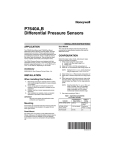
1
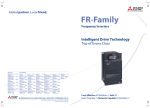
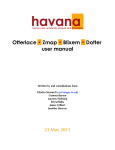
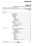
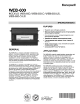
T7300F/Q7300H Series 2000 Commercial Thermostats and Communicating Subbases Contents INTRODUCTION CONSTRUCTION APPLICATION STEPS APPENDIX A ........................................................................................................................... Description of Devices ....................................................................................... Control Application ............................................................................................. Control Provided................................................................................................. Product Names .................................................................................................. Products Covered............................................................................................... Organization of Manual ...................................................................................... Applicable Literature .......................................................................................... Agency Listings .................................................................................................. Abbreviations and Definitions............................................................................. 3 3 3 4 4 5 5 6 6 6 ........................................................................................................................... 7 Performance Specifications ............................................................................... 8 Input/Output Summary .................................................................................. 8 Communications............................................................................................ 9 LonMark® Functional Profile .............................................................................. 10 Configurations .................................................................................................... 10 General.......................................................................................................... 10 ........................................................................................................................... Overview ............................................................................................................ Step 1. Plan The System.................................................................................... Step 2. Determine Required Network Devices................................................... Step 3. Lay Out Communications and Power Wiring ......................................... LonWorks Bus Layout ................................................................................ Cable Termination ......................................................................................... Singly Terminated Network Segment ....................................................... Doubly Terminated Daisy-chain Network Segment .................................. Wiring Details ................................................................................................ Step 4. Prepare Wiring Diagrams ...................................................................... General Considerations................................................................................. Step 5. Order Equipment.................................................................................... Step 6. Configure T7300F/Q7300H.................................................................... Step 7. Troubleshooting ..................................................................................... 11 11 11 12 12 12 14 14 15 15 15 18 19 20 20 ........................................................................................................................... 20 Sequence of Operations.................................................................................... 20 USER ADDRESS NETWORK VARIABLES See form number 63-4366, Q7300 Communicating Subbase System Integration User Address Manual. LonWorks®, LonTalk®, LonMark® and Excel LonSpec™ are U.S. registered trademarks of Echelon® Corporation. ®U.S. Registered Trademark Copyright © 1998 Honeywell Inc. • All Rights Reserved 63- 4365 T7300F/Q7300H SERIES 2000 COMMERCIAL THERMOSTATS AND COMMUNICATING SUBBASES LIST OF FIGURES Fig. 1. Typical T7300F/Q7300H LonWorks® network diagram.......................... Fig. 2. Typical T7300F/Q7300H application. ...................................................... Fig. 3. T7300F/Q7300H dimensions in in. (mm). ............................................... Fig. 4. Functional Profile Number 8060LonMark® Thermostat Object (Type 09) (Thermostat profile variables not used are grayed). ..................... Fig. 5. Connecting personal computer to LonWorks® Bus. ............................... Fig. 6. Typical topology for T7300F/Q7300H devices in LonWorks® network..................................................................................... Fig. 7. Wiring layout for two doubly terminated LonWorks® Bus segments. ..... Fig. 8. Wiring layout for one doubly terminated daisy-chain LonWorks® Bus segment. ............................................................................ Fig. 9. Singly terminated LonWorks Bus termination module. ........................ Fig. 10. Doubly terminated LonWorks® Bus termination modules. ................... Fig. 11. Proper wiring technique. ....................................................................... Fig. 12. Ferrite core wires from Q7300H to digital inputs and outputs. .............. Fig. 13. Typical hookup of T7300F/Q7300H in three-stage heat, two-stage cool heat pump system................................................................. Fig. 14. Typical hookup of T7300F/Q7300H in three-stage heat, two-stage cool heat pump system................................................................. Fig. 15. Typical hookup of T7300F/Q7300H in three-stage heat, three-stage cool conventional system. .......................................................... Fig. 16. Typical hookup of T7300F/Q7300H in two-stage heat, one-stage cool conventional system. ............................................................ 3 4 8 10 11 13 13 14 14 15 15 15 16 16 17 17 LIST OF TABLES Table 1. Additional Products. ............................................................................. Table 2. Terminal descriptions and conditions................................................... Table 3. Application Steps. ................................................................................ Table 4. LonWorks® Configuration Rules and Device Node Numbers.............. Table 5. Field Wiring Reference Table ............................................................... Table 6. Ordering Information. ........................................................................... 63-4365 2 5 9 11 12 18 19 T7300F/Q7300H SERIES 2000 COMMERCIAL THERMOSTATS AND COMMUNICATING SUBBASES INTRODUCTION Control Application Description of Devices The T7300F/Q7300H Series 2000 Commercial Thermostats and Communicating Subbases control 24 Vac commercial single zone heating, ventilating and air conditioning (HVAC) equipment. In addition, the Q7300H can communicate schedule information and system instructions to other devices in a LonWorks® network. Fig. 2 shows a typical T7300F/Q7300H application in a three-stage heat and two-stage cool heat pump system. For additional T7300F/Q7300H hookups, see Fig. 13, 15, 16. The Q7300H Subbase is a LonMark® certified device that provides networking capability for the T7300F Thermostat in a LonWorks® system using a transformer-coupled Free Topology Transceiver (FTT). See Fig. 1. The T7300F/Q7300H communicates with all LonMark® devices including the following: Other T7300F/Q7300H Commercial Thermostat/Communicating Subbases. — Excel 15 S7760A Command Display. — Excel 10 W7750A,B Constant Volume Air Handler Unit (CVAHU) Controller. — Excel 15 W7760A Building Manager. — Excel 10 W7761A Remote Input/Output (RIO) Controller. BUILDING MANAGER NOTEBOOK PC 1 4 8 12 WALL MODULE 16 EXCEL 15 W7760 EXCEL 10 CVAHU 17 30 31 23 37 44 RS-232 SERIAL PORT SLTA S7760 Back LonWorks® BUS T7300 Select MODEM BUILDING MANAGER 1 4 8 12 WALL MODULE 16 EXCEL 15 W7760 EXCEL 10 CVAHU 17 MODEM 23 30 31 37 44 RS-232 SERIAL PORT SLTA S7760 Back LonWorks® BUS T7300 Select M16083B Fig. 1. Typical T7300F/Q7300H LonWorks® network diagram. 3 63-4365 T7300F/Q7300H SERIES 2000 COMMERCIAL THERMOSTATS AND COMMUNICATING SUBBASES SUBBASE AS AS DISCHARGE AIR SENSOR X Y2 Y1 E O G W1 B 3 A1 A2 R C5 C4 C3 C2 C1 T T EB EB AUX. HEAT COMPRESSOR CONTACTOR 2 FAN RELAY COMPRESSOR CONTACTOR 1 LonWorks® BUS HEAT CHANGEOVER VALVE CA2 CA1 CA4 CA3 T T T7147 REMOTE COMFORT ADJUST MODULE GND CA5 EM. HT. RELAY ECONOMIZER COOL CHANGEOVER VALVE 2 1 L1 (HOT) LonWorks® BUS 4 L2 1 POWER SUPPLY. PROVIDE DISCONNECT MEANS AND OVERLOAD PROTECTION AS REQUIRED. 2 USE ECONOMIZER INSTRUCTIONS FOR INSTALLATION INSTRUCTIONS. 3 USE A1 AND A2 WHEN CONTACTS ARE NORMALLY CLOSED IN OCCUPIED MODE. 4 CONNECT GND TO EARTH GROUND. TRANSFORMER M16056 Fig. 2. Typical T7300F/Q7300H application. Communicating subbases for T7300F Thermostats add value by allowing remote-site access—via telephone lines—for diagnostics, maintenance and monitoring. In addition, the T7300F can act as the user interface for onsite Excel 10 Controllers (after initial installation with Excel LonSpec™) without the need for a personal computer workstation. Through the T7300F/Q7300H Thermostat/Communicating Subbase, a building operator can control Excel 10 devices by setting occupancy schedules, setpoints and additional features. Product Names When combined with the T7300F Series 2000 Commercial Thermostat, the Q7300H Communicating Subbase communicates with other devices in a LonWorks® network. The thermostat and subbase are available in the following models: Part Number Control Provided The Q7300H communicates with other network devices, or nodes, for the purpose of sharing data. Through the network, the T7300F/Q7300H sets and deletes schedules. Schedules can be bypassed by selecting Continuous Unoccupied or Temporary Override. By using network messaging, the Q7300H sets fan operation (ON, AUTO) and system mode (HEAT, COOL, AUTO, OFF, EM HEAT) designated by a remote T7300F. Schedules can be programmed for seven days with four designated periods per day; Occupied 1, Occupied 2, Unoccupied 1 and Unoccupied 2. In external schedule mode, the T7300F changes occupancy through a network-based scheduler. In local schedule mode, the T7300F changes occupancy through an internal scheduler. If the external schedule is not periodically updated, the T7300F defaults to the local schedule. The T7300F/Q7300H is also able to provide time of day, temporary setpoint, bypass status and additional information to multiple Excel 10 devices by sending instructions from one T7300F/Q7300H to the Excel 10 devices. When the T7300F is configured to schedule temporary setpoint and effective bypass information for other devices, certain restrictions apply such as: — When the T7300F is scheduling temporary setpoints for Excel 10 devices, the Excel 10 cannot adjust setpoints using the T7770 wall module. — When the T7300F is providing effective bypass information to Excel 10 devices, the Excel 10 cannot change the bypass status using the T7770 wall module. 63-4365 4 Product Description Q7300H2003 Communicating subbase with O and B terminals for three-stage heat, two-stage cool heat pump system. Q7300H2011 Communicating subbase without O and B terminals for three-stage heat, twostage cool heat pump system. Q7300H2029 Communicating subbase for three-stage heat, three-stage cool conventional system. Q7300H2037 Communicating subbase for two-stage heat, one-stage cool conventional system with valve two-position heat output. T7300F2002 Series 2000 Commercial Electronic Thermostat without system and fan switching. T7300F2010 Series 2000 Commercial Electronic Thermostat with system and fan switching. T7300F/Q7300H SERIES 2000 COMMERCIAL THERMOSTATS AND COMMUNICATING SUBBASES Products Covered Organization of Manual This System Engineering manual describes how to apply the T7300F Thermostat and Q7300H Communicating Subbase and related accessories to typical applications. Devices include: T7300F Series 2000 Commercial Thermostat. Q7300H Series 2000 Communicating Subbase. Excel 15 W7760A Building Manager. This manual is divided into four basic sections: 1. Introduction. Provides an overview of the T7300F/Q7300H, discusses related devices, lists additional literature, and provides a glossary of abbreviation and terms. 2. Construction. Describes T7300F/Q7300H features, network connections and dimensions. 3. Application Steps. A step-by-step procedure that provides the information necessary to plan and lay out the T7300F/Q7300H application and accurately order materials. 4. Appendix. Appendix A provides a sequence of operations for configuring network controllers. Excel 10 Controllers, as follows: W7750A,B Constant Volume Air Handler Unit (CVAHU) Controller. W7761 Remote Input/Output (RIO) Controller. Other products: Q7751A,B Bus Router. Q7760A Serial LonTalk Adapter. Q7740A,B FTT Repeaters. 209541B FTT Termination Module. The organization of the manual assumes a project is being engineered from start to finish. If you are changing an existing system, refer to the Table of Contents for relevant sections. See Table 1 for additional products. Table 1. Additional Products. Part Number Product Description Comments R8242A Contactor, 24 Vac coil, DPDT. — AT72D, AT88A, etc. Transformers. — 4074EYD Wallplate for T7770 Wall Modules. For covering an existing hole in a wall. — Serial Interface Cable, male DB-9 to female DB-9 or female DB-25. Obtain locally from any computer hardware vendor. Honeywell (US only) AK3791 (one twisted pair) AK3792 (two twisted pairs). LonWorks® Bus (plenum): 22 AWG (0.325 sq mm) twisted pair solid conductor, nonshielded or Echelon approved shielded cable. Level IV, 140°F (60°C) rating. Honeywell (US only) AK3781 (one twisted pair) AK3782 (two twisted pairs). LonWorks® Bus (nonplenum): 22 AWG (0.325 sq mm) twisted pair solid conductor, nonshielded or Echelon approved shielded cable. Level IV, 140°F (60°C) rating. Honeywell AK3725 (US only), typical or equivalent. Inputs: 18 AWG (1.0 sq mm) five wire cable bundle. Standard thermostat wire. Honeywell AK3752 (US only), typical or equivalent. Outputs/Power: 14 to 18 AWG (2.0 to 1.0 sq mm). NEC Class 2, 140°F (60°C) rating. Honeywell AK3702 (US only), typical or equivalent. 18 AWG (1.0 sq mm) twisted pair. Non-plenum. Honeywell AK3712 (US only), typical or equivalent. 16 AWG (1.3 sq mm) twisted pair. Non-plenum. Honeywell AK3754 (US only), typical or equivalent. 14 AWG (2.0 sq mm) two conductor. Non-plenum. 5 63-4365 T7300F/Q7300H SERIES 2000 COMMERCIAL THERMOSTATS AND COMMUNICATING SUBBASES Applicable Literature ABBREVIATIONS AND DEFINITIONS The following list of documents contains general information related to the T7300F/Q7300H Series 2000 Commercial Thermostats and Communicating Subbases. Application—A specific Building Control function. Form No. Binding—The process of logically connecting network variables in one node to network variable(s) in other node(s). Binding is performed by a network management node that writes the binding information into the EEPROM memory of all the neuron's involved. The binding information is saved in the network image of each neuron. Title 62-0125 T7300F Series 2000 Commercial Microelectronic Conventional or Heat Pump Thermostat Installation Instructions 62-0155 Q7300H Series 2000 Commercial Thermostat Installation Instructions 74-2976 Excel LonSpec™ Specification Data 74-2977 Excel LonSpec™ Software Release Bulletin Command Display—A device that can be used to monitor and change parameters. 74-2937 Excel LonSpec™ User’s Guide 74-2982 Light Commercial Building Solutions System Specification Data 74-2865 E-Bus Wiring Guidelines User’s Guide Control Loop—A primitive control function. A type of function in a node that includes processes, loops and programs. A node can contain one or more control loops. (In Excel 10 class devices, the control loop occupies the entire node.) 74-2967 Excel 15 W7760A Building Manager Specification Data Building Manager—A LonMark® certified device that can be used to monitor and control HVAC equipment and other miscellaneous loads in a distributed network. CVAHU—Excel 10 Constant Volume Air Handler Unit Controller. 95-7565 Excel 15 W7760A Building Manager Installation Instructions 74-2969 Excel 15 W7760A Building Manager System Engineering 74-2956 Excel 10 W7750A,B CVAHU Controller Specification Data HVAC—Heating, Ventilating and Air Conditioning. 95-7521 Excel 10 W7750A,B CVAHU Controller Installation Instructions I/O—Input/Output. 74-2958 Excel 10 W7750A,B CVAHU Controller System Engineering 74-2698 Excel 10 W7761A RIO Controller Specification Data 95-7539 Excel 10 W7761A RIO Controller Installation Instructions 74-2699 Excel 10 W7761A RIO Controller System Engineering 74-2697 T7770A, B, C, D, E, F, G Wall Module Specification Data 95-7538 T7770A, B, C, D, E, F, G Wall Module Installation Instructions 95-7554 Excel 10s—A family of application - specific HVAC controllers such as the Excel 10 CVAHU and Excel 10 RIO. LonWorks® Network—A data network based on neurons communicating with each other using the LonTalk® protocol. Mandatory Mechanisms/Objects/Network Variables— Mandatory mechanisms and network variables that are implemented in all the Excel 10 devices. NamedObject—Objects that have names are called NamedObjects. These objects are visible on the network as functional independent entities and are accessed by name. Typical examples of NamedObjects are Controllers, ControlLoops and LogicFunction blocks. Network Management Node—A LonWorks® node that is responsible for configuring the network, installing the nodes, binding the network variables between nodes, and general network diagnostics. 209541B Termination Module Installation Instructions Agency Listings European Community Mark (CE): Conforms to requirements of European Consortium Standards. 63-4365 6 T7300F/Q7300H SERIES 2000 COMMERCIAL THERMOSTATS AND COMMUNICATING SUBBASES Network Variables—A class of variables defined in Neuron C that allows communication over the LonWorks® network to other nodes on the network. An output network variable in one node can be bound to corresponding input network variable(s) in other node(s). Changing the value of the output network variable in one node causes the new value to be automatically communicated to the bound input network variable(s) in other node(s). When an input network variable is updated, an nv_update_occurs event is posted at the receiving node(s) so that the application program can take action based on the change. A network management node that explicitly reads and/or writes the network variable can also poll network variables. Network variables can contain one data field (one or two bytes) or multiple data fields (a structure). RIO—Excel 10 Remote Input/Output device. RTC—Real Time Clock. Schedule—The structure that defines the occupancy states, setpoints and the time of the changes between these states. SGPU—Significant Event Notification and Guaranteed Periodic Update. SGPUC—Significant Event Notification and Guaranteed Periodic Update with Change Field. SLTA—Serial LonTalk® Adapter. Adapts the transformer coupled LonTalk® messages to the RS-232 Serial Port. Node—A device implementing layers one through six of the LonTalk® protocol including a Neuron® Chip, transceiver, memory, and support hardware. SNVT—Standard Network Variable Type. SCPT—Standard Configuration Parameter Type. Notebook PC—Portable personal computer. Optional Mechanism/Object/Network Variables— Optional mechanisms and variables that shall be implemented on an as-needed basis. However, a different mechanism or network variable cannot be implemented if an existing optional mechanism or network variable can perform the same function. CONSTRUCTION The T7300F Thermostat has a keypad for setting system parameters, a corresponding LCD display and a flip-down keypad cover. The T7300F Thermostat mounts on the Q7300H Subbase. Programmable Controller—A controller that has a variable number of control loops of different types and is user-programmed to execute an application. The user can select the number and type of control loops. The user also has the capability of generating new types of control loops. The Q7300H Communicating Subbase includes LonWorks® Bus terminals and a jack for temporary network connections to a personal computer. A service pin push button provides service messaging to physically locate the device on the LonWorks® network. The subbase mounts horizontally on the wall or on a 2 in. x 4 in. junction box. Recovery Mode or Recovery Period—The time in unoccupied periods when the temperature control is adjusting the control setpoint so that the space temperature reaches the occupied setpoint when the schedule change occurs. Fig. 3 shows T7300F/Q7300H dimensions. 7 63-4365 T7300F/Q7300H SERIES 2000 COMMERCIAL THERMOSTATS AND COMMUNICATING SUBBASES 6-11/16 (170) 1/16 (2) 3-3/16 (77) 1-3/8 (35) 1-7/8 (47) 4-1/8 (105) 1-11/16 (43) 7-5/16 (186) Set Program Set Temperature Run Program Occupied Start Time Unoccupied Start Time Day Temporary Occupied Set Current Day/Time Clear Start Time Copy Continous Unoccupied 7/8 (22) Occupied Temp Unoccupied Temp Change Time/Temp 4-5/8 (117) Heat/Cool Settings System Fan M16086A Fig. 3. T7300F/Q7300H dimensions in in. (mm). Performance Specifications Differential: 2°F (1°C). Electrical Ratings: Power: 20 to 30 Vac, 50/60 Hz. System Current: 6 VA maximum at 30 Vac, 50 or 60 Hz. Humidity Ratings: 5% to 90% RH, noncondensing. Input/Output Summary: Temperature Ratings: Setpoint Range: Heating: 40°F to 90°F (4°C to 32°C; Cooling: 45°F to 90°F (7°C to 32°C). Operating: 40°F to 110°F (4°C to 43°C). Shipping: -20°F to +130°F (-29°C to +54°C). Display Accuracy: ±1°F (+0.5°C). 63-4365 Table 2 summarizes the T7300F/Q7300H Thermostat/Subbase inputs and outputs. 8 T7300F/Q7300H SERIES 2000 COMMERCIAL THERMOSTATS AND COMMUNICATING SUBBASES Table 2. Terminal descriptions and conditions. Standard Terminal Designations A1, A3 A2 AS,AS B BM C1, C2, C3, C4, C5 E EB, EB FC G Typical Connection Function Terminal Type Damper control relay. See T7300F Installation Instructions, form 69-1025-3, installer setup 18, for control parameters. Output Dry contract Dry auxiliary contact. (A2 is common to A1, A3.) Input — C7150B Discharge Air Sensor connection. Input — Heating changeover valve. Output 24V powered contact ML7984 Actuator connection. No call for heat; valve closed during occupied periods and open during unoccupied periods. Output — Input/Output Low power Output 24V powered contact Input/output Communications Input — Communication input for T7147. Emergency heat relay. LonWorks® Bus connection to LonWorks® network. Fan control transformer. Fan relay. Output — GH High speed fan output. Activated during call for cooling. Output — GL Low speed fan output. Activated on call for heat and fan On selection. Output — O Cooling changeover valve. Output — Input, output — P1, P2 Pump interlock relay. Operates circulator pump in hydronic heat or energizes conventional heat system. R 24V system transformer. Input — RC 24V cooling transformer. Input — RH 24V heating transformer. Input — RM ML7984 Actuator connection. No call for heat; valve closed. Call for stage 1 heat; valve approximately one-half open. Call for stage 2 heat; valve fully open. Output — T, T Remote sensor input for T7047 or T7147. Input — W1 Stage 1 heating relay or auxiliary heat relay. Output — W2 Stage 2 heating relay Output — Stage 3 heating relay Output — Input — 24V output on Y — W3 X Heating transformer common. Y Cool call. Y1 Stage 1 compressor contactor. Output — Y2 Stage 2 cooling compressor (conventional). Stage 2 compressor contactor (heat pump). Output — Y3 Stage 3 cooling compressor. Output — verification and future expansion of the network. It also minimizes unknown or inaccurate wire run lengths, nodeto-node (device-to-device) distances, node counts, total wire length, inaccurate repeater/router locations, and misplaced or missing terminations. LonWorks® networks can be configured in a variety of ways; refer to the E-Bus FTT Network Wiring Guidelines, form 74-2865-1, for a complete description of network topology rules and maximum wire length. If longer runs are required, add a Q7740A 2-way or Q7740B 4-way repeater to extend the LonWorks® Bus length. Add a Q7751A to partition the system into two segments to double the length of LonWorks® Bus. Communications The Q7300H provides networking capability in a LonWorks® system when using a Free Topology Transceiver (FTT) transformer-coupled communications port running at 78 kilobits per second (kbs). The transformer-coupled communications interface offers a much higher degree of common-mode noise rejection while ensuring dc isolation. LonWorks® FTT networks are very flexible and convenient to install and maintain, but it is imperative that the network layout be carefully planned and accurate documentation created and maintained. This aids in compliance 9 63-4365 T7300F/Q7300H SERIES 2000 COMMERCIAL THERMOSTATS AND COMMUNICATING SUBBASES Approved cable types for LonWorks® Bus communications wiring are Level IV, 22 AWG (0.34 sq mm) plenum or non-plenum rated unshielded, twisted pair, solid conductor wire. For nonplenum areas, use US part AK3781 (one pair) or US part AK3782 (two pair). In plenum areas, use US part AK3791 (one pair) or US part AK3792 (two pair). Other Echelon approved cable may also be used. Run communications wiring in a conduit, if needed, with non-switched 24 Vac or sensor wiring. The Free Topology Transceiver (FTT) communications LonWorks® Bus supports a polarity insensitive, free topology wiring scheme that, in turn, supports star, loop, and/or bus wiring. NOTE: For additional information on the LonMark® Functional Profile, see the LonMark® Application Layer Interoperability Guidelines and the LonMark® Functional Profile: Thermostat. Both documents are available from LonMark® at internet address: www.lonmark.org. CONFIGURATIONS General The T7300F/Q7300H can be configured to perform a variety of activities in which data is sent to and/or received from other nodes on the LonWorks network. LonMark® Functional Profile The Q7300H supports the LonMark® Functional Profile Number 8060,Thermostat Object (Type 09). See Fig. 4. Information that can be shared with other network devices includes: — Day-of-week and time-of-day — System mode (HEAT, COOL, AUTO, OFF, EM HEAT) — Current fan setting (ON, AUTO) — Space temperature — Current setpoint — Occupied/Unoccupied schedule commands — Current occupancy status — Relay status (heat/cool stages and fan) — Alarm status — Alarm log Hardware Output Thermostat Object Type Number 09. nv1 nviSetpoint SNVT_temp_p Mandatory Network Variables nv2 nvoHeatOutput SNVT_ lev_percent nv3 nvoCoolOutput SNVT_ lev_percent nv4 nvoSpaceTemp SNVT_ temp_p nv5 nvoUnitStatus SNVT_hvac_status nv6 nviSpaceTemp SNVT_ temp_p nvoTerminalLoad nv11 SNVT_ lev_percent nv7 nviOccCmd SNVT_occupancy nv12 nvoEffectSetpt SNVT_ temp_p nv8 nviApplicMode SNVT_hvac_mode nv9 nviSetptOffset SNVT_ temp_p Optional Network Variables A network configuration tool is used to configure Q7300Hs and other nodes with which the Q7300H interacts. The following is a brief description of the configurable features that can be commanded over the network: • Day-of-Week/Time-of-Day: When a T7300F Thermostat is designated as the network time master, the current time of day and day of week is synchronized across the network every minute. Whenever the time of day or day of week of the time master is changed, it automatically adjusts all the other T7300Fs on the network. When a T7300F is controlled by a time master, its time cannot be changed using its keypad. If an attempt is made to change its time, the controlled T7300F LED displays LOC. • System Switch Settings: System switch settings (HEAT, COOL, AUTO, OFF, EM HEAT) can be designated by a remote T7300F, or if configured to allow it, from the T7300F keypad. • Fan Settings: Fan settings (ON, AUTO) are selected as designated by a remote T7300F, or from the T7300F keypad. • Space Temperature: If a valid space temperature value is received at the Q7300H DestRmTemp network variable input, that value will be used in the T7300F as the primary controlled variable. In this case, the internal space sensor of the T7300F is ignored. • Current Setpoint: If a valid setpoint value is received at Q7300H DestSetPoint, that value will be used by the Q7300H as the center setpoint. The heat and cool setpoints are then calculated from this value and are used in the T7300F as the occupied setpoints. During unoccupied periods, DestSetPoint is ignored. nvoTerminalfan nv13 SNVT_switch nv14 nvoEnergyHoldOff SNVT_switch nviEnergyHoldOff nv10 SNVT_switch Configuration Properties nc49 - nciSndHrtBt nc48 - nciRcvHrtBt nc64 - nciMin Delta nc17 - neiLocation nc60 - nciSetPnts nc79 - nciUpSPHeat nc80 - nciLrSPHeat nc76 - nciUpSPCool nc77 - nciLrSPCool SNVT_time_sec SNVT_time_sec SNVT_temp_p SNVT_str_asc SNVT_temp_setpt SNVT_temp_p SNVT_temp_p SNVT_temp_p SNVT_temp_p (mandatory) (optional) (optional) (optional) (mandatory) (optional) (optional) (optional) (optional) Manufacturer Defined Section Hardware Input M16087A Fig. 4. Functional Profile Number 8060LonMark® Thermostat Object (Type 09). (Thermostat profile variables not used are grayed). 63-4365 10 T7300F/Q7300H SERIES 2000 COMMERCIAL THERMOSTATS AND COMMUNICATING SUBBASES • Schedule: The occupancy schedule used by a T7300F may reside locally in that device or remotely in another schedule device (T7300F or Excel 15). Local schedules can be created and modified using the T7300F keypad, or with a configuration tool. External schedules can also be modified using the keypad of the schedule device, or with a configuration tool. When a T7300F receives scheduling information over the network, the user is locked out from making schedule changes at the keypad, and the LCD displays LOC if attempted. When a T7300F Thermostat is designated as a schedule device, it sends its schedule file to the appropriate Q7300H(s) which, in turn, overwrites any existing internal schedule in their T7300F Thermostat. The T7300F/Q7300H Thermostat/Subbase can provide scheduling information to multiple Excel 10 devices by taking instruction from one T7300F/Q7300H and sharing the information with the desired Excel 10 devices. • Occupancy Bypass: Any internal schedule in the T7300F is overridden if a valid occupancy command is received by its Q7300H (resulting from an existing external schedule on the LonWorks network). • Continuous Unoccupied: In this mode, the T7300F Thermostat sets the operating setpoints to the unoccupied setpoints. The T7300F remains in this mode until the Run Program key is pressed. • Setpoint Changes: Selecting a temporary setpoint modifies that setpoint for the present schedule period. Pressing Run Program terminates temporary setpoints. Temperature setpoint range is 40°F to 90°F (4°C to 32°C). • Temporary Override: Modifies the schedule to operate the thermostat in occupied mode for a designated number of hours. Temporary occupied time can be selected for 1, 3, 8 or 12 hours. If a change from occupied to unoccupied is scheduled and the Temporary Override key is pressed, the thermostat remains in occupied mode until the designated override time expires. If the thermostat is in the unoccupied mode when the Temporary Occupied key is pressed, the thermostat operates at the occupied setpoint until the override time expires. Table 3. Application Steps. Step Description 1 Plan the system. 2 Determine required network devices. 3 Lay out communications and power wiring. 4 Prepare wiring diagrams. 5 Order equipment. 6 Configure T7300F/Q7300H. 7 Troubleshooting. Step 1. Plan the System Plan the use of the T7300F/Q7300H Thermostat/Subbase according to the job requirements. Determine the location and functionality. Verify the sales estimate for the number of other controllers and devices required. Check the number and type of other required accessories. When planning the system layout, consider potential expansion possibilities for future growth. Planning is very important if HVAC systems and controllers are to be added in future projects. NOTEBOOK PC SHIELDED INTERFACE CABLE RS-232 SERIAL PORT T7300 Q7760 SLTA CABLE PART NO. 205979 LonWorks® BUS PORT M10102B Fig. 5. Connecting personal computer to LonWorks Bus. Refer to the E-Bus Wiring Guidelines, form 74-2865 for a complete description of network topology rules. See Application Step 3. Lay Out Communications and Power Wiring, for more information on bus wiring layout and Fig. 6 through 10 in Application Step 4. Prepare Wiring Diagrams, for wiring details. APPLICATION STEPS Overview Refer to the Excel LonSpec™ User Guide, form 74-2937, to configure the W7760A Building Manager, W7750A,B and W7761 Controllers and the Q7300H Subbase. The application steps shown in Table 3 are guidelines for configuring the T7300F/Q7300H Thermostat/Subbase in a LonWorks® Bus network and explain the network role of the T7300F/Q7300H. 11 63-4365 T7300F/Q7300H SERIES 2000 COMMERCIAL THERMOSTATS AND COMMUNICATING SUBBASES In addition, a 209541B Termination Module may be required. Refer to the E-Bus Wiring Guidelines, form 742865, and the Excel 10 FTT Termination Module Installation Instructions form, 95-7554, or if Excel 15s are present, see Application Step 3. Lay Out Communications and Power Wiring in the W7760A System Engineering Guide, form 74-2969. Step 2. Determine Required Network Devices A maximum of 60 nodes can communicate on a single LonWorks Bus segment. Each LonWorks Bus device comprises one node. If more than 60 nodes are needed, a Q7751A Router or Q7740 Repeater is necessary. In a network with Excel 15 devices, a router allows up to 120 controller nodes per network, divided between two LonWorks Bus segments. A router or repeater allows up to 120 controller nodes per network, divided between two LonWorks Bus segments. The router comprises two nodes (one node on each side of the router). Router and operator access nodes are not counted in the maximum controller node totals. All devices are able to talk to each other through the router. Step 3. Lay Out Communications and Power Wiring LonWorks® Bus Layout The communications LonWorks Bus, is a 78-kilobit network that uses transformer isolation and differential Manchester encoding. Multiple operator terminals can be connected to the LonWorks Bus at the same time. Table 4 summarizes the LonWorks Bus segment configuration rules. The Free Topology Transceiver (FTT) LonWorks communications Bus supports a polarity insensitive, free topology wiring scheme, refer to the E-Bus Wiring Guidelines form, 74-2865, for a complete description of LonWorks network topology rules. Refer to the E-Bus Wiring Guidelines, form 74-2865, for a complete description of network topology rules and maximum wire lengths. If longer runs are required, use a Q7740A 2-way or Q7740B 4-way repeater to extend the length of the LonWorks Bus. Each network segment can only have one repeater. If more nodes or longer distances are required, add a router or repeater to limit bus traffic or boost distance. Fig. 6 shows a typical wiring diagram for the T7300F/Q7300H in a LonWorks® network. Fig. 7 and 8 show wiring layouts for two doubly daisy-chained LonWorks Bus segments. Table 4. LonWorks Bus Configuration Rules and Device Node Numbers. One LonWorks Bus Segment Maximum Number of Controller Nodes 60 Maximum number of Excel 10s 60 nodes (minus number of Excel 15s) Maximum number of Excel 15s 4 nodes Total 60 nodes maximum Two LonWorks Bus Segments; with Excel 15 Controllers, more than 60 devices Maximum Number of Controller Nodes 112, plus two nodes for router access. One Q7751A,B Router 2 nodes Maximum number of Excel 15s 8 nodes Maximum number of Excel 10 RIO devices 24 nodes Maximum number of Excel 10s (20 per each Excel 15) 112 nodes (minus number of RIOs) Total 122 nodes maximum Two LonWorks Bus Segments; without Excel 15 Controllers, more than 60 devices Maximum Number of Controller Nodes 120, plus two nodes for router access. One Q7751A,B Router 2 nodes Maximum number of Excel 10s (60 per segment) 120 nodes Total 63-4365 122 nodes maximum 12 T7300F/Q7300H SERIES 2000 COMMERCIAL THERMOSTATS AND COMMUNICATING SUBBASES NOTEBOOK PC T7300 T7300 T7300 T7300 RS-232 LonWorks® BUS SLTA T7300 MODEM MODEM RS-232 LonWorks® BUS SLTA T7300 T7300 T7300 T7300 MODEM RS-232 LonWorks® BUS SLTA M16063A Fig. 6. Typical topology for T7300F/Q7300H devices in LonWorks network. 209541B TERMINATION MODULE LonWorks® BUS SEGMENT NUMBER 1 T7300 EXCEL 10 T7770 EXCEL 10 EXCEL 10 CVAHU CVAHU CVAHU 209541B TERMINATION MODULE 209541B TERMINATION MODULE LonWorks® BUS ACCESS LonWorks® BUS SEGMENT NUMBER 2 BUILDING MANAGER 1 4 8 12 T7300 T7300 Q7751A FTT E-BUS ROUTER 16 EXCEL 15 W7760 17 23 30 31 37 209541B TERMINATION MODULE 44 LonWorks® BUS SEGMENT NUMBER 2 EXCEL 10 EXCEL 10 EXCEL 10 CVAHU CVAHU CVAHU M16084C Fig. 7. Wiring layout for two doubly terminated LonWorks Bus segments. 13 63-4365 T7300F/Q7300H SERIES 2000 COMMERCIAL THERMOSTATS AND COMMUNICATING SUBBASES LonWorks® BUS EXCEL 10 CVAHU EXCEL 10 LonWorks® BUS T7770 EXCEL 10 EXCEL 10 RI0 RI0 EXCEL 10 T7300 209541B TERMINATION MODULES (AT ENDS OF LonWorks® BUS T7300 DAISY-CHAIN) CVAHU RI0 T7770 WITH NO LonWorks® BUS ACCESS T7300 T7300 BUILDING MANAGER 1 4 8 12 16 EXCEL 15 W7760 T7300 T7300 EXCEL 10 T7300 T7300 RI0 17 23 30 31 37 44 LonWorks® BUS T7770 WITH NO LonWorks® BUS ACCESS EXCEL 10 EXCEL 10 EXCEL 10 EXCEL 10 RI0 CVAHU RI0 RI0 T7770 LonWorks® BUS T7770 T7770 T7770 JACK FOR OPERATOR TERMINAL I/O CONNECTIONS M16085B Fig. 8. Wiring layout for one doubly terminated daisy-chain LonWorks segment. Cable Termination The FTT network segment requires termination for proper data transmission performance. Use a 209541B Termination Module to connect two of the three termination module wires to the LonWorks Bus terminals. C1 C2 C3 C4 C5 EB EB Singly Terminated Network Segment In a singly terminated topology segment, only one termination is required and can be placed anywhere on the segment. Singly terminated segments use the yellow and brown wires. Mount the termination modules on the appropriate terminals as shown in Fig. 9. BROWN X T T AS AS YELLOW ORANGE PART NO. 209541B TERMINATION MODULE M16202 Fig. 9. Singly terminated LonWorks Bus termination module. 63-4365 14 T7300F/Q7300H SERIES 2000 COMMERCIAL THERMOSTATS AND COMMUNICATING SUBBASES 2. Securely tighten each terminal screw. 3. Push excess wire back into the hole. 4. Plug the hole with nonflammable insulation to prevent drafts from affecting the thermostat. Doubly Terminated Daisy-Chain Network Segment In a doubly terminated daisy-chained topology segment, two terminations are required, one at each end of the topology segment. Doubly terminated segments use the orange and brown wires. Mount the termination modules on the appropriate terminals as shown in Fig. 10. For additional wiring information, refer to the E-Bus Wiring Guidelines, form 74-2865, and the Excel 10 FTT Termination Module Installation Instructions, form 95-7554. NOTE: After wiring, check that all connections are tight and secure. See Fig. 11. Loose or intermittent wire connections can cause inconsistent system operation. C1 C2 C3 C4 C5 EB EB X T T AS FOR WRAPAROUND INSERTION STRIP 7/16 IN. (11 MM). AS FOR STRAIGHT INSERTION STRIP 5/16 IN. (8 MM). M4826 Fig. 11. Proper wiring technique. BROWN Wiring Details ORANGE PART NO. 209541B TERMINATION MODULE LonWorks® network cable should be wired separately from the power and I/O wires when installing Q7300s. If this is not possible, use a minimum of 4 in. (102 mm) separation between split ferrite cores (Fair-Rite 0443164151, or equivalent Honeywell part no. 229997CB, containing five split ferrite cores) to ensure compliance with Class B limits (does not apply to Class A limits). See Fig. 12. to apply ferrite cores to LonWorks® Bus input and output. YELLOW C1 C2 C3 C4 C5 EB EB BROWN X T T AS 1. AS WIRES TO Q7300H COMMUNICATING SUBBASE ORANGE PART NO. 209541B TERMINATION MODULE WIRES TO ALL INPUTS AND OUTPUTS YELLOW 2. WIRES TO ALL INPUTS AND OUTPUTS M16122 Fig. 10. Doubly terminated LonWorks Bus termination modules. CAUTION M10886A Electrical Shock Hazard. Power supply can cause electrical shock. Disconnect power supply before beginning installation. WIRES TO Q7300H COMMUNICATING SUBBASE Fig. 12. Ferrite core wires from Q7300H to LonWorks® inputs and outputs. Step 4. Prepare Wiring Diagrams 1. Loosen the terminal screws on the subbase and connect the system wires. See Fig. 11. Fig. 13 through 16 show T7300F/Q7300H terminal arrangements and provide detailed wiring diagrams. Reference these diagrams to prepare the site-specific job drawings. IMPORTANT Use 18-gauge, solid-conductor color-coded thermostat cable for proper wiring. If using 18gauge stranded wire, do not use more than two wires. Do not use larger than 18-gauge wire. 15 63-4365 T7300F/Q7300H SERIES 2000 COMMERCIAL THERMOSTATS AND COMMUNICATING SUBBASES SUBBASE AS AS X DISCHARGE AIR SENSOR Y1 G Y2 E EM. HT. RELAY COMPRESSOR CONTACTOR 1 W2 W3 HEAT RELAY 2 2 A2 A3 A1 W1 R C4 C3 C2 C1 LonWorks® BUS CA5 CA4 CA3 CA2 CA1 T T T7147 REMOTE COMFORT ADJUST MODULE GND HEAT RELAY 3 HEAT RELAY 1 LonWorks® BUS 3 1 COMPRESSOR CONTACTOR 2 EB EB T T ECONOMIZER 4 FAN RELAY C5 L1 (HOT) L2 1 POWER SUPPLY. PROVIDE DISCONNECT MEANS AND OVERLOAD PROTECTION AS REQUIRED. TRANSFORMER 2 USE A1 AND A2 WHEN CONTACTS ARE NORMALLY CLOSED IN OCCUPIED MODE. USE A2 AND A3 WHEN CONTACTS ARE NORMALLY OPEN IN OCCUPIED MODE. 3 CONNECT GND TO EARTH GROUND. 4 USE ECONOMIZER INSTRUCTIONS FOR INSTALLATION DIRECTIONS. M16057 Fig. 13. Typical hookup of T7300F/Q7300H in three-stage heat, two-stage cool heat pump system (without O/B terminals). SUBBASE AS AS DISCHARGE AIR SENSOR X Y2 Y1 E O G W1 B 3 A1 A2 R C5 C4 C3 C2 C1 T T EB EB AUX. HEAT COMPRESSOR CONTACTOR 2 FAN RELAY COMPRESSOR CONTACTOR 1 LonWorks® BUS HEAT CHANGEOVER VALVE CA2 CA1 CA4 CA3 T T T7147 REMOTE COMFORT ADJUST MODULE GND CA5 EM. HT. RELAY COOL CHANGEOVER VALVE ECONOMIZER 2 1 LonWorks® BUS 4 L1 (HOT) L2 1 POWER SUPPLY. PROVIDE DISCONNECT MEANS AND OVERLOAD PROTECTION AS REQUIRED. 2 USE ECONOMIZER INSTRUCTIONS FOR INSTALLATION INSTRUCTIONS. 3 USE A1 AND A2 WHEN CONTACTS ARE NORMALLY CLOSED IN OCCUPIED MODE. 4 CONNECT GND TO EARTH GROUND. TRANSFORMER M16056 Fig. 14. Typical hookup of T7300F/Q7300H in three-stage heat, two-stage cool heat pump system (with O/B terminals). 63-4365 16 T7300F/Q7300H SERIES 2000 COMMERCIAL THERMOSTATS AND COMMUNICATING SUBBASES SUBBASE AS RC AS Y1 G Y2 Y3 X W3 W2 W1 RH 3 A2 A3 A1 C5 C4 C3 C2 C1 T T EB EB 2 COMPRESSOR CONTACTOR 1 DISCHARGE AIR SENSOR HEAT RELAY 2 COMPRESSOR CONTACTOR 2 ECONOMIZER LonWorks® BUS 5 FAN RELAY CA2 CA1 T CA5 CA4 CA3 T7147 REMOTE COMFORT ADJUST MODULE COMPRESSOR CONTACTOR 3 LonWorks® BUS GND 1 HEAT RELAY 3 L1 (HOT) T 4 HEAT RELAY 1 L1 (HOT) L2 L2 1 HEATING TRANSFORMER COOLING TRANSFORMER 1 POWER SUPPLY. PROVIDE DISCONNECT MEANS AND OVERLOAD PROTECTION AS REQUIRED. 2 JUMPER RC TERMINAL TO RH TERMINAL WHEN INSTALLED ON A SYSTEM WITH ONE TRANSFORMER. 3 USE A1 AND A2 WHEN CONTACTS ARE NORMALLY CLOSED IN OCCUPIED MODE. USE A2 AND A3 WHEN CONTACTS ARE NORMALLY OPEN IN OCCUPIED MODE. 4 CONNECT GND TO EARTH GROUND. 5 USE ECONOMIZER INSTRUCTIONS FOR INSTALLATION DIRECTIONS. M16058 Fig. 15. Typical hookup of T7300F/Q7300H in three-stage heat, three-stage cool conventional system. SUBBASE AS FC AS GL GH X R Y HIGH SPEED FAN RELAY DISCHARGE AIR SENSOR LOW SPEED FAN RELAY RM BM P1 P2 A1 A2 C5 C4 C3 C2 C1 T EB EB T DAMPER CONTROL RELAY ML7984 VALVE ACTUATOR LonWorks® BUS 3 COOLING RELAY CA5 CA4 CA3 CA2 CA1 T T T7147 REMOTE COMFORT GND ADJUST MODULE PUMP INTERLOCK RELAY 1 L1 (HOT) L1 (HOT) L2 L2 LonWorks® BUS 2 1 TRANSFORMER FAN TRANSFORMER 1 POWER SUPPLY. PROVIDE DISCONNECT MEANS AND OVERLOAD PROTECTION AS REQUIRED. 2 CONNECT GND TO EARTH GROUND. M16059 3 SEE TABLE 2 FOR VALVE AND VALVE ACTUATOR MODELS. Fig. 16. Typical hookup of T7300F/Q7300H in two-stage heat, one-stage cool conventional system. 17 63-4365 T7300F/Q7300H SERIES 2000 COMMERCIAL THERMOSTATS AND COMMUNICATING SUBBASES General Considerations Table 5 lists wiring types, sizes and distances for the T7300F/Q7300H and Excel 10 products. The Q73000H accepts 14 through 22 AWG (2.0 to 0.34 sq. mm wire). Table 5. Field Wiring Reference Table. Wire Function Recommended Wire Size (Minimum) Construction Specification or Requirement Distance (Maximum) Vendor Wire Type Thermostat wire. Inputs: 18 AWG (1.0 sq mm) five wire cable bundle. Standard thermostat wire. Honeywell AK3725 (US only), typical or equivalent. Thermostat wire. Outputs/Power: 14 to 18 AWG (2.0 to 1.0 sq mm). NEC Class 2, 140°F (60°C) rating. Level IV, 140°F (60°C) rating. Honeywell AK3752 (US only), typical or equivalent. LonWorks Bus (NonPlenum). 22 AWG (0.34 sq mm) Twisted pair solid conductor, nonshielded or Echelon® approved cable. Level IV, 140°F (60°C) rating. Honeywell AK3781 (one twisted pair), AK3782 (two twisted pair). Refer to E-bus Wiring guidelines Users Guide 74-2865-1 for maximum length. Power Wiring. 14 AWG (2.0 sq mm) Any pair nonshielded (use heavier wire for longer runs). NEC Class II, 140°F (60°C) rating. Honeywell AK3754 (14 AWG) twisted pair), AK3909 (14 AWG) single conductor or equivalent. Limited by line-loss effects on power consumption. 63-4365 18 T7300F/Q7300H SERIES 2000 COMMERCIAL THERMOSTATS AND COMMUNICATING SUBBASES Step 5. Order Equipment After compiling a bill of materials through completion of the previous application steps, refer to Table 6, Ordering Information. Table 6. Ordering Information. Part Number Product Description Comments Q7300H2003 Communicating subbase with O and B Includes AS terminals for optional discharge air terminals for three-stage heat, two-stage cool sensing; A1, A2, A3 terminals for optional heat pump system. economizer. Q7300H2011 Communicating subbase without O and B Includes AS terminals for optional discharge air terminals for three-stage heat, two-stage cool sensing; A1, A2, A3 terminals for optional heat pump system. economizer. Q7300H2029 Communicating subbase for three-stage heat, three-stage cool conventional system. Q7300H2037 Communicating subbase for two-stage heat, Includes AS terminals for optional discharge air one-stage cool conventional system with sensing; A1, A2, A3 terminals for optional valve two-position heat output. economizer. T7300F2002 Series 2000 Commercial Electronic Thermostat without system and fan switching. Use with Q7300H Communicating Subbase for network communications. T7300F2010 Series 2000 Commercial Electronic Thermostat with system and fan switching. Use with Q7300H Communicating Subbase for network communications. W7750A,B Excel 10 Constant Volume Air Handler Unit. Single-speed fan provides continuous supply air to designated area. W7761A Excel 10 Remote Input/Output Device. Service messaging feature identifies physical location of specific Excel 10s on network. — Serial Interface Cable, male DB-9 to female DB-9 or female DB-25. Obtain locally from any computer hardware vendor. Honeywell (US only) AK3791 (one twisted pair) AK3792 (two twisted pairs). LonWorks Bus (plenum): 22 AWG Level IV, 140°F (60°C) rating. (0.325 sq mm) twisted pair solid conductor, nonshielded or Echelon approved shielded cable. Honeywell (US only) AK3781 (one twisted pair) AK3782 (two twisted pairs). LonWorks Bus (nonplenum): 22 AWG Level IV, 140°F (60°C) rating. (0.325 sq mm) twisted pair solid conductor, nonshielded or Echelon approved shielded cable. Includes AS terminals for optional discharge air sensing; A1, A2, A3 terminals for optional economizer. Honeywell AK3725 (US only), Inputs: 18 AWG (1.0 sq mm) five wire cable typical or equivalent. bundle. Standard thermostat wire. Honeywell AK3752 (US only), Outputs/Power: 14 to 18 AWG typical or equivalent. (2.0 to 1.0 sq mm). NEC Class 2, 140°F (60°C) rating. Honeywell AK3702 (US only), 18 AWG (1.0 sq mm) twisted pair. typical or equivalent. Non-plenum. Honeywell AK3712 (US only), 16 AWG (1.3 sq mm) twisted pair. typical or equivalent. Non-plenum. Honeywell AK3754 (US only), 14 AWG (2.0 sq mm) two conductor. typical or equivalent. Non-plenum. 19 63-4365 T7300F/Q7300H SERIES 2000 COMMERCIAL THERMOSTATS AND COMMUNICATING SUBBASES communicated to the Q7300H). The Room Temperature sensor provides the temperature input for the temperature control loop of the T7300F. If both local and remote sensors are available, the two values can be averaged and the resulting value supplied to the temperature control routine. Step 6. Configure T7300F/Q7300H Use Excel LonSpec™ Software to configure the T7300F/Q7300H Thermostat/Subbase for specific applications. The Excel LonSpec™ User’s Guide, form 742937, provides software operation instructions for the personal computer. NOTE: A physical sensor (either local or remote) cannot be averaged with a network sensor. A valid value for the network sensor input gives the network sensor priority over any locally-wired sensors. Step 7. Troubleshooting 1. Check for 24 Vac power. a. Turn on power. b. Use a meter to check for 24 Vac power at the subbase. c. If 24 Vac is not present, check the transformer for secure connections and proper operation. d. If 24 Vac is present at the subbase, turn off the power. If a valid room temperature value is not available to the T7300F/Q7300H, the temperature control algorithm in the T7300F is disabled, causing the heating and cooling control outputs to be turned off. Network Setpoint (DestSetPoint) This is a center-setpoint signal sent from another LonWorks Bus device. When received, it is used to calculate the actual cooling or heating occupied setpoint. The DestSetPoint value becomes the center of the Zero Energy Band (ZEB) between the cooling and heating occupied setpoints. The size of the ZEB is found by taking the difference between the programmed heating and cooling occupied setpoints (CoolOccSpt and HeatOccSpt); therefore, the actual setpoints are found as follows: ActualCoolSpt = DestSetPoint + (CoolOccSpt HeatOccSpt) / 2 ActualHeatSpt = DestSetPoint - (CoolOccSpt HeatOccSpt) / 2 2. Check wiring. a. Inspect all wiring connections at the Q7300H terminals and verify compliance with the job site engineering drawings. b. If any wiring changes are required, first be sure to remove power from the device before starting work. c. Pay particular attention to: Terminal connections. Connect GND to earth ground. Device Wiring. In hookups with A1 and A2 terminals, use A1 and A2 when contacts are normally closed in Occupied mode. In hookups with A2, A3 terminals, use A2 and A3 when contacts are normally open in Occupied mode. O/B Terminals. The Q7300H2003 provides O/B terminals for cool/heat changeover. During unoccupied times, the network setpoint value is not referenced, and the programmed setpoints are used instead (CoolUnoccSpt and HeatUnoccSpt). During occupied times, if DestSetPoint is valid, it will be used to override any internal setpoints. Network Setpoint Offset (DestSptOffset) NOTE: All wiring must comply with applicable electrical codes and ordinances or as specified in installation wiring diagrams. This is a setpoint adjustment signal sent from another LonWorks device. When received, it is used to bump the current setpoint value up or down. The amount of the bump is the value of DestSptOffset itself. The actual setpoints are found as follows: ActualSetpoint = CurrentSetPoint + DestSptOffset APPENDIX A: SEQUENCE OF OPERATIONS During unoccupied times, the network setpoint offset value is not referenced, and the programmed setpoints are used instead (CoolUnoccSpt and HeatUnoccSpt). This appendix provides the network related control sequences of operation for the T7300F/Q7300H. For temperature control related sequences, refer to the T7200D,E, T7300D,E,F and Q7300 Series 2000 Programmable Commercial Thermostat and Subbase Product Data, form no. 63-4355. Setpoint Limits (MinCoolSetPt and MaxHeatSetPt) User-entered setpoint limits are provided by MinCoolSetPt and MaxHeatSetPt. The occupied setpoints used in the control algorithms are limited by these parameters. The lowest actual setpoint allowed in cool mode is equal to MinCoolSetPt, and the highest actual setpoint allowed in heat mode is equal to MaxHeatSetPt. Network Operations Room Temperature Sensor (DestRmTemp) This is the room space temperature sensor. This sensor can be local (contained internally within the T7300F), remote (external but hard-wired back to the Q7300H subbase), or network (physical sensor is located elsewhere on the LonWorks Bus, and its value is 63-4365 20 T7300F/Q7300H SERIES 2000 COMMERCIAL THERMOSTATS AND COMMUNICATING SUBBASES If DestOccSchedule is valid, it has highest priority and determines the occupancy mode; otherwise, the status is determined by the internal schedule of the T7300F. StatusOcc has two possible states: occupied, or unoccupied. Bypass Operation (StatusOcc, DestManOcc and DestBypass) During unoccupied periods, the facility occupant can request that the occupied temperature control setpoints be observed by doing any one of the following: — Depressing the Temporary Occupied button on the T7300F, or — Setting the DestManOcc network point to Bypass, or — Setting the DestBypass network point to ON. NOTE: The T7300F/Q7300H does not support Standby mode. Manual Override of occupancy mode can occur from three sources and is governed by two selectable arbitration schemes. The two schemes are: Network Wins or Last-in Wins, (as set in OvrdPriority). When activated, the thermostat remains in Bypass mode until: — Bypass duration setting has timed out (BypTime), or — User presses the Run button on the T7300F to switch off the Bypass mode, or — Occupancy schedule switches the mode to occupied, or — User sets the DestManOcc network point to occupied, or unoccupied. The three sources of manual override status are: — DestManOccPossible states: Occupied, Unoccupied, Bypass, Standby and Null (not active). If Standby is received, it is ignored. This input source has the highest priority in determining manual override status for a Network Wins arbitration scheme, or in the event there is more than one source change at a time in the Last-in Wins arbitration scheme. Bypass initiates a self-timed bypass of the control unit and expires upon completion of the defined timed period. The controller then treats the bypass status of this input as Null until the next change in status. — DestBypassPossible states: Bypass On, Bypass Off or Not Assigned (not active). This input places the controller in an untimed bypass state or turns off the bypass mode. This source is second in priority to DestManOcc under the same arbitration schemes mentioned above. — The T7300F keypad (Temporary Occupied and Continuous Unoccupied keys). BypassTime BypassTime is the time between the pressing of the override button at the wall module (or initiating bypass mode via DestManOcc) and the return to the original occupancy state. When the bypass state has been activated, the bypass timer is set to BypTime (default of 180 min.). NOTE: A Bypass mode initiated via DestBypass does not cause the bypass timer to run. The DestBypass signal source is assumed to be tracking the duration peiod using its internal bypass timer. Demand Limit Control (DestDlcShed) Override Priority When the Q7300H receives a high-electrical-demand signal, the controller applies a DlcBumpTemp amount to the current actual space temperature setpoint value. The setpoint is always adjusted in the energy-saving direction. This means that if the T7300F is in cooling mode, the DLC offset bumps the control point up and when in heating mode, bumps the control point down. A network bypass signal always has priority over local pushbutton induced overrides. When DestManOcc is not OC_NUL, then the effective occupancy is DestManOcc, regardless of the T7300F keypad-initiated override state. Continuous Unoccupied Mode When returning from a DLC Shed event, the setpoint is gradually ramped back to its original (unbumped) value over a 30-minute period. This mode is entered when the Continuous Unoccupied button on the T7300F is pressed. This mode can also be entered via a network command (DestManOcc set to Unoccupied). If the controller is in this mode, it reverts to the unoccupied setpoints for temperature control. The thermostat remains in this mode indefinitely until the Run button is pressed to exit the mode, or a network command is sent to clear the mode. Start-Up START_UP_WAIT is the first mode after application restart or power-up. During START_UP_WAIT, no control algorithms are active. Occupancy Mode Arbitration (StatusOcc) NOTES: After a controller commission via Excel LonSpec™, the Q7300 is reset and an application restart occurs. Not all network inputs can be received during the START_UP_WAIT period because many network variables are updated at a slower rate; therefore some control decisions can be considered temporarily inappropriate during START_UP_WAIT. The T7300F/Q7300H has multiple sources for occupancy schedule information and, therefore, it employs an arbitration scheme to determine the current actual mode. Time-of-day (TOD) schedule status comes from either one of two sources: — Internal schedule contained in the T7300F, or — DestOccSchedule network input received from another LonWorks device. 21 63-4365 63-4365 22 23 63-4365 Home and Building Control Honeywell Inc. Honeywell Plaza P.O. Box 524 Minneapolis, MN 55408-0524 Home and Building Control Honeywell Limited-Honeywell Limitee 155 Gordon Baker Road North York, Ontario M2H 3N7 Honeywell Latin American Region 480 Sawgrass Corporate Parkway Suite 200 Sunrise, FL 33325 Honeywell Europe S.A. 3 Avenue du Bourget 1140 Brussels Belgium 63-4365 J.S. 12-98 Honeywell Asia Pacific Inc. Room 3213-3225 Sun Hung Kai Centre No. 30 Harbour Road Wanchai Hong Kong Printed in U.S.A. on recycled paper containing at least 10% post-consumer paper fibers. www.honeywell.com