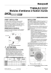
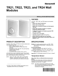
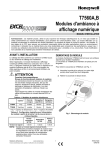
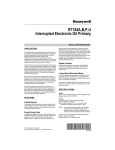
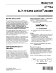
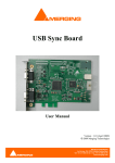
1
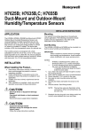
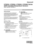
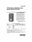
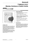
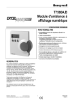
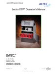
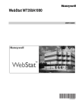
P7640A,B
Differential Pressure Sensors
APPLICATION
The P7640A Panel Mount and P7640B Duct Mount
Differential Pressure Sensors provide reliable, accurate
measurement and control. Proper applications include
measurement of extremely low pressure applications such
as: building/room pressure, air flow, variable air volume,
filter status, and duct pressure. They are ideal for clean
rooms, hospitals, fume hoods, and computer rooms.
The P7640 Pressure Sensors are designed with fieldselectable 4-20 mA, 0-5 Vdc, or 0-10 Vdc output. The four
pressure ranges fall between 0–1 in. w.c./0–250 Pa or 0–
10 in. w.c./0–2500 Pa, depending on the model.
Accessory
INSTALLATION INSTRUCTIONS
Duct Mount
The units with the integral probe should typically be
mounted at the high pressure location when used for
differential control.
CONFIGURATION
Select the proper output, mode, and pressure range
using the switches and jumpers:
1. Select output using the output switch:
a. Current: mA (then skip to step 3), or
b. Voltage: Volt.
2. Select 0-10 Vdc or 0-5 Vdc using jumper J4.
3. Select bi- or uni-directional mode using jumper J5.
NOTE: Setting for 0 to 1 in. w.c. and bi-directional
will give output from -1.0 to 1.0 in. w.c.
32003169-001 Duct Pressure Pick-up Probe, 4 in.
INSTALLATION
When Installing this Product...
1.
2.
3.
4.
Read these instructions carefully. Failure to follow
them could damage the product or cause a hazardous condition.
Check ratings given in instructions and on the
product to ensure the product is suitable for your
application.
Installer must be a trained, experienced service
technician.
After installation is complete, check out product
operation as provided in these instructions.
IMPORTANT
All wiring must agree with applicable codes,
ordinances and regulations.
4.
5.
6.
Select inches w.c. or Pascal scale using jumper J7.
Select fast or standard response time using jumper
J8.
Select appropriate full-scale pressure range using
the rotary switch. Align arrow (not the slot) to the
desired range. See Table 2 for the range selection
guide.
NOTE: Note that either the 1 in. w.c. or 10 in. w.c.
scale is marked. This is the available
scale for that given model. When the
range is changed, the LCD models
momentarily indicate selected range.
7.
Set output according to Table 1.
Table 1. Controller Compatibility
and Output Settings.
Controller
LONSPEC™
Setting
Required Sensor
Output Setting
Mounting
W7750, W7760, W7761
4-20 mA
Screw holes are accessed inside the enclosure (with the
cover removed) and are located in the upper left and
lower right corners.
FilterPress or
P7610B
W7750B, W7760C,
W7753, W7760
0-10 Vdc (default)
FilterPress or
P7610F, or voltage
Non-Honeywell
0-5 Vdc
n/a
Panel Mount
Run tubing from one (static) or both (differential) barb
fittings, making sure the typically higher pressure source
is connected to the port labeled HI, and the typically
lower pressure source is connected to the port labeled
LO.
62-0210-07
P7640A,B DIFFERENTIAL PRESSURE SENSORS
WIRING (FIG. 1 THROUGH 3)
CAUTION
Equipment Damage Hazard.
CAUTION
Equipment Damage Hazard.
Can damage the device beyond repair.
Disconnect power supply before installation.
Can damage the device beyond repair.
Do not apply power to output terminal. Permanent
equipment damage will result.
NOTE: Wiring to the ZERO terminals is optional.
ZERO
ZERO
RESPONSE
FAST/STD
JP8
RESPONSE
FAST/STD
JP8
6
5
6
5
4
3
4
3
3
– +
CONTROLLER,
METER OR
RECORDER
L1
12 TO 30 Vdc
POWER SUPPLY
+
+ INPUT SIGNAL
– COMMON
2
1
L2
+ –
2
2
2
1
3
+ INPUT SIGNAL
– COMMON
1
1
1
VOLT
SV/10V
mA
VOLT
OUTPUT
JP4
VOLT
SV/10V
mA
VOLT
OUTPUT
JP4
CONTROLLER,
METER OR
RECORDER
MODE
BI/UNI
JP5
PWR OUT COM ZERO
MODE
BI/UNI
JP5
PWR OUT COM ZERO
UNITS
IN. W.C./PA
JP7
7
UNITS
IN. W.C./PA
JP7
7
POWER SUPPLY. PROVIDE DISCONNECT MEANS AND OVERLOAD
PROTECTION AS REQUIRED.
POLARIZED SECONDARY INDICATIONS FOR USE WITH DC POWER
SUPPLY ONLY.
–
DRY CONTACT TO AUTOMATICALLY ZERO THE SENSOR
UPON CLOSURE. (OPTIONAL)
1
DRY CONTACT TO AUTOMATICALLY ZERO THE SENSOR UPON
CLOSURE. (OPTIONAL)
M27291
M27292
Fig. 2. Wiring for current (mA) output.
Fig. 1. Wiring for voltage (Vdc) output.
P7640
+
–
+
–
COM
O OUT
COM
19
20
21
22
23
+
–
Vin (Vac)
Gnd
2
O Vo (0-10 Vdc)
O OUT
1
2
3
4
5
6
7
8
9
10
11
12
13
E
GND
AI
1
AI
2
AI
GND
AI
3
AI
4
AI
GND
AI
5
AI
6
AI
GND
AI
7
AI
8
AI
GND
DI
1
DI
2
DI
3
DI
4
25
26
27
28
OUT OUT OUT OUT OUT OUT OUT OUT
1
2
3
4
5
6
7
8
18
+
–
PWR
W7760A
17
H76XX
P7640
PWR
24
1
15
16
ANALOG
OUT
AO
AO
1
2
14
AO
GND
24
24
24
24
24
24
24 OUT 21 GND
VAC VAC VAC VAC VAC VAC VAC COM VDC
COM COM
OUT
GND GND
29
31
32
33
34
35
36
37
38
39
40
E-BUS
41
42
E-BUS
43
44
L1
(HOT)
L2
1
POWER SUPPLY. PROVIDE DISCONNECT MEANS AND OVERLOAD PROTECTION AS REQUIRED.
2
TEMPERATURE SIGNAL CONNECTIONS ARE NOT POLARITY SENSITIVE.
M18302B
Fig. 3. Typical wiring for three-wire pressure sensor with Vdc output (used with the XL15A Controller).
62-0210—07
2
P7640A,B DIFFERENTIAL PRESSURE SENSORS
OPERATION
Table 2. Range Selection Guide.
1-in. Models
Rotary
Switch
Position
0–1
in. w.c.
IMPORTANT
During the first few minutes of operation, readings at zero pressure and lowest pressure
ranges appear erroneous. Following this initial
warm-up period, the P7640 maintains specified
accuracy and stability.
10-in. Models
0–250
Pascal
0–10
in. w.c.
0–2500
Pascal
0
0.1
25
1
250
1
0.25
50
1
250
2
0.5
100
1
250
3
1
250
1
250
4
1
250
2.5
500
5
1
250
5
1000
6
1
250
10
2500
7
1
250
10
2500
The display momentarily indicates “SET” when a selection
is made. In normal operation, pressure indications are in.
w.c.
Zeroing
IMPORTANT
Perform zeroing only when both Zero ports are
exposed to the same pressure.
Zeroing the device automatically resets the output and
displays zero pressure. To do this either:
— Press and hold the ZERO pushbutton for 2 seconds, or
— Provide contact closure on the ZERO terminals. To
ensure this, place a piece of jumper tubing between HI
and LO.
NOTE: To avoid accidental zero, this feature is
enabled only while detected pressure is
within 5% of factory calibration.
3
62-0210—07
P7640A,B DIFFERENTIAL PRESSURE SENSORS
APPENDIX
IMPORTANT
This page is only for models with date code prior to 0816.
Pre 0816 Date Code Configuration
Select the proper output, mode, and pressure range using the switches and jumpers:
1. Select output using the output switch:
a. Current: mA (then skip to step 3), or
b. Voltage: Volt.
2. Select 0-10 Vdc or 0-5 Vdc using jumper J4.
3. Select bi- or uni-directional mode using jumper J5.
NOTE: Setting for 0 to 1 in. w.c. and bi-directional will give output from -1.0 to 1.0 in. w.c.
4.
Select appropriate full-scale pressure range using the slide switch.
NOTE: Note that either the 1 in. w.c. or 10 in. w.c. scale is marked. This is the available scale for that given
model. When the range is changed, the LCD models momentarily indicate selected range.
WIRING (FIG. 4 THROUGH 5)
CAUTION
Equipment Damage Hazard. Can damage the device beyond repair.
Disconnect power supply before installation.
NOTE: Wiring to the ZERO terminals is optional.
ZERO
ZERO
PWR OUT COM ZERO
CONTROLLER,
METER OR
RECORDER
2
3
10" 1"
10 1.0
5 .5
2.5 .25
1.0 .1
– +
MODE
PWR OUT COM ZERO
BI/UNI
VOLT VOLT
5V/10V
BI/UNI
VOLT
VOLT 5V/10V
mA
3
+ –
1
RANGE
10" 1"
10 1.0
5 .5
2.5 .25
1.0 .1
MODE
mA
+ INPUT SIGNAL
– COMMON
RANGE
1
L1
1
L2
2
POWER SUPPLY. PROVIDE DISCONNECT MEANS AND OVERLOAD
PROTECTION AS REQUIRED.
POLARIZED SECONDARY INDICATIONS FOR USE WITH DC POWER
SUPPLY ONLY.
DRY CONTACT TO AUTOMATICALLY ZERO THE SENSOR UPON
CLOSURE. (OPTIONAL)
M22554A
Fig. 4. Wiring for voltage (Vdc) output.
CONTROLLER,
METER OR
RECORDER
+ INPUT SIGNAL
– COMMON
1
12 TO 40 Vdc
POWER SUPPLY
+
–
DRY CONTACT TO AUTOMATICALLY ZERO THE SENSOR
UPON CLOSURE. (OPTIONAL)
M22555A
Fig. 5. Wiring for current (mA) output.
LonSpec™ is a trademark of Echelon® Corporation.
Automation and Control Solutions
By using this Honeywell literature, you agree that Honeywell will have no liability for any
damages arising out of your use or modification to, the literature. You will defend and indemnify
Honeywell, its affiliates and subsidiaries, from and against any liability, cost, or damages,
including attorneys’ fees, arising out of, or resulting from, any modification to the literature by you.
Honeywell International Inc.
1985 Douglas Drive North
Golden Valley, MN 55422
customer.honeywell.com
® U.S. Registered Trademark
© 2014 Honeywell International Inc.
62-0210—07 M.S. Rev. 07-14
Printed in United States