1
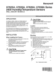
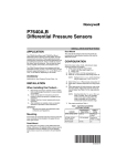
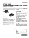
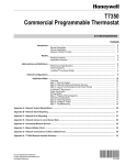
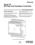
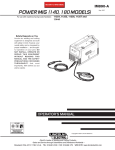
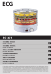
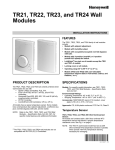
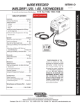
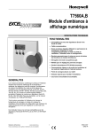
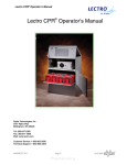
H7625B; H7635B,C; H7655B
Duct-Mount and Outdoor-Mount
Humidity/Temperature Sensors
INSTALLATION INSTRUCTIONS
APPLICATION
The H7625B, H7635B, H7655B Duct-Mount and H7635C
Outdoor-Mount Humidity/Temperature Sensors are
universal Relative Humidity transmitters that can be
powered with either a +18 to 36 Vdc or 24 Vac supply.
The sensors use a half-wave bridge rectifier to convert
AC power to a usable DC voltage. The device also
includes a 20K ohm temperature sensor for optional use.
The humidity sensors are designed with a fieldselectable 4 to 20 mA, 0 to 5 Vdc, or 0 to 10 Vdc output
signal equivalent to 0 to 100% RH. All units are shipped
from the factory with a default setting to accept AC power
with three-wire, 0 to 10 Vdc loop-powered output.
INSTALLATION
Mounting
The method of mounting depends on the particular
sensor application. The following procedures include
outdoor and duct applications. Also refer to the
instructions for the electronic control.
Duct Mounting
The H7625B, H7635B and H7655B can be mounted in a
duct to sense humidity and temperature.
IMPORTANT
Select a location to expose sensor to average
duct humidity and temperature. Avoid locations
where stratification can cause sensing errors.
NOTES:
—
When Installing this Product...
1.
2.
3.
4.
Read these instructions carefully. Failure to follow
them could damage the product or cause a
hazardous condition.
Check ratings given in instructions and on the
product to ensure the product is suitable for your
application.
Installer must be a trained, experienced service
technician.
After installation is complete, check out product
operation as provided in these instructions.
1.
2.
3.
4.
5.
6.
NOTE: The two free wires are thermistor wiring
connections. When connecting these, use
two wire nuts.
CAUTION
Electrical Shock or Equipment Damage
Hazard.
Can shock individuals or short equipment
circuitry.
Disconnect power supply before installation.
H7635C is weatherproof for outdoor use.
Knockouts allow 1/2 in. conduit connection.
—
To avoid damaging board during installation,
the cover can be detached completely:
1.Carefully remove wire plug from board.
2.Set the cover aside.
Cut a hole in the duct just large enough to accept
the sensing element.
Open case by rotating the cover counterclockwise.
Mount standard 1/2 in. conduit to the case.
Use case to mark mounting screw pilot hole
locations.
Drill the pilot holes and fasten the sensor to the
duct.
Wire the sensor. See Wiring section.
7.
Reattach the wire plug and cover being careful not
to pinch wires between the cover and case.
CAUTION
Equipment Damage Hazard.
Improper wiring can damage the sensor
beyond repair.
Follow the wiring instructions carefully.
63-2579—3
H7625B; H7635B,C; H7655B DUCT-MOUNT AND OUTDOOR-MOUNT HUMIDITY/TEMPERATURE SENSORS
Outdoor Mounting
The H7635C senses outdoor air humidity and
temperature. Mount this control where it can sense
average outdoor air humidity and temperature. Normally,
the north side of a building provides a suitable location.
NOTES:
—
—
1.
H7635C is weatherproof for outdoor use.
Knockouts allow 1/2 in. conduit connection.
To avoid damaging board during installation,
the cover can be detached completely:
1.Carefully remove wire plug from board.
2.Set the cover aside.
Open case by rotating the cover counterclockwise.
Output Settings (Table 1)
The board has three switch blocks:
— A six DIP switch block.
— A four DIP switch block.
— A white gang switch on a blue block.
1. Adjust the 4-switch block according to Table 1.
NOTE: The 6-switch block normally requires no
adjustment. (See the Appendix.)
2. Set the gang switch (white switch in blue block) to
correspond with the output (mA or Vdc).
NOTE: See Fig. 1 for DIP switch locations.
Table 1. Controller Compatibility
and Output Settings.
NOTE: Orient case so the element points down.
2.
3.
4.
5.
6.
7.
Required 4-Switch Block Blue and
Sensor
Settings
White
Output
Output LONSPEC™
Setting
Setting 4 3 2 1 Switch
Mount standard 1/2 in. conduit to the case.
Use case to mark mounting screw pilot hole
locations.
Drill pilot holes.
Fasten the case to the wall.
Wire the sensor. See Wiring section.
W7750, W7760, 4-20 mA — On — — 4-20 mA C7600C
W7761
NOTE: The two free wires are thermistor wiring
connections. When connecting these, use
two wire nuts.
W7750B,C
0-10 Vdc On — — On Vout
W7760C,
(default)
W7753, W7760
H7621/31
T7350, XL50,
XL100,
XL500 XF
Modules, XFL
n/a
Reattach the wire plug and cover being careful not
to pinch wires between the cover and case.
Controller
0-10 Vdc On — — On Vout
(default)
Non-Honeywell 0-5 Vdc
On — On — Vout
n/a
OFF
ON
0-10 VDC
NORMAL OPERATION
OFF
OFF
ON
ON
4-20 MA
OFF
ON
0-5 VDC
M22705
Fig. 1. DIP switch locations and settings.
63-2579—3
2
H7625B; H7635B,C; H7655B DUCT-MOUNT AND OUTDOOR-MOUNT HUMIDITY/TEMPERATURE SENSORS
WIRING
For voltage output, shielded cable (16-22 AWG) should
be used.
mA OUTPUT
TRANSDUCER
ONLY
For current output, either shielded cable or twisted pair
(16-22 AWG) can be used.
NOTE: When using shielded cable, ground the shield
only at the controller end (see Fig. 2). Grounding
both ends can cause a ground loop.
18 TO 36 Vdc
POWER SUPPLY
Vin
+
Io
–
CONTROLLER, METER
OR RECORDER
+ INPUT SIGNAL
– COMMON
The 20K ohm NTC temperature output is accessed
through the separate blue and green wires (located inside
the enclosure).
GROUND
M22528
Fig. 2. Typical wiring diagram for transducer with twowire mA output and external DC power supply.
OUTDOOR
AIR
SENSOR
T7770 REMOTE SENSOR
9
T7350
SUBBASE
8
7
T5
6
T6
5
4
T7
3
2
DISCHARGE
AIR
SENSOR
1
T4
HEAT
RELAY 2
T3
OS
OS
AS
AS
HP
M
M
X
RH
COMPRESSOR
CONTACTOR 4
W3/Y4 Y3
COMPRESSOR
CONTACTOR 2
W2
Y2
Y1
G
5
HS
HC
RC
AUX
W1
COMPRESSOR
CONTACTOR 3
Vo Gnd Vin
(0-10 Vdc)
(Vac)
3
MOTION
SENSOR
HEAT
RELAY 1
HUMIDITY SENSOR
4
1
2
FAN
RELAY
COMPRESSOR
CONTACTOR 1
ECONOMIZER
L2
L1
(HOT)
1
POWER SUPPLY. PROVIDE DISCONNECT MEANS AND OVERLOAD PROTECTION AS REQUIRED.
2
ENSURE TRANSFORMER IS SIZED TO HANDLE THE LOAD.
3
HEAT/COOL SYSTEMS WITH ONE TRANSFORMER REQUIRE THE FACTORY-INSTALLED JUMPER.
4
USE ECONOMIZER INSTRUCTIONS FOR INSTALLATION DIRECTIONS.
5
HC AND HP PROVIDE 24 VAC TO THE HUMIDITY SENSOR.
M22529
Fig. 3. Humidity sensor (0-10 Vdc output) wiring with T7350
(use with RH/Temperature combination T7350 units only).
3
63-2579—3
H7625B; H7635B,C; H7655B DUCT-MOUNT AND OUTDOOR-MOUNT HUMIDITY/TEMPERATURE SENSORS
P7640
+
–
+
–
COM
O OUT
COM
19
20
21
22
23
+
–
Vin (Vac)
Gnd
2
O Vo (0-10 Vdc)
O OUT
1
2
3
4
5
6
7
8
9
10
11
12
13
E
GND
AI
1
AI
2
AI
GND
AI
3
AI
4
AI
GND
AI
5
AI
6
AI
GND
AI
7
AI
8
AI
GND
DI
1
DI
2
DI
3
DI
4
25
26
27
28
OUT OUT OUT OUT OUT OUT OUT OUT
1
2
3
4
5
6
7
8
18
+
–
PWR
W7760A
17
H76XX
P7640
PWR
24
1
GND GND
15
16
ANALOG
OUT
AO
AO
1
2
14
AO
GND
24
24
24
24
24
24
24 OUT 21 GND
VAC VAC VAC VAC VAC VAC VAC COM VDC
COM COM
OUT
29
31
32
33
34
35
36
37
38
39
40
E-BUS
41
42
E-BUS
43
L1
(HOT)
L2
1
POWER SUPPLY. PROVIDE DISCONNECT MEANS AND OVERLOAD PROTECTION AS REQUIRED.
2
TEMPERATURE SIGNAL CONNECTIONS ARE NOT POLARITY SENSITIVE.
M18302B
Fig. 4. Typical wiring diagram for 5-wire temperature/humidity sensor with Vdc output
(used with the XL15A controller).
63-2579—3
4
44
H7625B; H7635B,C; H7655B DUCT-MOUNT AND OUTDOOR-MOUNT HUMIDITY/TEMPERATURE SENSORS
CHECKOUT
Converting Output Signal to Percent RH
CAUTION
Equipment Damage Hazard.
Can short electric circuitry.
• Never connect 120 Vac to the transducer.
• Connect only DC voltage to a transducer
intended for DC supply.
NOTE: Use laboratory quality meters and gauges for
applications requiring a high degree of accuracy.
1.
2.
3.
Verify the transducer is mounted in the correct position.
Verify appropriate input signal and voltage supply.
Verify appropriate configuration range.
4 to 20mA Signal
〈 signal [in mA] – 4〉
------------------------------------------------- = percent RH
0.16
Example: 12 mA output signal
(12 - 4)/ 0.16 = 50% RH
0 to 10 Vdc Signal
Example: 8 VDC transmitter signal output
8 Vdc/0.10 = 80% RH
Table 2. Troubleshooting.
Problem
Items to Check
No reading
• Verify correct supply voltage at the power terminal blocks.
• Verify correct wiring configuration and DIP switch settings.
• Verify that terminal screws are connected tightly with all wires firmly in place.
Erratic readings
• Verify all wires are terminated properly.
• Ensure that there is no condensation on the board.
• Verify clean input power. In areas of high RF interference or noise, shielded cable can be
necessary to stabilize signal.
5
63-2579—3
H7625B; H7635B,C; H7655B DUCT-MOUNT AND OUTDOOR-MOUNT HUMIDITY/TEMPERATURE SENSORS
APPENDIX
RH Test and Configuration DIP Switch Settings (Table 3)
IMPORTANT
• Only adjust these switches for troubleshooting or
recalibrating the sensor. (Adjustment is not
normally necessary.)
• For normal operation, always keep DIP switch 3
in the ON position. When DIP switch 3 is off, the
RH transmitter cannot read the sensor. This
inability-to-read forces the output to never
change.
Table 3. Test/Calibration Settings (Six-Switch Block).
Setting
Normal Operation (Default)
6
5
4
3
2
1
— — — On — —
0% RH Output
On — — — — —
50% RH Output
— On — — — —
100% RH Output
— — On — — —
Increment RH Output
— — — — On —
Decrement RH Output
— — — — — On
Reset to Original Calibration
— — — — On On
63-2579—3
0% RH Output (for Testing Only)
Transmitter always outputs a signal of 4 mA or 0 Vdc. The
sensor does not affect the transmitter output.
50% RH Output (for Testing Only)
Transmitter always outputs a signal of 12 mA, 2.5 VDC, or
5 VDC. The sensor does not affect transmitter output.
100% RH Output
Transmitter always outputs a signal of 20 mA, 5 VDC, or
10 VDC. The sensor does not affect the transmitter
output. Sensor doesn’t affect the transmitter output.
Normal Operating Condition
DIP switch 3 must be set in the On position for normal
operation. All other DIP switches must be set Off.
6
H7625B; H7635B,C; H7655B DUCT-MOUNT AND OUTDOOR-MOUNT HUMIDITY/TEMPERATURE SENSORS
CALIBRATION
All transducers are factory calibrated to meet/exceed published
specifications. Field adjustment should not be necessary.
IMPORTANT
• Do not verify comparative RH with a sling
psychrometer. Too many variables exist which
induce errors into this process.
• Recalibration must be done in a controlled
environment. Relative humidity must be held
stable while making any adjustment.
• Verify the device output directly with calibrated
instrumentation and verify RH with calibrated
instrumentation. Never use a controller output.
• With correct power applied, and only a meter
connected to the transducer output, ensure that
the output is proportional to the true RH.
Using Increment/Decrement Switches
Increment RH Output
This DIP switch allows you to calibrate the sensor through
the software. The switch must be toggled from the Off to
the On position and then returned to the Off position for
an increase of 0.5% RH. This means that if your humidity
has drifted 1% lower over a certain time period, you can
toggle the Increment RH Output switch (2 times) in order
to slide the whole curve upward 1%.
Decrement RH Output
This DIP switch allows calibration in the same way as the
Increment RH. The difference is that each toggle results
in a decrease of 0.5% RH.
Using Calibration Trim Potentiometers
IMPORTANT
• Due to sensitive nature of humidity calibration,
adjusting trimmer potentiometers is not highly
recommended.
• Calibrate only in a stable humidity/temperature
chamber of laboratory grade.
Single Point Calibration
IMPORTANT
Use only one of the following two options.
OPTION 1
1. Select a controlled humidity environment between
10 and 40 percent RH. Be sure humidity is stable.
2. Adjust zero trimmer (z).
OPTION 2
1. Select a controlled humidity environment between
40 and 70 percent RH. Be sure humidity is stable.
2. Adjust span trimmer (s).
Two Point Calibration
1. Select a controlled humidity environment between
10 and 40 percent RH. Be sure humidity is stable.
2. Adjust zero trimmer (z).
3. Select a controlled humidity environment between
70 and 75 percent RH. Be sure humidity is stable.
4. Adjust span trimmer (s).
7
63-2579—3
LonSpec™ is a trademark of Echelon® Corporation.
Automation and Control Solutions
Honeywell International Inc.
Honeywell Limited-Honeywell Limitée
1985 Douglas Drive North
35 Dynamic Drive
Golden Valley, MN 55422
Scarborough, Ontario M1V 4Z9
customer.honeywell.com
® U.S. Registered Trademark
© 2005 Honeywell International Inc.
63-2579—3 B.B. Rev. 01-05