1
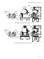
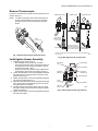
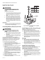
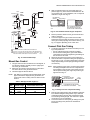
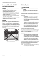
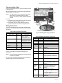
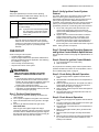
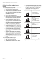
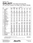
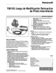
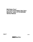
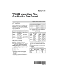
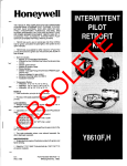
Y8610U Intermittent Pilot Retrofit Kit
PRODUCT DATA
—
—
—
—
—
—
—
392431 Igniter-Sensor
394800-30 Ignition Cable
393691 Natural to LP Gas Conversion Kit
Wiring Harness
393690-14 Straight Flange Kit (3/4 in.)
Reducer adapters for gas control with VR8304M
Installation hardware
Temperature Ratings:
— S8610U: -40°F to 165°F (-40°C to 74°C)
— VR8304M: -40°F to 175°F (-40°C to 79°C)
— VR8204A: 0°F to 175° F (-18°C to 79°C)
GENERAL
The Y8610U is a complete kit for converting conventional
standing pilot systems to intermittent pilot systems. It is used
on gas-fired atmospheric furnaces, boilers, and heating
appliances. Not for use on direct vent, induced draft, or power
burner equipment. Meets ANSI Z21.71 standard for automatic
intermittent pilot ignition systems on central furnaces and
boilers.
FEATURES
• Y8610U kits can be used with either natural or LP gas.
• The S8610U ignition control provides a 90 second
maximum ignition trial, shuts off, waits five minutes
nominal, then re-initiates the pilot ignition sequence. The
ignition trial, shutoff, and wait cycle repeat until the pilot
lights or the call for heat ends.
Each kit includes:
— S8610U Intermittent Pilot Module
— VR8304M Dual Valve Combination Gas Control
or
VR8204A Dual Valve Combination Gas Control
®
Intermittent Pilot Gas Ignition Control Module
• Uses flame rectification for flame sense
• Internal spark generator lights pilot gas; main burner lights
after pilot flame lights and proves
• 100% shutoff of pilot and main gas if burner fails to light
• Continuous retry ignition sequence prevents nuisance
lockouts
• Two LEDs indicate system status and flame signal strength
Gas Control Valve
• Straight through body pattern
• VR8304M capacity is 270 ft3/hr (7.6 m3/hr)
• VR8204A capacity with or without 1/2” x 3/4” adapter is
150 ft3/hr (4.2 m3/hr)
• Manual ON-OFF valve blocks gas flow into the gas control
when in the OFF position
• Two main automatic valves: one solenoid-operated, and
one a servo-operated diaphragm system
Igniter-Sensor
• Single electrode made of Kanthal provides both ignition
and flame sensing
• Rated for 1775°F (968°C) at electrode tip; 1250°F (677°C)
at ceramic insulator
Contents
General .............................................................................1
Specifications ...................................................................2
Planning the Installation ....................................................6
Installation ........................................................................7
Settings ............................................................................14
Checkout ..........................................................................15
Operation ..........................................................................16
Troubleshooting ................................................................17
Ansi Standards .................................................................22
Automatic Ignition Systems
ANSI Z21.20
Put UPC Code Here
68-0291-03
Y8610U INTERMITTENT PILOT RETROFIT KIT
Table 1. S8610U Universal Intermittent Pilot Gas Ignition Control Module.
IgniterSensor
Type
Valve
Current
Rating
@ 24 Vac
Combination 1.0 A Pilot
and
(one rod;
2.0 A Main
local flame
sensing)
Prepurge
Trial for
Ignition
Timing
Pilot Ignition Sequence
(field selectable) (field selectable)
Type
0 (zero) or 30
seconds;
15 or 90
seconds;
Retry
0 (zero) seconds 90 seconds
recommended recommended
SPECIFICATIONS
Ignition Sequence
(After prepurge,
if prepurge is selected)
Integral
Damper
Connector
Spark and pilot gas ON until
lightoff or trial for ignition ends.
Included for use
as needed.
If established flame is lost, trial
for ignition restarts immediately.
If pilot fails to light, pilot gas and
spark turned off (100% shutoff).
After 5 minute delay, a new trial
for ignition is initiated.
This sequence continues until
lightoff or “Call for Heat” is
removed.
If initially installed
and powered up
with damper
attached, unit
must always have
a vent damper
connected.
S8610U Intermittent Pilot Gas
Ignition Control Specifications
IMPORTANT
The specifications given in this publication do not
include normal manufacturing tolerances. Therefore,
units might not match the listed specifications
exactly. Also, units are tested and calibrated under
closely controlled conditions, and some minor differences in performance can be expected if those conditions are changed.
Control Voltage: Line 24 Vac (18-30 Vac) 50/60 Hz
Trial for Ignition: See Table 1 above
Prepurge: See Table 1 above
Flame Failure Response Time: 2 seconds maximum
LEDs:
The green LED provides system status, error codes and
indicates flame sensing
Y8610U Intermittent Pilot Retrofit Kit
Electrical Ratings:
Operating Temperature:
Minimum ambient temperature rating is -40°F (-40°C)
• Voltage and Frequency: 24 Vac, 60 Hz
• Current Rating: 0.7A (includes both module and gas
control)
• Thermostat Anticipator Setting: 0.7A plus current ratings of
other devices in the thermostat control circuit
Maximum ambient temperature rating when used with
2.0 A main valve is 165°F (74°C)
Relative Humidity: 0% to 95% non condensing
Dimensions: See Fig. 2 on page 4.
Thermostat Compatibility:
Compatible with any Honeywell 24V thermostat and with
competitive 24V thermostats that are powered independently of the module.
ORDERING INFORMATION
When purchasing replacement and modernization products from your TRADELINE® wholesaler or distributor, refer to the
TRADELINE® Catalog or price sheets for complete ordering number.
If you have additional questions, need further information, or would like to comment on our products or services, please write or
phone:
1. Your local Honeywell Automation and Control Products Sales Office (check white pages of your phone directory).
2. Honeywell Customer Care
1885 Douglas Drive North
Minneapolis, Minnesota 55422-4386
3. http://customer.honeywell.com or http://customer.honeywell.ca
In Canada—Honeywell Limited/Honeywell Limitée, 35 Dynamic Drive, Toronto, Ontario M1V 4Z9.
International Sales and Service Offices in all principal cities of the world. Manufacturing in Australia, Canada, Finland, France,
Germany, Japan, Mexico, Netherlands, Spain, Taiwan, United Kingdom, U.S.A.
68-0291—03
2
Y8610U INTERMITTENT PILOT RETROFIT KIT
Wiring Connections:
— Between the module and gas control: 30 in. (762 mm)
wiring harness with 1/4 in. quick-connect terminals.
— Between the module and the igniter-sensor: 30 in.
(762 mm) ignition cable with stud terminal and 1/4 in.
quick-connect terminal.
Transformer Sizing:
Add current ratings of Y8610, vent damper, and any other
control system components. Multiply this total by 24V to
determine the transformer VA requirement.
Mounting:
Mounts in any position except with terminals up. Recommended mounting position is with terminals down to provide
maximum protection from dripping water or dust accumulation. Refer to Fig. 14 on page 12.
Terminals:
1/4 in. male quick-connects. S8610U has Molex plug for
connection to a vent damper harness. Once the S8610U
has powered a vent damper, the module works only if the
vent damper is connected.
Fasten with No. 6-32 machine screws or No. 8 sheet metal
screws or 8-18 x 5/8 pan head tapping screws of appropriate length.
VR8204A and VR8304M Dual Valve
Combination Gas Controls
Specifications
Table 2. VR8204A and VR8304M Dual Valve Combination Gas Controls Specifications.
Capacitya
Model
Pipe Size
Ambient Temperature Rating
Dimensions
VR8204A
150
(4.2
(with or
without 1/2” x 3/4” adapter)
1/2 in. X. 1/2 in. NPT
inlet x outletb
0° to 175° F (-18° to 79° C)
See Fig. 4 on page 5
VR8304M
270 ft3/hr (7.6 m3/hr)
1/2 in. X. 3/4 in. NPT
inlet x outlet
-40° to 175°F (-40° to 79°C)
See Fig. 3 on page 5
ft3/hr
m3/hr);
on 1,000 Btu/ft3, 0.64 specific gravity natural gas at 1 in. wc pressure drop (37.3 MJ/m3, 0.64 specific gravity natural gas at
0.25 kPa pressure drop).
b
3/4 in. straight flange included to provide 3/4” NPT outlet if needed.
a Based
Igniter-Sensor Specifications
Mounting:
Can be mounted from 0 to 90 degrees, in any direction,
from the gas control upright position
Model:
392431 Igniter-Sensor; includes igniter-sensor assembly,
ground rod, and adapter (refer to Fig. 1 on page 4)
Pressure Rating: 1/2 psig (3.45 kPa) inlet pressure
Terminals: 1/4 in. male quick-connect terminals
Electrode/Flame Rod Material: Kanthal
Maximum Temperature Ratings:
Ground Rod Tip: 1775°F (968°C)
Ceramic Insulator: 1250°F (677°C)
Dimensions: See Fig. 5 on page 6.
Mounting:
Attach the supplied ground rod and adapter, which replace
the thermocouple on the existing pilot burner
3
68-0291—03
Y8610U INTERMITTENT PILOT RETROFIT KIT
VR8304
S8610U INTERMITTENT
PILOT MODULE WITH
WIRING HARNESS
392431 IGNITERSENSOR ASSEMBLY
GROUND
ROD
ALSO INCLUDED:
IGNITER-SENSOR
• 394800-30 IGNITION CABLE (30 IN. (760 mm))
• 393690-14 STRAIGHT FLANGE KIT
• 393691 NATURAL GAS TO LP CONVERSION KIT
• REDUCER ADAPTERS FOR GAS CONTROL (WITH VR8304M)
• SCREWS
ADAPTER
M32519
• WIRE NUTS (3)
Fig. 1. Y8610U retrofit kit components.
3/16 (5) x 2
3 3/16
(81)
3 7/8
(98) 3 3/8
(86)
2 (51)
1 1/32
(26)
3 3/8 (86) x 2
3/16
(5) x 2
5 1/2 (140)
M32363
Fig. 2. S8610U module dimensions in inches (mm).
68-0291—03
4
Y8610U INTERMITTENT PILOT RETROFIT KIT
4 IN. (102) MAX
SWING RADIUS
1/4 INCH
QUICK-CONNECT
TERMINALS
PRESSURE REGULATOR
ADJUSTMENT
(UNDER CAP SCREW)
INLET
PRESSURE TAP
INLET
3-15/16
(99)
WIRING
TERMINALS (3)
OUTLET
PRESSURE
TAP
1/2
1 (13)
(25)
OUTLET
1-7/16
(36)
PILOT OUTLET
PILOT ADJUSTMENT
GAS
CONTROL (UNDER CAP SCREW)
KNOB
1/2
(13)
4-1/16 (104)
M24885
1 (25)
2-11/16 (69)
M24886
Fig. 3. VR8304M mounting dimensions in inches (mm).
3 5/8 (91) MAX
SWING RADIUS
PRESSURE REGULATOR
ADJUSTMENT
(UNDER CAP SCREW)
INLET
PRESSURE TAP
INLET
1/4 INCH
QUICK-CONNECT
TERMINALS
PV
PV/MV
MV
WIRING
TERMINALS (3)
OUTLET
PRESSURE
TAP
3-1/2
(89)
1/2
1 (13)
(25)
OUTLET
1-7/16
(36)
PILOT OUTLET
PILOT ADJUSTMENT
GAS
CONTROL (UNDER CAP SCREW)
KNOB
M24887
4-1/8 (108)
1/2
(13)
1 (25)
2-11/16 (69)
M24888
Fig. 4. VR8204A mounting dimensions in inches (mm).
5
68-0291—03
Y8610U INTERMITTENT PILOT RETROFIT KIT
Frequent Cycling
1-1/8 (29)
These controls are designed for use on appliances that
typically cycle three to four times an hour only during the
heating season. In year-round applications with greater cycling
rates, the control module can wear out more quickly; perform a
monthly checkout.
Water or Steam Cleaning
2-3/8
(60)
If the control module gets wet, replace it. If the appliance is
likely to be cleaned with water or steam, protect (cover) the
controls and wiring from water or steam flow. Mount the
controls high enough above the bottom of the cabinet so they
do not get wet during normal cleaning procedures. Use a
NEMA 4 enclosure for the ignition control module.
3-1/2
(89)
High Humidity or Dripping Water
M6860
Dripping water can cause the control module and the gas
control to fail. Never install an appliance where water can drip
on the controls.
Fig. 5. 392431 Igniter-sensor mounting dimensions in
inches. (mm).
In addition, high ambient humidity can cause the control
module and the gas control to corrode and fail.
PLANNING THE INSTALLATION
If the appliance is in a humid atmosphere, make sure air
circulation around the controls is adequate to prevent
condensation. Also, regularly check out the system. A NEMA 4
enclosure is recommended for the ignition control module.
WARNING
Fire or Explosion Hazard.
Can cause severe injury, death or property damage.
1. Plan the installation as outlined below.
2. Plan for frequent maintenance as described in the
Maintenance section.
Corrosive Chemicals
Corrosive chemicals can attack the ignition control module and
gas control, eventually causing a failure. If chemicals are used
for routine cleaning, make sure they do not reach the controls.
Where chemicals are suspended in air, as in some industrial or
agricultural applications, use a NEMA 4 enclosure for the
ignition control module.
Intermittent pilot systems are used on a wide variety of central
heating equipment and on heating appliances such as
commercial cookers, agricultural equipment, industrial heating
equipment and pool heaters. Some of these applications may
make heavy demands on the controls, either because of
frequent cycling, or because of moisture, corrosive chemicals,
dust or excessive heat in the environment. In these situations,
special steps may be required to prevent nuisance shutdowns
and premature control module failure. These applications
require special Honeywell review; contact your Honeywell
Sales Representative for assistance.
Dust or Grease Accumulation
Heavy accumulations of dust or grease can cause controls to
malfunction. Where dust or grease can be a problem, provide
covers for the ignition control module and the gas control to
limit contamination. A NEMA 4 enclosure is recommended for
the ignition control module.
Heat
Review the following conditions that can apply to your specific
installation and take the precautionary steps suggested.
68-0291—03
Excessively high temperatures can damage controls. Make
sure the maximum ambient temperature at the control module
does not exceed the rating of the control module. If the
appliance operates at very high temperatures, use insulation,
shielding, and air circulation, as necessary, to protect the
controls. Proper insulation or shielding should be provided by
the appliance manufacturer; verify proper air circulation is
maintained when the appliance is installed.
6
Y8610U INTERMITTENT PILOT RETROFIT KIT
INSTALLATION
• Exposure to water, dirt, chemicals, and heat can damage
the ignition control module or the gas control and shut down
the control system. A NEMA 4 enclosure can reduce
exposure to environmental contaminants.
When Installing this Product…
1.
2.
3.
4.
Read these instructions carefully. Failure to follow them
could damage the product or cause a hazardous condition.
Check the ratings given in these instructions and on the
product to ensure the product is suitable for your application.
Installer must be a trained, experienced service technician.
After completing installation, use these instructions to
check product operation.
The maintenance program should include regular checkout of
the system as outlined under “Checkout” on page 15.
WARNING
FIRE OR EXPLOSION HAZARDCAN CAUSE
PROPERTY DAMAGE, SEVERE INJURY, OR
DEATH.
Do not attempt to disassemble or clean the module.
Improper reassembly and cleaning can cause
unreliable operation.
IMPORTANT
1. Installer must comply with local codes and ordinances
of the National Fuel Code (ANSI Z223.1—NFPA
No. 54) and National Electrical Code (ANSI NFPA
No. 70).
2. Installer must fill in and attach label to appliance being
converted.
3. Use Y8610 Retrofit Kit only with atmospheric burners.
Do not use on direct vent appliances, appliances with
induced draft, or power burners.
4. Do not use the Y8610 Retrofit Kit with mercury pilots
or 250 to 750 mV pilot systems.
Maintenance frequency must be determined individually for
each application based on:
• Cycling frequency: Appliances that cycle more than 20,000
times annually should be checked monthly.
• Intermittent use: Appliances that are used seasonally
should be checked before shutdown and again before the
next use.
• Consequence of unexpected shutdown: Where the cost of
an unexpected shutdown is high, the system should be
checked more often.
• Dusty, wet, or corrosive environment: Because these
environments can cause the controls to deteriorate more
rapidly, the system should be checked more often.
WARNING
FIRE OR EXPLOSION OR ELECTRICAL SHOCK
HAZARD CAN CAUSE PROPERTY
DAMAGE,SEVERE INJURY, OR DEATH.
Follow these warnings exactly:
1.
2.
3.
4.
Any ignition control module or gas control should be replaced if
it does not perform properly on checkout or troubleshooting. In
addition, replace any ignition control module or gas control if it
is wet or looks like it has ever been wet. Protective enclosures
as outlined under “Planning the Installation” on page 6 are
recommended regardless of checkout frequency.
Disconnect the power supply before wiring to
prevent electrical shock or equipment damage.
To avoid dangerous accumulation of fuel gas, turn
off gas supply at the appliance service valve
before starting Installation and perform the Gas
Leak Test immediately following the installation.
(See “Checkout” on page 15.)
Never install where water can flood, drip, or
condense on module or gas control. Never use a
module or gas control that has been wet. If wet,
controls can malfunction and lead to an
accumulation of explosive gas.
Do not light or operate electric switches, lights, or
appliances until you are sure the appliance area is
free of gas. Liquefied petroleum (LP) gas is
heavier than air and does not vent upward
naturally.
Perform the Pre installation Safety
Inspection
The pre-installation checks described below must be
completed before the Y8610U Intermittent Pilot Retrofit Kit is
installed. If a condition that could result in unsafe operation is
detected, the appliance should be shut off and the owner
advised of the unsafe condition. Correct any potentially unsafe
condition before proceeding with the installation. See “Exhibit
A” on page 22.
The following safety checklist should be followed in making the
safety inspection:
1.
Maintenance Requirements in Severe
Environments
2.
Regular preventive maintenance is important in any
application, but especially so in commercial cooking,
agricultural, and industrial applications because:
3.
• In many such applications, particularly commercial cooking,
the equipment operates 100,000-200,000 cycles per year.
Such heavy cycling can wear out the gas control in one to
two years. A normal forced air furnace, for which the
controls were originally intended, typically operates less
than 20,000 cycles per year.
4.
7
Conduct a Gas Leakage Test of the appliance piping and
control system downstream of the shut-off valve in the
supply line to the appliance.
Visually inspect the venting system for proper size and
horizontal pitch and determine there is no blockage or
restrictions, leakage or corrosion or other deficiencies
which could cause an unsafe condition.
Shut off all gas to the appliance and shut off any other
fuel-burning appliance within the same room. Use the
shutoff valve in the supply line to each appliance. If a
manual gas valve is not in the gas supply line within 6
feet of the appliance in an accessible location, one shall
be installed.
Inspect burners and crossovers for blockage and corrosion.
68-0291—03
Y8610U INTERMITTENT PILOT RETROFIT KIT
5.
6.
7.
8.
9.
10.
11.
12.
13.
14.
Shut Down Appliance
Applicable only to warm air heating appliances. Inspect
heat exchangers for cracks, openings or excessive corrosion.
Applicable only to boilers. Inspect for evidence of water
or combustion product leaks.
Insofar as is practical, close all building doors and windows and all doors between the space in which the appliance is located and other spaces of the building. Turn on
clothes dryers. Turn on any exhaust fans, such as range
hoods and bathroom exhausts, so they will operate at
maximum speed. Do not operate a summer exhaust fan.
Close fireplace dampers. If, after completing steps 7
through 12, it is believed sufficient combustion air is not
available, refer to 1.3.4 of the National Fuel Gas Code
(Z223.1) for guidance.
Place in operation the appliance being inspected. Follow
the lighting instructions. Adjust thermostat so appliance
will operate continuously.
Determine the following:
a. Determine that the pilot is burning properly and that
main burner ignition is satisfactory by interrupting
and re-establishing the electrical supply to the appliance in any convenient manner.
b. Determine manifold pressure in order to match input
after the new control is installed.
Perform the following tests:
a. Visually determine that main burner gas is burning
properly; i.e., no floating, lifting or flashback. Adjust
the primary air shutter(s) as required.
b. If appliance is equipped with high and low flame control or flame modulation, check for proper main
burner operation at low flame.
Test for spillage at the draft hood relief opening after 5
minutes of main burner operation. Use a draft gauge, the
flame of a match or candle, or smoke from a cigarette,
cigar or pipe.
Return doors, windows, exhaust fans, fireplace dampers
and all other fuel-burning appliances to their previous
conditions of use.
Applicable only to warm air heating appliances. Check
both limit controller and fan controller for proper operation. Limit controller operation can be checked by temporarily disconnecting the electrical supply to the blower
motor and determining that the limit control acts to shut
off the main burner gas.
Applicable only to boilers:
a. Determine that the circulating water pumps are in
operating condition.
b. Test low water cutoffs, automatic feed controls, pressure and temperature limit controls and relief valves
in accordance with the manufacturer’s recommendations and instructions to determine they are in operating condition.
1.
2.
Check Appliance Wiring
The existing standing pilot gas control wires are used to control
Y8610U Retrofit Kit. Carefully identify and tag the wires before
disconnecting. See Fig. 6 for the most common types of
terminal arrangements.
TO
TRANSFORMER
TO
THERMOSTAT
COMMON
TO
TRANSFORMER
TO
THERMOSTAT
COMMON
TO
TRANSFORMER
TO
THERMOSTAT
M6858
Fig. 6. Wiring connections on standing pilot gas controls.
Remove Standing Pilot Gas Control
1.
2.
If the gas control has a common terminal(s), remove the
wires connected to the common terminal(s) and splice
together with one of the wire nuts provided.
Label and remove the remaining wires.
WARNING
FIRE OR EXPLOSION HAZARDCAN CAUSE
PROPERTY DAMAGE, SEVERE INJURY, OR
DEATH.
Do not bend the pilot gas tubing at the gas control or at
the pilot burner to prevent gas leakage at the
connection.
3.
4.
5.
6.
68-0291—03
Turn off the gas supply at the appliance service valve.
Do not use the gas control knob.
Turn off the electricity at the service entrance.
8
Disconnect the pilot tubing at the gas control. Cut off and
discard the compression fitting. Do not disturb the compression fitting or pilot tubing at the pilot burner.
Disconnect the thermocouple lead at the gas control.
Disconnect the gas piping at the gas control.
Discard the gas control.
Y8610U INTERMITTENT PILOT RETROFIT KIT
Remove Thermocouple
Unscrew or snap the thermocouple out of the pilot burner and
discard. See Fig. 7.
SCREW-IN TYPE
CLAMP TYPE
PUSH-IN TYPE
NOTE: It could be necessary to pull out the main burner for
access to the pilot burner. Do not move or relocate
the pilot burner. Do not bend tubing near the pilot
burner.
PILOT
BURNER
ADD ADAPTER,
INSERT GROUND
ROD IN PILOT
REMOVE
THERMOCOUPLE
PILOT
TUBING
TIGHTEN NUT
M6862
M24902
Fig. 8. Mount ground rod on pilot burner.
Install Igniter-Sensor Assembly
2.
3.
4.
5.
6.
INSERT
GROUND ROD
BE SURE THE GROUND CLIP IS SNAPPED ONTO THE PILOT BURNER OR
ITS GAS LINE.
Fig. 7. Remove thermocouple from pilot burner.
1.
SLIP NUT OFF ADAPTER
AND CLAMP GROUND ROD
IN PILOT WITH SHOULDER
ABOVE CLAMP AS SHOWN
Install the ground rod. See Fig. 8.
• Mount adapter to the ground rod, if needed.
• Insert the ground rod in place of the thermocouple on
the pilot burner. Push the ground rod all the way up
and fasten as shown in Fig. 8.
• Align the ground rod so the clip hugs the pilot burner
and keeps the ground rod from rotating. See Fig. 9.
Loosen the setscrews on the mounting bracket and slide
the igniter-sensor mounting bracket over the top of the
ground rod. See Fig. 9.
Tighten the setscrews on the mounting bracket using the
hex wrench provided. See Fig. 9.
Adjust the electrode position so the electrode tip and gap
are in the pilot flame. Push/pull the ground rod to move
the igniter-sensor up and down.
Check that the chosen position allows room to connect
the ignition cable to the stud terminal. Rotate the ignitersensor as necessary.
Tighten the setscrews on the mounting bracket using the
hex wrench provided.
GROUND ROD
ELECTRODE
GAP
ELECTRODE
ELECTRODE
SETSCREW (2)
MOUNTING
BRACKET
IGNITER-SENSOR
PILOT
BURNER
GROUND
ROD CLIP
STUD TERMINAL
PILOT GAS
TUBING
M6863A
Fig. 9. Fasten igniter-sensor to ground rod.
9
68-0291—03
Y8610U INTERMITTENT PILOT RETROFIT KIT
Install the Gas Control
COLOR CODE FOR
LP
NATURAL
GAS
GAS
WARNING
CAP SCREW
FIRE OR EXPLOSION HAZARDCAN CAUSE
PROPERTY DAMAGE, SEVERE INJURY, OR
DEATH.
Follow these warnings exactly:
1.
2.
3.
SILVER
WHITE
SPRING
STAINLESS
STEEL
RED
Do not bend the pilot gas tubing at the gas control
or at the pilot burner after the compression fitting is
tightened. Gas leakage at the connection can
result.
Always install a sediment trap in the gas supply
line to prevent contamination of the gas control.
Do not force the gas control knob. Use only your
hand to turn the gas control knob. If the gas control
knob does not operate by hand, the gas control
should be replaced by a qualified service technician. Force or attempted repair can result in a fire
or explosion.
PRESSURE
REGULATOR
HOUSING
IMPORTANT
These gas controls are shipped with protective seals
over the inlet and outlet tappings. Do not remove the
seals until ready to connect the piping.
M8083A
Fig. 10. Installation of conversion kit in regulated
gas control.
Converting Between Natural and LP Gas
Install Adapters to Gas Control (if used)
WARNING
393690-14 Straight Flange (3/4 in.)
FIRE OR EXPLOSION HAZARDCAN CAUSE
PROPERTY DAMAGE, SEVERE INJURY, OR
DEATH.
1.
Do not attempt to use a gas control set for natural
gas on LP gas or a gas control set for LP gas on
natural gas.
2.
When making a conversion, main and pilot burner
orifices must be changed to meet appliance manufacturer specifications.
To convert from natural gas to LP, use the 393691 LP
Conversion Kit that is included with the Y8610U Intermittent
Pilot Retrofit Kit. To convert from LP to natural gas, use the
394588 Natural Gas Conversion Kit (ordered separately).
Step-opening gas controls cannot be converted.
1.
2.
3.
4.
Remove the seal over the gas control inlet or outlet.
Make sure that the O-ring is fitted in the flange groove. If
the O-ring is not attached or is missing, do not use the
flange.
With the O-ring facing the gas control, align the gas control threaded holes with the flange clearance holes.
Insert and tighten the screws provided with the flange.
Tighten the screws to 25 inch pounds of torque to provide a gas tight seal.
Bushings
1.
2.
To convert control from one gas to another:
1. Turn off the main gas supply to the appliance.
2. Remove the regulator cap screw and pressure regulator
adjusting screw. See Fig. 3 or Fig. 4 on page 5.
3. Remove the existing spring.
4. Insert the replacement spring with the tapered end down.
See Fig. 10.
5. Install the new plastic pressure regulator adjustment
screw so that the top of the screw is flush (level) with the
top of the regulator. Turn the pressure regulator adjustment screw clockwise six complete turns. This provides
a preliminary pressure setting of about 10.0 in. wc (2.5
kPa) for LP regulator and 3.5 in. wc (0.9 kPa) for natural
gas regulator.
6. Check the regulator setting either with a manometer or
by clocking the gas meter. See “Checkout” on page 15.
7. Install the new cap screw.
8. Mount the conversion label on the control.
9. Install the control and appliance according to the appliance manufacturer instructions.
68-0291—03
BLACK
PRESSURE
REGULATOR WHITE
ADJUSTING
SCREW
3.
Remove the seal over the gas control inlet or outlet.
Apply a moderate amount of good quality pipe compound to the bushing, leaving the two end threads bare.
For an LP installation, use a compound resistant to LP
gas. Do not use Teflon tape.
Insert the bushing in the gas control and thread the pipe
carefully into the bushing until tight.
Install Gas Control Piping
All pipe must comply with local codes and ordinances or with
the National Fuel Code (ANSI Z223.1 NFPA No. 54),
whichever applies. Tubing installation must comply with
approved standards and practices.
1. Use new, properly reamed pipe free from chips. If tubing
is used, ensure that ends are square, deburred, and
clean. All tubing bends must be smooth and without
deformation.
2. Run the new pipe or tubing to the gas control. When tubing is used, obtain a tube-to-pipe coupling to connect the
tubing to the gas control.
3. Install a sediment trap in the gas supply line. See Fig. 11
on page 11.
10
Y8610U INTERMITTENT PILOT RETROFIT KIT
4.
DROP
PIPED
GAS
SUPPLY
HORIZONTAL
GAS
CONTROL
TWO IMPERFECT
GAS CONTROL
THREADS
RISER
GAS
CONTROL
Apply a moderate amount of good quality pipe compound to pipe only; leave the two end threads bare. Do
not use teflon tape. In LP installations, use a compound
resistant to LP gas. See Fig. 12.
PIPED
GAS
SUPPLY
3 IN.
(76 MM)
MINIMUM
PIPE
THREAD PIPE CORRECT LENGTH
2
M3312
APPLY A MODERATE AMOUNT OF
PIPE COMPOUND TO PIPE ONLY
(LEAVE TWO END THREADS BARE).
DROP
HORIZONTAL
1
Fig. 12. Use moderate amount of pipe compound.
3 IN.
(76 MM)
MINIMUM
TUBING
GAS
SUPPLY
5.
2
6.
GAS
CONTROL
RISER
3 IN.
(76 MM)
MINIMUM
Connect Pilot Gas Tubing
2
1.
ALL BENDS IN METALLIC TUBING SHOULD BE SMOOTH.
1
2 CAUTION: SHUT OFF THE MAIN GAS SUPPLY BEFORE REMOVING
END CAP TO PREVENT GAS FROM FILLING THE WORK AREA. TEST
FOR GAS LEAKAGE WHEN INSTALLATION IS COMPLETE.
M3077A
2.
3.
Fig. 11. Install sediment trap.
Mount Gas Control
1.
2.
3.
Remove protective seals over the gas control inlet and
outlet, if necessary.
Connect the pipe to the gas control inlet and outlet.
Tighten the inlet and outlet connections using a wrench
on the gas control projecting wrench boss. See Fig. 3 or
Fig. 4 on page 5 depending on the valve used.
The gas control can be mounted from 0 to 90 degrees, in
any direction including vertically, from the upright position of the gas control knob.
Mount the gas control so the gas flow is in same direction as the arrow on the gas control bottom.
Thread the pipe as listed in Table 3.
Cut the pilot gas tubing and bend as necessary for routing to the pilot burner.
• Do not make sharp bends or deform the tubing.
• Do not bend the tubing at the gas control after the
compression nut has been tightened; gas leakage at
the connection can result.
Square off and remove the burrs from the tubing end.
Unscrew the brass compression fitting from pilot gas outlet (see Fig. 3 or Fig. 4 on page 5 depending on the valve
used). Slip the fitting over the pilot gas tubing and slide
out of the way.
NOTE: When replacing a gas control, cut off the old compression fitting and replace with the new compression fitting provided on the new gas control. Never use the
old compression fitting as it might not provide a gas
tight seal. See Fig. 13.
NOTE: See Table 3 for maximum pipe threading depth. If the
pipe is inserted too deeply into the gas control, the
second main valve or safety valve can distort or malfunction.
GAS CONTROL
TIGHTEN NUT ONE TURN
BEYOND FINGER TIGHT
PILOT
TUBING
Table 3. NPT pipe thread length (in.)
Pipe
Size
Overall
Thread Length
Maximum Depth Pipe Can Be
Inserted Into Gas Control
3/8
9/16
3/8
1/2
3/4
1/2
3/4
13/16
3/4
FITTING BREAKS OFF AND CLINCHES
TUBING AS NUT IS TIGHTENED
M6868A
Fig. 13. Always use new compression fitting.
4.
5.
11
Push pilot gas tubing into the pilot gas tapping until it bottoms. While holding the tubing all the way in, slide the
compression fitting into place and engage the threads.
Turn the fitting until finger tight. Use a wrench to tighten
one more turn. Do not overtighten.
Connect the other end of the pilot gas tubing to the pilot
burner according to the pilot burner manufacturer
instructions.
68-0291—03
Y8610U INTERMITTENT PILOT RETROFIT KIT
Locate and Mount the S8610U
Intermittent Pilot Module
Wire the System
CAUTION
Location
ELECTRICAL SHOCK OR EQUIPMENT DAMAGE
HAZARD.
Disconnect the power supply before making wiring
connections to prevent electrical shock or equipment
damage.
Identify a mounting location for the S8610U ignition control.
The mounting location must provide:
— Good, clear access to the field wiring terminals.
— Operating ambient temperatures between
-40°F (-40°C) and 165°F (74°C).
— Direct the cable route to the pilot burner. The cable route
must be 30 inches (762 mm) or less and not expose the
cable to excessive heat.
— Relative humidity below 95% non condensing.
— Protection from water, steam or corrosive chemicals that
are used to clean the appliance.
— Protection from dripping water, such as from an overfilled
humidifier or from condensation.
— Protection from dust or grease accumulation.
All wiring must comply with local codes and ordinances. Refer
to Fig. 15 and Table 5 on page 13 for typical connections.
IMPORTANT
1. As shown in the wiring diagrams, a common ground
is required on:
The pilot burner mounting bracket, and the GND
(BURNER) terminal on the ignition control module.
Failure to use the GND (BURNER) terminal may
result in intermittent loss of spark and/or loss of flame
current sensitivity.
2. Make sure the transformer has adequate VA. The
ignition control module requires at least 0.1 A at 24
Vac. Add the current draws of all other devices in the
control circuit, including the pilot and main valves in
the gas control, and multiply by 24 to determine the
total VA requirement of these components. Add this
total to 2.4 VA (for the ignition control module). The
result is the minimum transformer VA rating. Use a
Class II transformer if replacement is required.
Mounting
Mount the ignition control module with the terminals down to
protect them from dripping water and dust. The control module
can also be mounted with the terminals on either side. Do not
mount with the terminals pointing up. Fig. 14 illustrates the
incorrect mounting position. Use the S8610U as a template to
mark the mounting hole pattern. Drill new holes, as required.
Fasten securely with four – No. 6-32 machine screws, or No. 8
sheet metal screws, or 8-18 x 5/8 Pan Head tapping screws.
IMPORTANT
Do not mount with terminals facing up.
Connect Vent Damper (Optional)
If the ignition control module is to be used with an existing vent
damper and harness to be connected to the module’s integral
damper connector in an atmospheric appliance, perform the
following to connect it to the module:
IMPORTANT
After the initial power-up, the ignition control module
senses the presence of the vent damper connection.
If the vent damper is connected, the ignition control
module permanently configures itself to operate only
with the damper connected.
Once an ignition control module powers up with a
vent damper connected, the module will not function
without a vent damper being connected.
M29889
Using the wiring harness on the appliance, insert the matching
6-pin plug into the connector labeled P1 (see Fig. 15 on
page 13) on the S8610U ignition control module and connect
the other end to the vent damper.
Fig. 14. Incorrect mounting.
NOTE: The connector (P1) accepts a Molex 03-06-2061 plug
on the existing vent damper harness.
68-0291—03
12
Y8610U INTERMITTENT PILOT RETROFIT KIT
Connect Ignition Cable
Use the provided ignition cable to connect the S8610U module
to the pilot burner.
Be sure the ignition cable is not exposed to high temperature
while the appliance is operating.
SPARK
NOTE: The cable must not run in continuous contact with a
metal surface or spark voltage may be greatly
reduced. Use ceramic or plastic standoff insulators as
required.
To install:
1. Connect one end of the cable to the male quick connect
SPARK terminal on the ignition module.
2. Connect the other end of the cable to the igniter or
igniter-sensor stud on the pilot burner/igniter-sensor.
P1 VENT DAMPER
CONNECTOR
Table 4. Wiring Harness Connections.
Black / 25 VAC
Orange / 25 VAC-GND
TH-W
SENSE
JUMPER
WIRE
24V GND
Connect the provided harness to the ignition module and the
gas control. The harness ends are labeled for easy installation.
See Table 4.
S8610U
Terminal
REMOTE
SENSE
PV
BRN/GND
Wiring Connections
Harness Wire Color
/ Wire Label
TH-W (OPT.)
24V (OPT.)
MV
MV/PV
Gas Control Terminal
/ Tstat Load
Fig. 15. S8610U Typical wiring connections.
Thermostat call for
heat to original
standing pilot valve
Table 5. S8610U Typical Wiring Connections.
Connector
Label
24V (GND) Transformer 24 VAC
ground lead to original
standing pilot valve
Red / MV
MV
MV
White / MV-PV
MV-PV
MV-PV
Blue / PV
PV
PV
Green / GND
GND
Ground terminal on
gas control
M29890
Size or
Type
1/4 inch
MV/PV
1/4 inch
Common terminal for gas valves
PV
1/4 inch
Pilot Valve connection
BRN GND 1/4 inch
Use Fig. 15 and Table 5 to make the remaining wiring
connections.
NOTE: The 24V terminal on the S8610U is used only when a
vent damper is installed.
Fig. 16 on page 14 illustrates the typical wiring connections in
a heating system with an atmospheric burner.
13
Description
MV
Main Valve connection
Burner Ground
24V GND
1/4 inch
Return path to transformer
24V
1/4 inch
Optional—
24 Vac power connection for Vent
Damper
TH-W
1/4 inch
Connector for “Call for Heat” signal
from thermostat
P1
6-pin
keyed plug
Connector for Vent Damper
connection (used to control a
connected damper in atmospheric
appliances)
Flame
Current
Two holes
Micro-ammeter connector
P4
(Jumper)
Jumper
Provides a lockout for the DIP
switch settings (See “Jumper” on
page 15.)
SENSE
JUMPER
WIRE
Wire with
3/16 inch
quick
connect
Connects to the REMOTE SENSE
connector for installations with a
single spark rod (local flame
sensing)
REMOTE
SENSE
3/16 inch
Flame Sensor connector
SPARK
1/4 inch
For single rod installations, connect
the SENSE JUMPER WIRE to this
terminal connector.
High voltage sparking electrode
connection
68-0291—03
Y8610U INTERMITTENT PILOT RETROFIT KIT
S8610U
MV
GND 24V
MV/
PV PV (BRN) GND 24V TH-W
REMOTE
SENSE
5
P1
SPARK
6
VR8204
COMBINATION
GAS CONTROL
3
JUMPER
WIRE
PV
PV/MV
THERMOSTAT
MV
2
LIMIT
CONTROLLER
4
PILOT
BURNER/
IGNITER
1
L1 (HOT)
L2
PILOT BURNER
GROUND
PILOT GAS
SUPPLY
1 POWER SUPPLY. PROVIDE DISCONNECT MEANS AND OVERLOAD PROTECTION AS REQUIRED.
2 ALTERNATE LIMIT CONTROLLER LOCATION.
3 MAXIMUM CABLE LENGTH 3 FT. [0.9 M].
4 CONTROLS IN 24V CIRCUIT MUST NOT BE IN GROUND LEG TO TRANSFORMER.
5 LEAVE VENT DAMPER PLUG (P1) UNCONNECTED.
6 CONNECT JUMPER WIRE TO THE REMOTE SENSE CONNECTOR.
M32356
Fig. 16. Y8610U connections in a heating system with an atmospheric burner and no vent damper.
SETTINGS
DIP Switch (S1) Settings
The factory default settings for the S8610U are recommended
for retrofit applications. These settings will provide the most
reliable system operation.
Table 6. DIP Switch (S1) Settings.
Prepurge
Trial For Ignition
SW1
SW2
None
90 seconds
OFF
OFF
S1
ON
S1 DIP SWITCH
M29894
1
2
Fig. 18. DIP switch (S1) and jumper (P4) location.
M23587
Fig. 17. DIP switch (S1) - shown with factory default
settings (OFF) for SW1 and SW2.
68-0291—03
14
Y8610U INTERMITTENT PILOT RETROFIT KIT
Jumper
Step 2: Verify Ignition Control System
Ground.
This jumper (labeled P4) is used to lock the operating
sequence selected by the DIP switch settings. See Fig. 18.
The igniter, flame sensor, and ignition control module must
share a common ground with the pilot burner. Use
thermoplastic insulated wire with a minimum rating of 221°F
(105°C) for the ground wire; asbestos insulation is not
acceptable. If the temperature at the wire could exceed 221°F
(105°C), use a shield to protect the wire from radiant heat
generated by the burner. Connect the ground wire as follows:
Table 7. Jumper Usage.
Jumper
Action to lock the control’s operating sequence
P4
To ensure proper system operation (after
installation and checkout), pull jumper to lock the
DIP switch settings.
1.
NOTE: If jumper is not removed during installation, the ignition control locks the DIP
switch settings after the 10th “Call for
Heat” cycle.
2.
IMPORTANT
Once the Jumper has been pulled or the module
starts the 10th “Call for Heat”, the control operating
sequence is permanently locked and cannot be reset
by replacing the jumper or by resetting the Dip
Switches.
3.
Fit one end of the ground wire with a female 1/4 in.
quick-connect terminal and connect it to the male
quick-connect GND (BURNER) terminal on the ignition
control module.
Strip the other end of the wire and fasten it under the
igniter bracket mounting screw. If necessary, use a
shield to protect the ground wire from radiant heat.
The burner serves as the common grounding area. If
there is not good metal-to-metal contact between the
burner and ground, run a lead from the burner to ground.
NOTE: Earth ground is not required.
CHECKOUT
Step 3: Review Normal Operating Sequence
and Ignition Control Module Specifications.
Check out the gas control system:
• At initial appliance installation.
• As part of regular maintenance procedures. Maintenance
intervals are determined by the application. See “Planning
the Installation” on page 6.
• As the first step in troubleshooting.
• Anytime work is done on the system.
See the Operation section on this page and “Specifications” on
page 2.
Step 4: Reset the Ignition Control Module.
1.
2.
As you perform the remaining steps, watch for points where
operation deviates from normal. To correct problems, refer to
the “Troubleshooting Guide” on page 21.
WARNING
FIRE OR EXPLOSION HAZARD CAN CAUSE
PROPERTY DAMAGE, SEVERE INJURY, OR
DEATH.
Step 5: Check Safety Shutoff Operation.
1.
1. If you smell gas or suspect a gas leak, turn off the
gas at the manual service valve and evacuate the
building. Do not try to light any appliance and do not
touch any electrical switch or telephone in the
building until no spilled gas remains.
2. A gas leak test must be done as described in the
steps below on initial installation and any time work
is done involving the gas piping.
2.
3.
4.
5.
Step 1: Perform Visual Inspection.
1.
2.
3.
4.
Turn the thermostat to its lowest setting.
Wait one minute.
With power off, make sure all wiring connections are
clean and tight.
Turn on power to appliance and ignition control module.
Open manual shutoff valves in the gas line to the appliance.
Perform a gas leak test ahead of the gas control.
Turn gas supply off at the appliance manual shutoff
valve.
Set thermostat or controller above room temperature to
“Call for Heat.”
Watch for spark at pilot burner. Time spark from start to
shutoff. Spark should shut off after 90 seconds. See
device label and “Settings” on page 14.
Wait 5 minutes. Ignition sequence should start again followed by shutoff.
Set thermostat below room temperature and wait one
minute before continuing.
Step 6: Check Normal Operation.
1.
2.
3.
GAS LEAK TEST:
Paint the gas control gasket edges and all pipe
connections upstream of the gas control with a rich soap
and water solution. Bubbles indicate gas leaks. Tighten
the joints and screws or replace component to stop gas
leak. Recheck with soap and water solution.
4.
5.
6.
15
Turn on the gas supply at the appliance manual shutoff
valve.
Turn gas control knob to ON and make sure that no gas
is flowing to the pilot or main burner.
Set thermostat or controller above room temperature to
“Call for Heat.”
Make sure pilot lights smoothly when gas reaches the
pilot burner.
Make sure main burner lights smoothly without flashback.
Make sure burner operates smoothly without floating, lifting, or flame rollout to the furnace vestibule or heat
buildup in the vestibule.
68-0291—03
Y8610U INTERMITTENT PILOT RETROFIT KIT
7.
Failed Trial for Pilot Ignition
Perform a gas leak test in the appliance including both
the inlet and outlet sides of the gas control.
The S8610U control module provides multiple trials for ignition
(TFI). If the pilot is not lit or sensed before the end of the trial
for ignition time, the ignition control shuts off the spark and pilot
gas (100% shutoff). There is a five minute delay before another
TFI is initiated. The pattern of TFI followed by a five minute
delay continues until the pilot lights and is proved or the “Call
for Heat” ends. The five minute delay time can be bypassed by
cycling the system thermostat or removing and restoring
system power.
GAS LEAK TEST:
Paint the gas control gasket edges and all pipe
connections downstream of the gas control, including the
pilot tubing connections, with a rich soap and water
solution. Bubbles indicate gas leaks. Tighten the joints
and screws or replace component to stop gas leak.
Recheck with soap and water solution.
8.
Turn the thermostat or controller below the room temperature. Make sure the main burner and pilot flames go
out.
OPERATING SEQUENCE
IDLE
(NOT POWERED)
OPERATION
“CALL FOR HEAT”
RECEIVED FROM
THERMOSTAT
Fig. 19 summarizes the normal operating sequence for
installations without vent dampers. The ignition control
module’s operation can be conveniently divided into two
phases.
• Trial for pilot ignition
• Main burner operation
POWER TO
MODULE AND
SELF CHECK
A
RETRY DELAY
(5 MINUTES)
TRIAL FOR
IGNITION
(TIMER STARTED)
Trial for Pilot Ignition
On a “Call for Heat”, the ignition control module energizes the
spark source and the pilot valve relay simultaneously. The pilot
valve opens, allowing gas to flow to the pilot burner for the
ignition trial time. The spark lights the pilot flame when pilot gas
is present. A flame rectification circuit confirms the presence of
the pilot flame, shuts off the spark source, and energizes the
main valve relay.
B
OPEN PILOT GAS
VALVE
SPARK ON
RETRY
FLAME
PROVED?
CLOSE PILOT
GAS VALVE
NO
SPARK OFF
(BEFORE TRIAL FOR IGNITION TIMER EXPIRES)
YES
The ignition control module uses a two-level pilot flame proving
sequence. When a sufficient flame current is sensed, the spark
is turned OFF. However, the pilot flame must generate a higher
level of flame current to energize the main valve. This
approach assures a stable pilot flame to support reliable burner
lightoff. If the pilot flame is weak or unstable, the spark may
turn back ON. However, the trial for pilot ignition will not exceed
the stated ignition trial time.
A
B
NO
YES
SPARK OFF
OPEN MAIN GAS
VALVE
MORE THAN
5 FLAME LOSSES
IN THIS “CALL
FOR HEAT”?
FLAME
STABILIZATION
(2 SECONDS)
Main Burner Operation
NO
When the main valve opens, gas flows to the main burner
where it is lit by the pilot flame. There is a short flame
stabilization period as the main valve opens to allow the pilot
flame to stabilize as the main gas lights. The system is now in
the run mode with the presence of the pilot flame continuously
monitored by the flame rectification circuit. If the pilot flame
goes out, the ignition control module senses loss of pilot flame
and shuts off both the pilot valve relay and the main valve
relay. Flow of gas to pilot and main burners stops as the valves
close (100% shutoff).
RUN
“CALL
FOR HEAT”
ENDS?
NO
FLAME
LOST?
YES
CLOSE
MAIN GAS
VALVE
AND PILOT
GAS VALVE
YES
CLOSE MAIN GAS
VALVE AND PILOT
GAS VALVE
M24903
Fig. 19. Normal operating sequence without vent damper.
68-0291—03
16
Y8610U INTERMITTENT PILOT RETROFIT KIT
TROUBLESHOOTING
STEP 2: Check Ignition System Grounding.
Nuisance shutdowns are often caused by a poor or erratic
ground. A common ground, is required for the ignition control
module and the pilot burner bracket.
WARNING
1.
Fire, Explosion, or Electrical Shock Hazard.
Can cause severe injury, death or property damage.
Do not attempt to modify the physical or electrical
characteristics of this device in any way. Replace it if
troubleshooting indicates a malfunction.
2.
IMPORTANT
1. The following service procedures are provided as a
general guide. Follow appliance manufacturer’s service instructions if available.
2. Meter readings between the gas control and ignition
control module must be taken within the trial for ignition period. Once the ignition control module shuts off,
it must be reset by setting the thermostat down for at
least 30 seconds before continuing.
3. If any component does not function properly, make
sure it is correctly installed and wired before replacing
it.
4. The ignition control module and the gas control cannot be repaired. If either malfunctions, it must be
replaced.
5. Only trained, experienced service technicians should
service intermittent pilot systems.
6. After troubleshooting, check out the system again to
be sure it is operating normally.
Check for good metal to metal contact between the pilot
burner bracket and the main burner.
Check the ground circuit from the GND (BURNER) terminal on the ignition control module to the pilot burner.
Make sure connections are clean and tight. If the wire is
damaged or deteriorated, replace it with 14 to 18-gauge,
moisture-resistant, thermoplastic insulated wire with
221°F (105°C) minimum rating.
a. Check the ceramic flame rod insulator for cracks or
evidence of exposure to extreme heat, which can
permit leakage to ground. Replace pilot burner/
igniter-sensor and provide shield, if necessary.
b. If the flame rod or bracket is bent out of position,
restore to correct position.
STEP 3: Check Spark Ignition Circuit.
You will need a short jumper wire made from ignition cable or
other heavily insulated wire.
1.
2.
Close the manual gas valve.
Disconnect the ignition cable at the SPARK terminal on
the ignition control.
WARNING
Electrical Shock Hazard.
Can cause severe injury, death or property damage.
When performing the following steps, do not touch the
stripped end of jumper or SPARK terminal. The ignition
circuit generates over 10,000 volts and electrical shock
can result.
Troubleshooting Sequence
The general troubleshooting sequence is as follows:
1. Refer to “LED Status and Troubleshooting” on page 19
for LED status codes.
2. Perform the “Checkout” on page 15 as the first step in
troubleshooting.
3. Check the Troubleshooting Guide (Fig. 22 on page 21)
to pinpoint the cause of the problem.
4. If troubleshooting indicates an ignition problem, see Ignition System Checks below to isolate and correct the
problem.
5. Following troubleshooting, perform the “Checkout” on
page 15 again to be sure system is operating normally.
3.
4.
Ignition System Checks
Energize the ignition control module and immediately
touch one end of the jumper firmly to the GND terminal
on the ignition control module. Move the free end of the
jumper slowly toward the SPARK terminal until a spark is
established.
Pull the jumper slowly away from the terminal and note
the length of the gap when sparking stops. Check Table
8.
Table 8. Arc Troubleshooting.
Arc Length
Step 1: Check Ignition Cable.
Action
No arc or arc less Check external fuse, if provided.
than 1/8 in. (3 mm) Verify power at the ignition control
module’s control input terminal.
Replace control if fuse and power are
okay.
Make sure:
1. Ignition cable is not damaged, cracked, burned, or dirty.
Replace if necessary.
2. Ignition cable does not run in contact with any metal surfaces.
3. Ignition cable is no more than 36 in. (0.9 m) long.
4. Connections to the ignition control module and to the
igniter or igniter-sensor are clean and tight.
5. Ignition cable provides good electrical continuity.
Arc 1/8 in. (3 mm)
or longer
17
Voltage output is okay.
68-0291—03
Y8610U INTERMITTENT PILOT RETROFIT KIT
STEP 4: Check Pilot and Main Burner
Lightoff.
1.
2.
3.
4.
e. If main burner doesn’t light or if main burner lights but
system locks out, check the ignition control module’s
ground wire and the gas control as described in “Ignition System Checks” on page 17 and refer to the
Troubleshooting Guide (Fig. 22 on page 21).
Set the thermostat to “Call for Heat.”
Watch the pilot burner during the ignition sequence. See
if one of the following occurs:
a. Ignition spark continues after the pilot is lit.
b. The pilot lights and the spark stops, but main burner
does not light.
c. The pilot lights, the spark stops and main burner
lights, but the pilot and main gas shut down while the
“Call for Heat” is still present.
If so, ensure adequate flame current as follows.
a. Turn off furnace at circuit breaker or fuse box.
b. Clean the flame rod with emery cloth.
c. Make sure electrical connections are clean and tight.
Replace damaged wire with moisture-resistant No.
18 wire rated for continuous duty up to 221°F
(105°C).
d. Check for cracked ceramic insulator, which can
cause short to ground, and replace igniter-sensor if
necessary.
e. Check for cracked, damaged, burned, or dirty spark
ignition cable and replace if necessary. Be sure ignition cable is not touching any flat metal surface.
f. At the gas control, disconnect main valve wire from
the TH-W or MV terminal.
g. Turn on power and set thermostat to “Call for Heat.”
The pilot should light but the main burner will remain
off because the main valve actuator is disconnected.
h. Check the pilot flame. Make sure it is blue, steady
and envelops 3/8 to 1/2 in. (10 to 13 mm) of the
flame rod. See Fig. 20 for possible flame problems
and their causes.
i. If necessary, adjust pilot flame by turning the pilot
adjustment screw on the gas control clockwise to
decrease or counterclockwise to increase pilot flame.
Following adjustment, always replace pilot adjustment cover screw and tighten firmly to assure proper
gas control operation.
j. Set thermostat below room temperature to end “Call
for Heat.”
Recheck ignition sequence as follows.
a. Reconnect main valve wire.
b. Set thermostat to “Call for Heat.”
c. Watch ignition sequence at burner.
d. If spark still doesn’t stop after pilot lights, replace
ignition control module.
68-0291—03
APPEARANCE
SMALL BLUE FLAME
CAUSE
CHECK FOR LACK OF GAS FROM:
• CLOGGED ORIFICE FILTER
• CLOGGED PILOT FILTER
• LOW GAS SUPPLY PRESSURE
• PILOT ADJUSTMENT AT MINIMUM
LAZY YELLOW FLAME
CHECK FOR LACK OF AIR FROM:
• DIRTY ORIFICE
• DIRTY LINT SCREEN, IF USED
• DIRTY PRIMARY AIR OPENING,
IF THERE IS ONE
• PILOT ADJUSTMENT AT MINIMUM
WAVING BLUE FLAME
CHECK FOR:
• EXCESSIVE DRAFT AT PILOT
LOCATION
• RECIRCULATING PRODUCTS
OF COMBUSTION
NOISY LIFTING BLOWING
FLAME
HARD SHARP FLAME
CHECK FOR:
• HIGH GAS PRESSURE
THIS FLAME IS CHARACTERISTIC
OF MANUFACTURED GAS
CHECK FOR:
• HIGH GAS PRESSURE
• ORIFICE TOO SMALL
M2233B
Fig. 20. Examples of unsatisfactory pilot flames.
18
Y8610U INTERMITTENT PILOT RETROFIT KIT
LED Status and Troubleshooting
• Flame Status and Sense LED
— Indicates system operation status and senses error
conditions. See Table 9 on page 20 and the “Troubleshooting Guide” on page 21.
The ignition control module has two LEDs; one for flame
sensing and one for system status:
STATUS LED
M29896
Fig. 21. Location of LEDs.
19
68-0291—03
Y8610U INTERMITTENT PILOT RETROFIT KIT
Table 9. Green LED Status Codes.
Green LED
Flash Codea
Indicates
Next System Action
Recommended Service Action
OFF
No “Call for Heat”
Not applicable
None
Flash Fast
Power up - internal check Not applicable
None
Heartbeat
Normal startup - ignition
sequence started
(including prepurge)
Not applicable
None
4 Seconds
ON then “x”
flashes
Device in run mode. “x” = Not applicable
flame current to the
nearest μA.
None
2
5 minute Retry Delay
Initiate new trial for ignition after retry
– Pilot flame not detected delay completed.
during trial for ignition
If system fails to light on next trial for ignition
check gas supply, pilot burner, spark and
flame sense wiring, flame rod contaminated or
out of position, burner ground connection.
3
Recycle
Initiate new trial for ignition. Flash code
– Flame failed during run will remain through the ignition trial until
flame is proved.
If system fails to light on next trial for ignition,
check gas supply, pilot burner, flame sense
wiring, contamination of flame rod, burner
ground connection.
4
Flame sensed out of
sequence
5
If damper error corrects, ignition control
Damper Error:
resumes normal operation.
– Damper required but
not present
– Damper failed to open
within 60 seconds
– Damper failed to close
within 60 seconds
Check damper connection, damper wiring,
and 24V connection on control.
6
Control Internal Error
Control module remains in wait mode.
When the fault corrects, control module
resumes normal operation.
Cycle “Call for Heat.” If error repeats, replace
control.
7
Flame rod shorted to
ground
Control module remains in wait mode.
When the fault corrects, control module
resumes normal operation.
Check flame sense lead wire for damage or
shorting. Check that flame rod is in proper
position. Check flame rod ceramic for cracks,
damage or tracking.
8
Low secondary voltage
supply
Control module remains in wait mode.
When the fault corrects, control module
resumes normal operation.
Check transformer and AC line for proper
input voltage to the control. Check with full
system load on the transformer.
a
Check for pilot flame. Replace gas valve if
If situation self corrects within 10
seconds, control module returns to
pilot flame present. If no pilot flame, cycle “Call
for Heat.” If error repeats, replace control.
normal sequence. If flame out of
sequence remains longer than 10
seconds, control will resume normal
operation 1 hour after error is corrected.
Replace damper if necessary.
Flash Code Descriptions:
- Flash Fast: rapid blinking.
- Heartbeat: Constant ½-second bright, ½-second dim cycles.
- 4-second solid on pulse followed by “x” 1-second flashes indicates flame current to the nearest μA. This is only available in run
mode.
- A single flash code number signifies that the LED flashes X times at 2 Hz, remains off for two seconds, and then repeats the
sequence.
68-0291—03
20
Y8610U INTERMITTENT PILOT RETROFIT KIT
Troubleshooting Guide
Refer to the Fig. 22 for troubleshooting the S8610U control
module.
START:
BEFORE TROUBLESHOOTING,
FAMILIARIZE YOURSELF WITH THE
STARTUP AND CHECKOUT
PROCEDURES.
NOTE: 24 VAC “CALL FOR HEAT” IS ALWAYS CONNECTED TO THE TH-W TERMINAL ON THE MODULE.
TURN GAS SUPPLY OFF
TURN THERMOSTAT
(CONTROLLER) TO
“CALL FOR HEAT”
POWER TO
TH-W TERMINAL?
(NOMINAL
24 V )
NO
YES
SPARK
ACROSS IGNITER/
SENSOR
GAP?
RECYCLE “CALL FOR HEAT“ TO
ALLOW TIME TO CHECK SPARK.
PULL IGNITION LEAD AND
CHECK SPARK AT MODULE.
SPARK OK?
NO
REPLACE MODULE.
NO
YES
CHECK IGNITION CABLE, GROUND WIRING, CERAMIC INSULATOR, AND GAP AND CORRECT.
CHECK BOOT OF THE IGNITION CABLE FOR SIGNS OF MELTING OR BUCKLING.
TAKE PROTECTIVE ACTION TO SHIELD CABLE AND BOOT FROM EXCESSIVE TEMPERATURES.
YES
TURN GAS SUPPLY ON AND
RECYCLE “CALL FOR HEAT”
PILOT
BURNER
LIGHTS?
CHECK LINE VOLTAGE POWER, LOW VOLTAGE TRANSFORMER, LIMIT CONTROLLER, THERMOSTAT (CONTROLLER), AND WIRING.
ALSO, CHECK AIR PROVING SWITCH ON COMBUSTION AIR BLOWER SYSTEM (IF USED) AND THAT THE END SWITCH (IF USED) IS MADE.
NO
CHECK THAT ALL MANUAL GAS VALVES ARE OPEN, SUPPLY TUBING AND GAS PRESSURES ARE TO SPECIFICATION, AND
PILOT BURNER ORIFICE IS NOT BLOCKED.
CHECK ELECTRICAL CONNECTIONS BETWEEN MODULE AND PILOT OPERATOR ON GAS CONTROL.
CHECK FOR 24 VAC ACROSS PV-MV/PV TERMINALS ON MODULE. IF VOLTAGE IS OKAY, REPLACE GAS CONTROL. IF NOT,
REPLACE MODULE.
NOTE: IT MAY BE NECESSARY TO RECYCLE THE “CALL FOR HEAT” TO CLEAR THE PILOT SUPPLY TUBING OF AIR.
YES
SPARK
STOPS WHEN
PILOT IS
LIT?
NO
YES
MAIN
BURNER
LIGHTS?
NOTE: IF MODULE GOES INTO RETRY DELAY, RESET THE “CALL FOR HEAT.”
CHECK CONTINUITY OF IGNITION CABLE AND GROUND WIRE.
CLEAN FLAME ROD.
CHECK ELECTRICAL CONNECTIONS BETWEEN FLAME ROD AND MODULE.
CHECK FOR CRACKED CERAMIC FLAME ROD INSULATOR.
CHECK THAT PILOT FLAME COVERS FLAME ROD AND IS STEADY AND BLUE.
ADJUST PILOT FLAME IF NECESSARY.
IF PROBLEM PERSISTS, REPLACE MODULE.
NO
CHECK FOR 24 VAC ACROSS PV-MV/PV TERMINALS ON MODULE. IF NO VOLTAGE, REPLACE MODULE.
CHECK ELECTRICAL CONNECTIONS BETWEEN MODULE AND GAS CONTROL. IF OKAY, REPLACE GAS CONTROL.
NO
NOTE: IF MODULE GOES INTO RETRY DELAY, RESET THE “CALL FOR HEAT.”
CHECK CONTINUITY OF IGNITION CABLE AND GROUND WIRE.
NOTE: IF GROUND IS POOR OR ERRATIC, SHUTDOWNS MAY OCCUR OCCASIONALLY EVEN THOUGH OPERATION IS NORMAL
AT THE TIME OF CHECKOUT.
CHECK THAT PILOT FLAME COVERS FLAME ROD AND IS STEADY AND BLUE.
ADJUST PILOT FLAME.
IF CHECKS ARE OKAY, REPLACE MODULE.
NO
CHECK FOR PROPER THERMOSTAT (CONTROLLER) OPERATION.
REMOVE MV LEAD AT MODULE. IF VALVE CLOSES, RECHECK TEMPERATURE CONTROLLER AND WIRING. IF NOT, REPLACE
GAS CONTROL.
YES
SYSTEM
RUNS UNTIL “CALL
FOR HEAT”
ENDS?
YES
“CALL FOR HEAT” ENDS
SYSTEM
SHUTS
OFF?
YES
REPEAT PROCEDURE UNTIL
TROUBLE FREE OPERATION
IS OBTAINED
M24904
Fig. 22. Troubleshooting Guide.
21
68-0291—03
Y8610U INTERMITTENT PILOT RETROFIT KIT
ANSI STANDARDS
Exhibit A
Recommended Procedure for Safety Inspection
of an Existing Appliance Installation as a Preliminary Step
to Applying an Automatic Intermittent Pilot System
The following procedure is intended as a guide to aid in determining that an appliance is properly installed and is in a safe condition
for continuing use.
This procedure is predicated on central furnace and boiler installations equipped with an atmospheric gas burner(s) and not of the
direct vent type. It should be recognized that generalized test procedures cannot anticipate all situations. Accordingly, in some
cases, deviation from this procedure may be necessary to determine safe operation of the equipment.
1.
2.
This procedure should be performed prior to any attempt at modification of the appliance or the installation.
If it is determined there is a condition which could result in unsafe operation, the appliance should be shut off and the owner
advised of the unsafe condition.
The following steps should be followed in making the safety inspection:
1. Conduct a Gas Leakage Test of the appliance piping and control system downstream of the shut-off valve in the supply line
to the appliance.
2. Visually inspect the venting system for proper size and horizontal pitch and determine there is no blockage or restrictions,
leakage or corrosion or other deficiencies which could cause an unsafe condition.
3. Shut off all gas to the appliance and shut off any other fuel-burning appliance within the same room. Use the shutoff valve in
the supply line to each appliance. If a manual gas valve is not in the gas supply line within 6 feet of the appliance in an accessible location, one shall be installed.
4. Inspect burners and crossovers for blockage and corrosion.
5. Applicable only to warm air heating appliances. Inspect heat exchangers for cracks, openings or excessive corrosion.
6. Applicable only to boilers. Inspect for evidence of water or combustion product leaks.
7. Insofar as is practical, close all building doors and windows and all doors between the space in which the appliance is
located and other spaces of the building. Turn on clothes dryers. Turn on any exhaust fans, such as range hoods and bathroom exhausts, so they will operate at maximum speed. Do not operate a summer exhaust fan. Close fireplace dampers. If,
after completing steps 7 through 12, it is believed sufficient combustion air is not available, refer to 1.3.4 of the National Fuel
Gas Code (Z223.1) for guidance.
8. Place in operation the appliance being inspected. Follow the lighting instructions. Adjust thermostat so appliance will operate
continuously.
9. Determine the following:
a. Determine that the pilot is burning properly and that main burner ignition is satisfactory by interrupting and re-establishing
the electrical supply to the appliance in any convenient manner.
b. Determine manifold pressure in order to match input after the new control is installed.
10. Perform the following tests:
a. Visually determine that main burner gas is burning properly; i.e., no floating, lifting or flashback. Adjust the primary air
shutter(s) as required.
b. If appliance is equipped with high and low flame control or flame modulation, check for proper main burner operation at
low flame.
11. Test for spillage at the draft hood relief opening after 5 minutes of main burner operation. Use a draft gauge, the flame of a
match or candle, or smoke from a cigarette, cigar or pipe.
12. Return doors, windows, exhaust fans, fireplace dampers and all other fuel-burning appliances to their previous conditions of
use.
13. Applicable only to warm air heating appliances. Check both limit controller and fan controller for proper operation. Limit controller operation can be checked by temporarily disconnecting the electrical supply to the blower motor and determining that
the limit control acts to shut off the main burner gas.
14. Applicable only to boilers:
a. Determine that the circulating water pumps are in operating condition.
b. Test low water cutoffs, automatic feed controls, pressure and temperature limit controls and relief valves in accordance
with the manufacturer’s recommendations and instructions to determine they are in operating condition.
Exhibit A of ANSI Standard Z21.71 for Automatic Intermittent Pilot Ignition Systems for Field Installation.
68-0291—03
22
Y8610U INTERMITTENT PILOT RETROFIT KIT
Exhibit B
Procedure for Installing Automatic Intermittent Pilot Systems
Prior to beginning this procedure, a preliminary examination of the appliance and the automatic intermittent pilot system should be
made to determine that the automatic intermittent pilot system can be properly applied to the appliance.
This procedure is intended as a guide to aid in safely installing a listed automatic intermittent pilot system on an existing listed
appliance equipped with an atmospheric gas burner(s) and not of the direct vent type.
This procedure is based on the assumption that the history of the specific installation has been one of safe and satisfactory
operation.
This procedure is predicated on central furnace and boiler installations, and it should be recognized that generalized procedures
cannot anticipate all situations. Accordingly, in some cases, deviation from this procedure may be necessary to determine safe
operation of the equipment.
The following steps should be followed in making the modifications:
1. Perform a safety inspection of the existing appliance installation. See Exhibit A for a recommended procedure for such a
safety inspection.
2. Shut off all gas and electricity to the appliance. To shut off gas, use the shutoff valve in the supply line to the appliance. If a
manual gas valve is not in the gas supply line within 6 feet of the appliance in an accessible location, one shall be installed.
Do not use the shutoff valve which is provided as part of a combination control.
3. Install the automatic intermittent pilot system in strict accordance with the manufacturer’s installation instructions.
4. Turn on all gas and electricity to the appliance.
5. Determine that the appliance transformer has adequate capacity by following the steps outlined below:
a. Compute the approximate current draw by adding the current draw of the automatic intermittent pilot system to (1) the
current draw of the associated valving, and (2) the current draw of any relays or other devices operated by the transformer.
b. Multiply the total current draw as computed above by 24 V to determine the total VA (volt-ampere) required.
c. The total VA (volt-ampere) required should be equal to or less than the VA rating of the transformer.
d. If the total VA (volt-ampere) required is greater than the VA rating of the transformer, the transformer must be replaced
with a Class 2 transformer of adequate rating.
6. Check the heat anticipator in the comfort thermostat to determine if it is properly adjusted to the current draw of the control
system. Follow the thermostat manufacturer’s instructions.
7. Make certain wiring connections are tight and wires are positioned and secured so they will not be able to contact high temperature locations.
8. Conduct a Gas Leakage Test of the appliance piping and control system downstream of the shut-off valve in the supply line
to the appliance.
9. Perform the following:
a. Adjust the thermostat to its highest temperature setting, and test manifold pressure and adjust the pressure regulator to
match original input as required (refer to Exhibit A, step 9b).
b. Visually determine that main burner is burning properly; i.e., no floating, lifting or flashback. Adjust the primary air shutter(s) as required.
10. If the appliance is equipped with high and low flame control or flame modulation, check for proper main burner operation at
both high and low flame.
11. Determine that the pilot is igniting and burning properly and that main burner ignition is satisfactory by interrupting and reestablishing the electrical supply to the appliance in any convenient manner. Make this determination with the appliance burner
both cold and hot. Perform this step as many times as is necessary to satisfy yourself that the automatic intermittent pilot
system is operating properly.
12. Test the pilot safety device (1) to determine if it is operating properly, and (2) for turndown characteristics according to the
manufacturer’s installation instructions. No adjustments should be made other than those recommended by the system manufacturer.
13. Sequence the appliance through at least three operating cycles.
14. Applicable only to furnaces. Check both the limit controller and the fan controller for proper operation. Limit control operation
can be checked by blocking the circulating air inlet or temporarily disconnecting the electrical supply to the blower motor and
determining that the limit controller acts to shut off the main burner gas.
15. Applicable only to boilers.
a. Determine that the circulating water pumps are in operating condition.
b. Test low water cutoffs, automatic feed water controls, pressure and temperature limit controllers and relief valves in
accordance with the manufacturer’s recommendation to determine they are in operating condition.
16. Add the labels (see 1.6.1-n and -o) on the appliance.
Exhibit B of ANSI Standard Z21.71 for Automatic Intermittent Pilot Ignition Systems for Field Installation.
23
68-0291—03
Y8610U INTERMITTENT PILOT RETROFIT KIT
Automation and Control Solutions
Honeywell International Inc.
1985 Douglas Drive North
Golden Valley, MN 55422
Honeywell Limited-Honeywell Limitée
35 Dynamic Drive
Toronto, Ontario M1V 4Z9
customer.honeywell.com
® U.S. Registered Trademark
© 2011 Honeywell International Inc.
68-0291—03 M.S. Rev. 02-11
Printed in U.S.A.