1
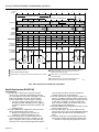
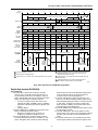
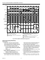
R4140G
Flame Safeguard Programming Controls
PRODUCT DATA
APPLICATION
The R4140G Flame Safeguard Programmers provide
flameout protection plus automatic sequencing of the burner
motor (blower), firing rate motor, ignition, pilot valve, and main
fuel valve(s) for commercial and industrial burners using gas,
oil, coal, or a combination of fuels.
FEATURES
• Approvals: Underwriters Laboratories Inc. listed or
component recognized, Canadian Standards
Association certified, and Factory Mutual approved for
automatic fired burners.
• The R4140 directly replaces the R4150 for most
applications and mounts on the same Q520A Wiring
Subbase.
• Low-high-low purge programmers.
• Field selectable main burner flame-establishing
period.
• Early spark termination (five-second ignition and fivesecond pilot only) available on some models.
• Plug-in, solid state, flame signal amplifiers are colorcoded and interchangeable to allow the use of any
type of flame detector-flame rod, photocell, infrared
detector, or ultraviolet detector.
• Amplifier capability includes three standard models,
three Dynamic Self-Check models, and one Dynamic
Ampli-Check® model.
Copyright © 1996 Honeywell Inc. • All Rights Reserved
• R7247C or R7476A Dynamic Self-Check Amplifier,
when used with an ultraviolet flame detector with a
self-checking shutter (R7247C with a C7012E or F;
R7476A with a C7076), tests all electronic components
in the flame detection system (amplifier and detector)
60 to 240 times a minute during burner operation and
shuts down the burner if the detection system fails.
• R7247B Dynamic Self-Check Amplifier, when used with
a rectifying flame rod (which is considered fail-safe),
or R7248B Dynamic Ampli-Check Amplifier, when used
with a C7015A Infrared (lead sulfide) Flame Detector,
tests the flame signal amplifier at least 150 times a
minute during burner operation and shuts down the
burner if the amplifier fails.
• All models feature capability of proving low fire position
of the firing rate motor before starting ignition trials.
• Provisions for connecting preignition or start
interlocks (depending on model) to prove the proper
conditions for startup, and for a combustion airflow
switch to prove airflow throughout the operating cycle.
• All models have 4-wire firing rate switching circuitry—
firing rate can be modulated while the burner is firing,
and the firing rate motor can be driven to both low and
high fire positions during prepurge.
• Safe start check at startup and during prepurge. If
flame relay 2K is holding in at startup, the programmer
cannot be started. If a flame (or a condition simulating
a flame) is detected during prepurge, ignition trials
cannot be started and the programmer recycles.
• Safety shutdown occurs on failure to ignite the pilot or
main burner, on loss of flame during the Run period,
or if the flame detection system fails (if a self-checking
system is used).
• All relays are visible, labeled, and easily accessible.
• Alarm terminal is available to operate an external, line
voltage alarm on safety shutdown.
Contents
Application ..........................................................................
Features ..............................................................................
Specifications ......................................................................
Ordering Information ...........................................................
Operation ............................................................................
Wiring ..................................................................................
X-XX UL
1
1
2
2
6
23
60-2337-3
R4140G FLAME SAFEGUARD PROGRAMMING CONTROLS
Interlock Circuits:
Start Interlocks (R4140G1049, G1056, G1064, G1114,
G1122, G1148 and G1171)—System controls must be
in proper positions or programmer will not start.
Preignition Interlocks (R4140G1007, G1015, and
G1106)—Must be closed to start programmer. Prevent
ignition trials if interlocks open during prepurge; timer
recycles the programmer and system restarts if
condition is self-correcting.
Running Interlocks (all models)—Must be closed (airflow
must be proven, fuel pressure must not be too low or
too high) within 9.5 seconds after startup or ignition
trials cannot be started. Running interlocks must remain
closed through the Run period or the automatic fuel
valves de-energize, the burner flame(s) goes out, and
the timer recycles the programmer.
Low Fire Interlock (all models)—Timer stops at 52 seconds
until low fire proving switch closes, indicating damper is
closed prior to ignition.
SPECIFICATIONS
IMPORTANT
The specifications given in this publication do not
include normal manufacturing tolerances. Therefore,
this unit may not match the listed specifications
exactly. Also, this product is tested and calibrated
under closely controlled conditions, and some minor
differences in performance can be expected if those
conditions are changed.
MODELS:
R4140G Flame Safeguard Programming Controls—Flame
Safeguard protection and sequencing controls for use on gas,
oil, coal, or combination burners. See Table 1 for models
available.
Table 1. Models Available.
a
b
c
Flame-Establishing
Period (sec)
Model
With
Cover a
Timer
Cycle
(sec)
Prepurge
(sec)
Early Spark
Terminationb
Pilotc
R4140G1007
Yes
120
60
No
10
R4140G1015
No
R4140G1106
No
Main Burner
Postpurge
(Field Selectable)c
(sec)
10 or 30
16
Interlock
Circuits
Firing Rate
Switching
Circuit
Preignition,
Running
120
60
No
10
10 or 15
16
(including
Airflow
Switch) and
Low Fire
4-wire
common,
Start,
high fire,
R4140G1049
No
120
60
Yes
10
10 or 30
16
R4140G1056
Yes
120
60
Yes
10
10 or intermittent
16
Running
low-fire,
R4140G1064
No
120
60
Yes
10
10 or intermittent
16
(including
modulate)
R4140G1114
No
180
70
Yes
10
10, 30, or 60
25
Airflow
R4140G1122
No
180
70
Yes
10
10, 30 or 60
25
Switch) and
R4140G1148
No
120
60
Yes
10
10 or 15
16
Low Fire
R4140G1171
No
180
70
Yes
10
10 or 15
25
202050C Cover with reset button; heavy duty, metal cover for outside panel mounting.
Early spark termination available on terminal 18 (5 second ignition and 5 second pilot only).
If used for direct spark ignition (oil or gas), the flame-establishing period is 10 seconds.
ORDERING INFORMATION
When purchasing replacement and modernization products from your TRADELINE® wholesaler or distributor, refer to the
TRADELINE® Catalog or price sheets for complete ordering number or specify order number. Order separately:
1. Flame detection system (amplifier and matching flame detector). See Table 4.
2. Q520A1089 or Q520A1121 Wiring Subbase.
3. Accessories, if desired.
If you have additional questions, need further information, or would like to comment on our products or services, please write or
phone:
1. Your local Home and Building Control Sales Office (check white pages of your phone directory).
2. Home and Building Control Customer Logistics
Honeywell Inc., 1885 Douglas Drive North
Minneapolis, Minnesota 55422-4386
In Canada—Honeywell Limited/Honeywell Limitée, 35 Dynamic Drive, Scarborough, Ontario M1V 4Z9.
International Sales and Service Offices in all principal cities of the world. Manufacturing in Australia, Canada, Finland, France,
Germany, Japan, Mexico, Netherlands, Spain, Taiwan, United Kingdom, U.S.A.
60-2337—3
2
R4140G FLAME SAFEGUARD PROGRAMMING CONTROLS
Safety Features:
Safe Start Check—For the presence of a flame (or a
condition simulating a flame) provided at startup and
during prepurge. If the flame relay 2K is pulled in at
startup, 2K2 is open and the programmer cannot be
started. If the flame relay 2K pulls in during prepurge
(before 57.5 seconds), 2K2 opens, relay 1K drops out,
and ignition trials cannot be started. Instead, the timer
completes its revolution and stops at the standby position
(zero seconds). If the flame relay 2K drops out by the end
of the cycle, the programmer restarts the system.
Safety Shutdown—Ignition transformer and all automatic
fuel valves de-energize. The lockout switch trips and
locks out the programmer. If used, the external alarm is
energized. The timer completes its revolution and locks
up at the stand-by position (zero seconds). The lockout
switch must be manually reset to restart the system.
Safety Shutdown occurs on:
• Failure to ignite the pilot (or first stage burner if using
direct spark ignition).
• Failure to light the main burner (unless monitoring
an intermittent pilot).
• Loss of flame during the Run period.
• Failure in the flame detection system (if a selfchecking system is used, see Table 4).
Flame Failure Response Time—2 to 4 seconds.
Lockout Switch Timing—30 seconds (nominal).
NOTE: Allowable inrush can be up to ten times the pilot duty
rating.
EXAMPLE: Pilot duty rating = 50 VA.
At 120V, running current is:
50
120 = 0.42A.
Maximum allowable inrush is ten times
0.42A = 4.2A.
Interlock Ratings:
See Table 3.
Table 3. Interlock Ratings.
Interlocks
Requirements must be abIe to
carry and break current to:
Limits, Burner Controller, Ignition transformer, pilot valve,
and Running Interlocks and main fuel valve(s).
(including airflow switch)
Start or Preignition
Interlocks
Electrical Ratings:
Voltage and Frequency: 120 Vac (102V minimum to 132V
maximum), 50/60 Hz.
R4140G1114: 240 Vac, 60 Hz.
R4140G1122: 208 Vac, 60 Hz.
Programmer relay 1K (5W max).
Ambient Operating Temperature Ratings:
Minimum: Minus 40°F (minus 40°C).
Maximum:
Programmer Mounting Position
NOTE: Use of a 50 Hz power supply lengthens the
sequence timings by a factor of 1.2.
Power Consumption (With No Loads Connected to Output
Terminals): 13W maximum.
Maximum Total Connected Load: 2000 VA.
Standard Vertical (With Handle Up)
Any Other
+150°F (+66°C)
+135°F (+57°C)
Storage Temperature Ratings:
Minus 60°F to plus 150°F (minus 51°C to plus 66°C).
Mounting:
3-sided Q520A1089 Wiring Subbase, or 4-sided Q520A1121
Wiring Subbase; both have 20 knife-blade contacts (subbase
ordered separately).
Terminal Ratings:
See Table 2.
Table 2. Terminal Ratings.
Dimensions:
See Fig. 1 and 2.
Maximum Rating at
120 Vac, 60 Hz
Terminal
Typical Load
5 or 6
Ignition
Transformer/Pilot
Valve/First Stage
Fuel Valve
4.5A ignition and 50 VA pilot duty or
2.5A ignition and 75 VA pilot duty
Weight (Without Plug-in Flame Signal Amplifier and
202050C Cover):
4 lb, 12 oz (2.15 kg).
7
Main Fuel Valve(s)
(solenoid/motorized
/diaphragm) and
Vent Valve if
required
250 VA pilot duty or 65 VA pilot duty
in parallel with motorized valve(s)
using a total of 1150 VA locked
rotor (inrush),460 VA to open, and
250 VA to hold or motorized
valve(s) using a total of 1500 VA
locked rotor (inrush), 600 VA to
open, and 250 VA to hold
Flame Detection System (Ordered Separately):
Plug-in Flame Signal Amplifier and matching Flame Detector;
see Table 4.
8
Burner Motor
(blower)
9.8A full load, 58.8A locked rotor
(inrush)
9
120V Alarm
75 VA pilot duty
10, 11, 12,
and 14
Firing Rate
(damper) Motor
Contacts
50 VA pilot duty
18
(if available)
Ignition
Transformer
Approvals:
Underwriters Laboratories Inc. Listed Section of Primary
Safety Control (120V Models With Covers): File No.
MP268; Guide No. MCCZ.
Underwriters Laboratories Inc. Component Recognized
(120V Models Without Covers): File No. MP268; Guide
No. MCCZ2.
Canadian Standards Association Certified: File No.
LR1620.
Factory Mutual Approved: Report No. 24180.
4.5A ignition
3
60-2337—3
R4140G FLAME SAFEGUARD PROGRAMMING CONTROLS
LOCKOUT SWITCH
RESET BUTTON
2-11/32 (60)
2-3/8 (60)
47/64
(19)
35/64
(14)
202050C COVER
1-51/64
(46)
7/8 (22) DIAMETER KNOCKOUT (2)
2-5/64
(53)
3/8 (10) (4)
13/64 (5) DIAMETER (4)
(FOR MOUNTING ON
4 X 4 [102 X 102] JUNCTION BOX)
5/8 (16) (4)
6-1/2
(165)
3
3-3/8
(86)
6-5/32
(156)
5
4
L1
18
6
9
L2
17
7
10
12
16
8
11
13
15
G
F
14
7-3/16 (183)
202050C COVER
1-3/4
(45)
15/16
(24) (2)
6
(152)
7/8 (22) DIAMETER
KNOCKOUT (2)
31/32
(25) (2)
1-27/32
(47)
1
5-7/8
(149)
3-3/8 (86)
7 -1/16 (179)
5-5/8
(143)
7-3/16 (183)
31/32
(25)
1-13/32 (36)
2-11/32 (60)
1-13/32 (36)
1-3/4
(45)
(ON Q520A1089 3-SIDED WIRING SUBBASE)
3/4
(19)
Fig. 2. Mounting dimensions of the R4140 Programmer
on the Q520A wiring subbase in in. (mm).
7/8 (22) DIAMETER KNOCKOUT (4)
1
OPEN ON 3-SIDED Q520A1089.
M6776
Fig. 1. Mounting dimensions of the Q520A
wiring subbase in in. (mm).
60-2337—3
M6777
4
R4140G FLAME SAFEGUARD PROGRAMMING CONTROLS
R1298020 Cable; for flame detector (F lead-wire)
installations in a high temperature environment; rated
up to 400°F (204°C) for continuous duty; tested for
operation up to 600V and breakdown up to 7500V.
R1239001 High Tension Ignition Cable; for ignition
installations in a contaminating environment; very
resistant to severe conditions of oil, heat, and corona,
and tested to withstand high voltages up to
25,000V rms in a salt bath for one minute without
breakdown; rated at 200°F (93°C) for continuous duty,
and up to 350°F (197°C) for intermittent use.
Q624A Solid State Spark Generator; prevents detection of
ignition spark when properly applied with flame
detection systems using C7027, C7035, or C7044
Minipeeper Ultraviolet Flame Detectors. For use only
with gas pilots.
FSP5004 Tester; provides a quick operational check of
most R4140 Flame Safeguard Programming Controls.
Q520E1002 Service Tool; allows any of the programmer
terminals to be monitored while the programmer is
operating.
Accessories:
W136A Test Meter (includes 117053 Meter Connector
Plug); has SPL position with damping for testing selfchecking flame detection systems.
117053 Meter Connector Plug (for older W136A models).
123514A Flame Simulator (for use with R7247A
Rectification Amplifiers).
123514B Flame Simulator (for use with R7249A Ultraviolet
Amplifiers).
139695C (Series 1 and 2) Cover with reset button; heavy
duty, metal cover for outside panel mounting.
202050C (Series 3) Cover with reset button; heavy duty,
metal cover for outside panel mounting.
118760B (Series 1 and 2) Remote Reset Cover; heavy
duty, metal cover with remote reset assembly; 120V,
60 Hz solenoid.
202051B (Series 3) Remote Reset Cover; heavy duty,
metal cover with remote reset assembly; 120V, 60 Hz
solenoid.
R1061012 Ignition Cable; for ignition installations in a high
temperature environment; rated at 350°F (177°C) for
continuous duty, and up to 500°F (260°C) for
intermittent use; tested to 25,000V.
Table 4. Flame Detection Systems
NOTE: Neither the R414G1114 or the R4140G1122 can be used with the C7012E or F Purple Peeper Ultraviolet Flame
Detector and with the R7247C Dynamic Self-Check Amplifier.
Plug-In Flame Signal Amplifiers
Type
Rectification
Color
Green
SelfChecking
No
Ultraviolet
Fuel
Type
Models
R7247A
2 to 4 sec
Gas
Rectifying
Flame Rods
Holdersa:
R7247A,
R7247B b
2 to 4 sec
Oil
Rectifying
Photocells c
C7003, C7010, C7013, C7014.
Gas,
Oil,
Coal
Ultraviolet
(Purple
Peeper)
C7004, C7007, C7011.
Complete assemblies: C7005,
C7008, C7009, Q179.
C7012A or C.
R7147B b
2 to 4 sec
Gas
Rectifying
Flame Rods
R7247Cd
2 to 4 sec
Gas,
Oil,
Coal
Ultraviolet
(Purple
Peeper)
No
R7248A
2 to 4 sec
Gas,
Oil,
Coal
Infrared
(Lead
Sulfide)
C7015.
Dynamic
AmpliCheck®
R7248B b
2 to 4 sec
Gas,
Oil,
Coal
Infrared
(Lead
Sulfide)
C7015.
Purple
No
R7249A
2 to 4 sec
Gas,
Oil
Ultraviolet
C7027, C7035, C7044.
(Minipeeper)
Blue
Dynamic
SelfCheck
R7476A d
2 to 4 sec
Gas,
Oil,
Coal
Ultraviolet
(Adjustable
Sensitivity)
Dynamic
SelfCheck
Infrared
Model
Applicable Flame Detectors
Flame Failure
Response Time
Red
Holdersa: C7004, C7007, C7011.
Complete Assemblies: C7005,
C7008, C7009, Q179.
C7012E or F
C7076.
a
b
Order flame rod separately; see Instructions for the holder.
Circuitry tests the flame signal amplifier at least 150 times a minute during burner operation and shuts down the burner if the
amplifier fails.
c Use only Honeywell part no. 38316 Photocell.
d Circuitry tests all electronic components in the flame detection system (amplifier and detector) 60 to 240 times a minute during
burner operation and shuts down the burner if the detection system fails.
5
60-2337—3
R4140G FLAME SAFEGUARD PROGRAMMING CONTROLS
OPERATION
Models with Preignition Interlocks
to each timer contact. Refer to Fig. 4 and the Step-by-Step
Operation section.
Fig. 3 shows all contacts in the standby position (zero
seconds). The opening and closing times are shown adjacent
R4140G1007/G1015 SCHEMATIC
(WITH/WITHOUT HEAVY DUTY COVER)
INTERNAL
120V, 60 HZ
POWER SUPPLY
L2
L1
(HOT)
1
EXTERNAL
UNDERLINED O OR C DENOTES SNAP ACTION OF CONTACT.
A TIMER CONTACTS SNAP CLOSED.
B CONTACTS SNAP OPEN.
O—OPENING TIME
C—CLOSING TIME
LS DENOTES LOCKOUT SWITCH; HTR DENOTES HEATER
MASTER
SWITCH
L1
1
L2
2
3
3
4
G
9
13
5
8
12
NUMBERS BELOW
DESIGNATE LINE
LOCATIONS OF
RELAY CONTACTS.
(UNDERLINE
INDICATES A
NORMALLY CLOSED
CONTACT.)
10
FLAME SIGNAL
METER JACK
F
PLUG-IN AMPLIFIER
5
FLAME
DETECTOR
6
7
17
7
17
TIP JACK
8
M11B
C-15 O-70
11
TO
TERMINAL
8
2K
2
2K3
9
10
M7A
C-57.5 O-111
BURNER
CONTROLLER
LIMITS
11
1K3
12
16
13
1K1
14
15
M1B
8
C-4
O-120
16
17
M3A
O-52 C-66
13
LOW FIRE
SWITCH
NORM
M2B
O-70
C-113.5
2K2
TEST
LS HTR
5
RUNNING
INTERLOCKS
(INCLUDING
AIRFLOW SWITCH)
1K2
2K - 13, 9, 8
1K - 14, 14, 11
LS2
3
PREIGNITION
INTERLOCKS
1K
LS - 19, 9
M7B
O-9.5 C-116
4
M9A
C-57.5 O-109.5
16
2K1
M4A
C-60
O-85
M6B
C-50 O-80
6
M2A
C-70
O-109.5
M5B
O-104
C-108
4
30 SECOND
INTERRUPTED
PILOT/IGNITION
5
MAIN FUEL
VALVES (S)
7
TIMER SWITCH
10 SECOND 3
INTERRUPTED
PILOT/IGNITION
TIMER MOTOR
BURNER MOTOR
(BLOWER)
18
LS1
19
9
120 V ALARM
10
B
B
11
R
R
12
W
W
14
FIRING
RATE
MOTOR
20
HIGH FIRE
21
M10A C-4 O-41
22
COMMON
M10B O-4 C-45
23
MODULATE
M8A C-100 O-112
24
1
2
M8B O-100 C-116
PROVIDE DISCONNECT MEANS AND OVERLOAD PROTECTION
AS REQUIRED.
TERMINAL 17 IS USED ONLY TO DRIVE THE SHUTTER ON A C7012E OR F
OR A C7076A ULTRAVIOLET FLAME DETECTOR WITH SELF-CHECKING
FEATURE. POWER TO DRIVE THE SHUTTER IS APPLIED TO TERMINAL 17
FROM TERMINAL 8 THROUGH A SOLID STATE SWITCH IN THE R7247C
OR R7476A DYNAMIC SELF-CHECK AMPLIFIER. REFER TO SAMPLE BLOCK
DIAGRAM OF FIELD WIRING.
LOW FIRE
SERIES 90
CONTROLLER
6
3
10 SECOND MAIN BURNER FLAME-ESTABLISHING PERIOD.
4
30 SECOND MAIN BURNER FLAME-ESTABLISHING PERIOD.
5
FOR DIRECT SPARK IGNITION (GAS OR OIL,) A JUMPER IS INSTALLED
BETWEEN TERMINALS 6 AND 7. REFER TO SAMPLE BLOCK DIAGRAM
OF FIELD WIRING FOR HOOKUP.
6
USE A SERIES 90 MODULATING MOTOR IF MODULATION IS REQUIRED.
M10149
Fig. 3. Simplified schematic diagram of R4140G1015 Programmer.
60-2337—3
6
R4140G FLAME SAFEGUARD PROGRAMMING CONTROLS
TIMER 0
SECONDS
10
20
30
40
50
60
70
80
90
100
110
6
PREIGNITION INTERLOCKS
RUN 5
PERIOD
RUNNING INTERLOCKS (PROVEN AIRFLOW)
BURNER
MOTOR
(BLOWER)
INTERRUPTED
PILOT/IGNITION
MAIN FUEL
VALVE(S)
(GAS OR OIL)
8
PURGE
5
1
5
10 SECONDS
6
30 SECONDS
7
HIGH FIRE POSITION
FIRING RATE
MOTOR
SWITCHING
STOP
STOP
STOP
3
START
START
TIMER
MOTOR
MAIN
IGN
PILOT
PREPURGE
START
TIMER DIAL
120
10 TO 11
MODULATE
LOW FIRE POSITION
1
LOW
12 TO 11
LOW
14 TO 11
2
2
2
2
ACTUAL
DAMPER
OPERATION
4
MOTOR
DRIVES
DAMPER
CLOSED
MOTOR
DRIVES
DAMPER
OPEN
3
1
TERMINAL NUMBERS (CIRCLED).
2
SLOPE DEPENDS ON MOTOR TIMING.
3
TIMER STOPS AT 52 SECONDS UNTIL LOW FIRE PROVING SWITCH CLOSES.
MOTOR DRIVES
DAMPER CLOSED
4
FIRING RATE MOTOR MODULATES UNDER CONTROL OF SERIES 90
CONTROLLER FROM 100 TO 112 SECONDS (INCLUDING RUN
PERIOD WHILE BURNER IS FIRING).
5
TIMER STOPS AT 104 SECONDS FOR THE RUN PERIOD WITH THE
BURNER FIRING.
6
RUNNING INTERLOCKS (INCLUDING THE AIRFLOW SWITCH)
MUST REMAIN CLOSED THROUGH THE RUN PERIOD.
M10054
Fig. 4. Timer sequence for R4140G1015 Programmer.
Step-By-Step Operation (R4140G1015)
and ignition trials cannot be started. Running interlocks
must remain closed through the Run period or the
system shuts down; the timer completes its revolution
and recycles the programmer.
15 seconds—M11B closes; flame relay 2K can pull in if a
flame (or a condition simulating a flame) is detected. If
detected during prepurge (until 57.5 seconds), 2K pulls
in, 2K2 opens, 1K drops out, and the system shuts
down; the timer completes its revolution and recycles
the programmer (if 2K dropped out).
45 seconds—M10B closes; firing rate motor drives toward
low fire position (closed).
52 seconds—M3A opens; timer stops until the low fire
proving switch closes; timer can be stopped by opening
the timer switch (until 66 seconds when M3A closes
again).
57.5 seconds—M9A closes; the LS HTR (lockout switch
heater) begins heating in preparation for ignition trials.
— M7A closes, bypassing the preignition interlocks.
Start And Prepurge
0 seconds—On a call for heat, the burner controller
contacts close. If the limits and preignition interlocks
are closed and flame relay 2K is not holding in, relay 1K
pulls in through M7B, LS2, 2K2, and the LS HTR
(lockout switch heater—thus proving its continuity).
— 1K1 closes and 1K2 opens, timer motor starts
(through 1K1, M3A, and M5B), power is applied to
terminal 8, starting the burner motor (blower); 1K3
closes.
— Prepurge begins.
4 seconds—M10A closes, M10B opens; firing rate motor
drives toward high fire position (open).
—M1B closes, bypassing 1K1; the timer can complete
its revolution if shutdown occurs.
9.5 seconds—M7B opens; running interlocks must close
(airflow must be proven) or 1K drops out, 1K3 opens,
7
60-2337—3
R4140G FLAME SAFEGUARD PROGRAMMING CONTROLS
Ignition Trials
60 seconds—M4A closes; power is applied to terminals 5
and 6, energizing the ignition transformer and pilot
valve (or main fuel valve(s) on terminal 7 if using direct
spark ignition).
— When a flame is detected, relay 2K pulls in, 2K2
opens, and the LS HTR stops heating; 2K1 and
2K3 close.
66 seconds—M3A closes, bypassing the low fire switch
and the timer switch.
70 seconds—M2B opens; pilot or ignition trial ends; a
flame must be detected by this time (2K pulled in and
2K1 closed) or safety shutdown occurs and the lockout
switch trips.
— M2A closes; power is applied to terminal 7,
energizing the main fuel valve(s).
— M11B opens; prevents 2K from pulling in after this
time.
80 seconds—M6B opens; 10 second interrupted pilot/
ignition (terminal 5) is de-energized.
100 seconds—M4A opens; 30 second interrupted pilot/
ignition (terminal 6) is de-energized.
— M8A closes, M8B opens; firing rate motor is
released to modulate under control of the Series 90
Controller.
104 seconds—M5B opens; timer stops with the system in
the Run condition.
60-2337—3
Run Period (Burner is Firing)
Postpurge And Stop
104 seconds—When the operating setpoint is reached, the
burner controller contacts open; relay 1K and the main
fuel valve(s) (terminal 7) de-energize.
— 1K2 closes; timer motor starts; postpurge begins.
— When the flame goes out, relay 2K drops out.
112 seconds—M8A opens; firing rate motor stops
modulating under control of the Series 90 Controller.
116 seconds—M8B closes; firing rate motor drives toward
low fire position (closed).
120 seconds—M1B opens; timer and burner motor stop;
cycle ends.
Fig. 5 shows all contacts in the standby position (zero
seconds). The opening and closing times are shown adjacent
to each timer contact. Refer to Fig. 6 and the Step-by-Step
Operation section.
8
R4140G FLAME SAFEGUARD PROGRAMMING CONTROLS
120V, 60 HZ
POWER SUPPLY
L2
L1
(HOT)
1
R4140G1106 SCHEMATIC
INTERNAL
EXTERNAL
UNDERLINED O OR C DENOTES SNAP ACTION OF CONTACT.
A TIMER CONTACTS SNAP CLOSED.
B CONTACTS SNAP OPEN.
O—OPENING TIME
C—CLOSING TIME
LS DENOTES LOCKOUT SWITCH; HTR DENOTES HEATER
1
MASTER
SWITCH
L2
L1
2
3
3
4
G
9
13
5
8
12
NUMBERS BELOW
DESIGNATE LINE
LOCATIONS
RELAY CONTACTS.
(UNDERLINE
INDICATES A
NORMALLY CLOSED
CONTACT.)
10
FLAME SIGNAL
METER JACK
F
PLUG-IN AMPLIFIER
5
FLAME
DETECTOR
6
7
17
7
17
8
11
10
M7A
C-57.5 O-111
BURNER
CONTROLLER
LIMITS
11
12
1K1
14
M1B
B
C-4
O-120
16
17
M3A
O-52 C-66
13
LOW FIRE
SWITCH
NORM
TEST
TIMER SWITCH
LS HTR
5
RUNNING
INTERLOCKS
(INCLUDING
AIRFLOW SWITCH)
1K2
15
2K2
3
PREIGNITION
INTERLOCKS
13
LS - 22, 8
M2B
O-70
C-113.5
1K3
16
2K - 16, 10, 8
1K - 17, 17, 12
LS2
M7B
O-9.5 C-116
4
1K
8
2K3
9
M9A
C-57.5 O-109.5
16
TO
2K
2
TIP JACK
M11B
C-15 O-70
2K1
M4A
C-60
O-85
M6B
C-50 O-80
3
9
15 SECOND
INTERRUPTED
PILOT/IGNITION
6
M2A
C-70
O-109.5
M5B
O-104
C-108
7
7
5
TIMER MOTOR
8
10 SECOND
INTERRUPTED
PILOT/IGNITION
MAIN FUEL
VALVES (S) 4
BURNER
MOTOR
18
LS1
19
9
ALARM
10
B
20
HIGH FIRE
21
M10A C-4 O-41
22
COMMON
M10B O-4 C-45
23
MODULATE
M8A C-100 O-112
24
M8B O-100 C-116
1
PROVIDE DISCONNECT MEANS AND OVERLOAD PROTECTION
AS REQUIRED
2
TERMINAL 17 IS USED ONLY TO DRIVE THE SHUTTER ON A C7012E OR F
PURPLE PEPPER ULTRAVIOLET FLAME DETECTOR WITH SELF-CHECKING
FEATURE. POWER TO DRIVE THE SHUTTER IS APPLIED TO TERMINAL 17
FROM TERMINAL 8 THROUGH A SOLID STATE SWITCH IN THE R7247C
DYNAMIC SELF-CHECK AMPLIFIER. REFER TO SAMPLE BLOCK DIAGRAM
OF FIELD WIRING.
3
FOR DIRECT SPARK IGNITION OR OIL, REFER TO SAMPLE BLOCK DIAGRAM
OF FIELD WIRING FOR HOOKUP OF IGNITION AND MAIN OIL VALVE SOLENOID.
4
SOME AUTHORITIES HAVING JURISDICTION PROHIBIT THE WIRING OF ANY LIMIT
OR OPERATING CONTACTS IN SERIES WITH THE MAIN FUEL VALVE(S).
LOW FIRE
B
11
R
R
12
W
W
14
FIRING
RATE
MOTOR
SERIES 90
CONTROLLER
6
5
TIMER SWITCH IS SHOWN IN "NORM" POSITION; IT IS OPEN IN "TEST"
POSITION.
6
USE A SERIES 90 MODULATING MOTOR IF MODULATION IS REQUIRED.
7
FOR DIRECT SPARK IGNITION (OIL OR GAS), A JUMPER IS INSTALLED
BETWEEN TERMINALS 6 AND 7. REFER TO SAMPLE BLOCK
DIAGRAM OF FIELD WIRING FOR HOOKUP.
8
10 SECOND MAIN BURNER FLAME-ESTABLISHING PERIOD.
9
15 SECOND MAIN BURNER FLAME-ESTABLISHING PERIOD.
M10044
Fig. 5. Simplified schematic diagram of R4140G1106 Programmer.
9
60-2337—3
R4140G FLAME SAFEGUARD PROGRAMMING CONTROLS
TIMER 0
SECONDS
10
20
30
40
50
60
70
80
90
100
110
6
PREIGNITION INTERLOCKS
RUN
PERIOD
RUNNING INTERLOCKS (PROVEN AIRFLOW)
BURNER
MOTOR
(BLOWER)
INTERRUPTED
PILOT/IGNITION
MAIN FUEL
VALVE(S)
(GAS OR OIL)
8
PURGE
5
1
5
10 SECONDS
6
15 SECONDS
7
HIGH FIRE POSITION
FIRING RATE
MOTOR
SWITCHING
STOP
STOP
STOP
3
START
START
TIMER
MOTOR
MAIN
IGN
PILOT
PREPURGE
START
TIMER DIAL
120
10 TO 11
MODULATE
LOW FIRE POSITION
1
LOW
12 TO 11
LOW
14 TO 11
2
2
2
2
ACTUAL
DAMPER
OPERATION
4
MOTOR
DRIVES
DAMPER
CLOSED
MOTOR
DRIVES
DAMPER
OPEN
3
1
TERMINAL NUMBERS (CIRCLED).
2
SLOPE DEPENDS ON MOTOR TIMING.
3
TIMER STOPS AT 52 SECONDS UNTIL LOW FIRE PROVING SWITCH CLOSES.
MOTOR DRIVES
DAMPER CLOSED
4
FIRING RATE MOTOR MODULATES UNDER CONTROL OF SERIES 90
CONTROLLER FROM 100 TO 112 SECONDS (INCLUDING RUN
PERIOD WHILE BURNER IS FIRING).
5
TIMER STOPS AT 164 SECONDS FOR THE RUN PERIOD WITH
THE BURNER FIRING.
6
RUNNING INTERLOCKS (INCLUDING THE AIRFLOW SWITCH)
MUST REMAIN CLOSED THROUGH THE RUN PERIOD.
M10052
Fig. 6. Timer sequence for R4140G1106 Programmer.
Step-By-Step Operation (R4140G1106)
Start and Prepurge
0 seconds—On a call for heat, the burner controller
contacts close. If the limits and preignition interlocks
are closed and flame relay 2K is not holding in, relay 1K
pulls in through M7B, LS2, 2K2, and the LS HTR
(lockout switch heater—thus proving its continuity).
— 1K1 closes and 1K2 opens; timer motor starts
(through 1K1, M3A, and M5B); power is applied to
terminal 8, starting the burner motor (blower); 1K3
closes.
— Prepurge begins.
4 seconds—M10A closes, M10B opens; firing rate motor
drives toward high fire position (open).
— M1B closes, bypassing 1K1; the timer can
complete its revolution if shutdown occurs.
9.5 seconds—M7B opens; running interlocks must be
closed (airflow must be proven) or 1K drops out, 1K3
opens, and ignition trials cannot be started. Running
interlocks must remain closed through the Run period
60-2337—3
or the system shuts down; the timer completes its
revolution and recycles the programmer.
15 seconds—M11B closes; flame relay 2K can pull in if a
flame (or a condition simulating a flame) is detected. If
detected during prepurge (until 57.5 seconds), 2K pulls
in, 2K2 opens, 1K drops out, and the system shuts
down; the timer completes its revolution and recycles
the programmer (if 2K dropped out).
45 seconds—M10B closes; firing rate motor drives toward
low fire position (closed).
52 seconds—M3A opens; timer stops until the low fire
proving switch closes; timer can be stopped by opening
the timer switch (until 66 seconds when M3A closes
again).
57.5 seconds—M9A closes; the LS HTR (lockout switch
heater) begins heating in preparation for ignition trials.
— M7A closes, bypassing the preignition interlocks.
10
R4140G FLAME SAFEGUARD PROGRAMMING CONTROLS
Ignition Trials
60 seconds—M4A closes; power is applied to terminals 5
and 6, energizing the ignition transformer and pilot
valve (or main fuel valve(s) on terminal 7 If using direct
spark ignition).
— When a flame is detected, relay 2K pulls in, 2K2
opens, and the LS HTR stops heating; 2K1 and
2K3 close.
66 seconds—M3A closes, bypassing the low fire switch
and the timer switch.
70 seconds—M2B opens; pilot or ignition trial ends; a
flame must be detected by this time (2K pulled in and
2K1 closed) or safety shutdown occurs and the lockout
switch trips.
— M2A closes; power is applied to terminal 7,
energizing the main fuel valves(s).
— M11B opens; prevents 2K from pulling in after this
time.
80 seconds—M6B opens; 10 second interrupted pilot/
ignition (terminal 5) de-energizes.
85 seconds—M4A opens; 15 second interrupted pilot/
ignition (terminal 6) de-energizes.
100 seconds—M8A closes, M8B opens; firing rate motor is
released to modulate under control of the Series 90
Controller.
104 seconds—M5B opens; timer stops with the system in
the run condition.
Run Period (Burner is Firing)
Postpurge and Stop
104 seconds—When the operating setpoint is reached, the
burner controller contacts open; relay 1K and the main
fuel valve(s) (terminal 7) are de-energized.
— 1K2 closes; timer motor starts; postpurge begins.
— When the flame goes out, relay 2K drops out.
112 seconds—M8A opens; firing rate motor stops
modulating under control of the Series 90 Controller.
116 seconds—M8B closes; firing rate motor drives toward
low fire position (closed).
120 seconds—M1B opens; timer and burner motor stop;
cycle ends.
Models with Start Interlocks
Fig. 7 shows all contacts in the standby position (zero
seconds). The opening and closing times are shown adjacent
to each timer contact. Refer to Fig. 8 and the Step-by-Step
Operation section.
11
60-2337—3
R4140G FLAME SAFEGUARD PROGRAMMING CONTROLS
120V, 60 HZ
POWER SUPPLY
L2
L1
(HOT)
1
R4140G1049 SCHEMATIC
(WITH/WITHOUT HEAVY DUTY COVER)
INTERNAL
EXTERNAL
UNDERLINED O OR C DENOTES SNAP ACTION OF CONTACT.
A TIMER CONTACTS SNAP CLOSED.
B CONTACTS SNAP OPEN.
O—OPENING TIME
C—CLOSING TIME
LS DENOTES LOCKOUT SWITCH; HTR DENOTES HEATER
MASTER
SWITCH
L1
1
L2
2
3
3
4
G
9
13
5
8
12
NUMBERS BELOW
DESIGNATE LINE
LOCATIONS OF
RELAY CONTACTS.
(UNDERLINE
INDICATES A
NORMALLY CLOSED
CONTACT.)
10
FLAME SIGNAL
METER JACK
F
PLUG-IN AMPLIFIER
5
FLAME
DETECTOR
6
17
7
17
TIP JACK
8
9
LIMITS
BURNER
CONTROLLER 3
10
2
M11B
C-15 O-70
7
16
2K3
4
M9A
C-57.5 O-111
LS HTR
M2B
O-70
C-113.5
1K3
RUNNING INTERLOCKS
(INCLUDING AIRFLOW SWITCH)
15
2K1
1K1
1K2
17
18
M3A
O-52 C-66
M1B
8
C-4
LOW FIRE
O-120
SWITCH
19
20
13
NORM
TEST
M4A
C-60
O-85
M6B
C-50 O-80
M2A
C-70
O-109.5
M5B
O-104
C-108
TIMER SWITCH
18
5 SECOND
IGNITION
5
10 SECOND 5
INTERRUPTED
PILOT/IGNITION
M9B
C-30
O-65
14
16
2K - 16, 10, 8
1K - 17, 17, 12
2K2
3
13
1K
LS - 22, 8
M7B
O-9.5 C-116
11
12
16
TO
TERMINAL
8
2K
START
INTERLOCK(S) 4
11
6
6
30 SECOND
INTERRUPTED
PILOT/IGNITION
7
MAIN FUEL
VALVES (S)
7
TIMER MOTOR
BURNER MOTOR
(BLOWER)
21
LS1
22
9
120 V ALARM
10
B
B
11
R
R
12
W
W
14
FIRING
RATE
MOTOR
23
HIGH FIRE
24
M10A C-4 O-41
25
COMMON
M10B O-4 C-45
MODULATE
26
M8A C-100 O-112
27
M8B O-100 C-116
LOW FIRE
SERIES 90
CONTROLLER
8
1
PROVIDE DISCONNECT MEANS AND OVERLOAD PROTECTION
AS REQUIRED.
4
IF START INTERLOCK(S) IS NOT USED, A JUMPER IS INSTALLED
BETWEEN TERMINALS 16 AND 4 ON THE WIRING SUBBASE.
2
TERMINAL 17 IS USED ONLY TO DRIVE THE SHUTTER ON A C7012E OR F
OR A C7076A ULTRAVIOLET FLAME DETECTOR WITH SELF-CHECKING
FEATURE. POWER TO DRIVE THE SHUTTER IS APPLIED TO TERMINAL 17
FROM TERMINAL 8 THROUGH A SOLID STATE SWITCH IN THE R7247C
OR R7476A DYNAMIC SELF-CHECK AMPLIFIER. REFER TO SAMPLE BLOCK
DIAGRAM OF FIELD WIRING.
5
10 SECOND MAIN BURNER FLAME-ESTABLISHING PERIOD.
6
30 SECOND MAIN BURNER FLAME-ESTABLISHING PERIOD.
7
FOR DIRECT SPARK IGNITION (GAS OR OIL), A JUMPER IS INSTALLED
BETWEEN TERMINALS 6 AND 7. REFER TO SAMPLE BLOCK DIAGRAM
OF FIELD WIRING FOR HOOKUP.
8
USE A SERIES 90 MODULATING MOTOR IF MODULATION IS REQUIRED.
3
TERMINAL 16, ON THE WIRING SUBBASE ONLY, IS USED AS A TIE POINT.
M10155
Fig. 7. Simplified schematic diagram of R4140G1049 Programmer.
60-2337—3
12
R4140G FLAME SAFEGUARD PROGRAMMING CONTROLS
TIMER 0
SECONDS
10
20
30
40
50
60
70
80
90
100
110
6
RUN 5
PERIOD
RUNNING INTERLOCKS (PROVEN AIRFLOW)
IGN
BURNER
MOTOR
(BLOWER)
5 SECOND
IGNITION
INTERRUPTED
PILOT/IGNITION
MAIN FUEL
VALVE(S)
(GAS OR OIL)
PURGE
5
1
18
5
10 SECONDS
6
30 SECONDS
7
HIGH FIRE POSITION
FIRING RATE
MOTOR
SWITCHING
STOP
STOP
STOP
START
3
8
MAIN
PILOT
START
TIMER
MOTOR
PREPURGE
START
TIMER DIAL
120
10 TO 11
MODULATE
LOW FIRE POSITION
1
LOW
12 TO 11
LOW
14 TO 11
2
2
2
2
ACTUAL
DAMPER
OPERATION
4
MOTOR
DRIVES
DAMPER
CLOSED
MOTOR
DRIVES
DAMPER
OPEN
3
1
TERMINAL NUMBERS (CIRCLED).
2
SLOPE DEPENDS ON MOTOR TIMING.
3
TIMER STOPS AT 52 SECONDS UNTIL LOW FIRE PROVING SWITCH CLOSES.
MOTOR DRIVES
DAMPER CLOSED
4
FIRING RATE MOTOR MODULATES UNDER CONTROL OF SERIES 90
CONTROLLER FROM 100 TO 112 SECONDS (INCLUDING RUN
PERIOD WHILE BURNER IS FIRING).
5
TIMER STOPS AT 104 SECONDS FOR THE RUN PERIOD WITH THE
BURNER FIRING.
6
RUNNING INTERLOCKS (INCLUDING THE AIRFLOW SWITCH)
MUST REMAIN CLOSED THROUGH THE RUN PERIOD.
M10055
Fig. 8. Timer sequence for R4140G1049 Programmer.
Step-By-Step Operation (R4140G1049)
Start and Prepurge
0 seconds—On a call for heat, the burner controller
contacts close. If the limits and start interlock(s) are
closed and flame relay 2K is not holding in, relay 1K
pulls in through M7B, 2K2, the LS HTR (lockout switch
heater—thus proving its continuity), and LS2.
— 1K1 closes and 1K2 opens; timer motor starts
(through 1K1, M3A, and M5B); power is applied to
terminal 8, starting the burner motor (blower); 1K3
closes.
— Prepurge begins.
4 seconds—M10A closes, M10B opens; firing rate motor
drives toward high fire position (open).
— M1B closes, bypassing 1K1; the timer can
complete its revolution if shutdown occurs.
9.5 seconds—M7B opens; running interlocks must be
closed (airflow must be proven) or 1K drops out, 1K3
opens, and ignition trials cannot be started. Running
interlocks must remain closed through the Run period
or the system shuts down; the timer completes its
revolution and recycles the programmer.
15 seconds—M11B closes; flame relay 2K pulls in if a
flame (or a condition simulating a flame) is detected. If
detected during prepurge (until 57.5 seconds), 2K pulls
in, 2K2 opens, 1K drops out, and the system shuts
down; the timer completes its revolution and recycles
the programmer (if 2K dropped out).
45 seconds—M10B closes; firing rate motor drives toward
low fire position (closed).
52 seconds—M3A opens; timer stops until the low fire
proving switch closes; timer can be stopped by opening
the timer switch (until 66 seconds when M3A closes
again).
57.5 seconds—M7A closes; the LS HTR (lockout switch
heater) begins heating in preparation for ignition trials.
13
60-2337—3
R4140G FLAME SAFEGUARD PROGRAMMING CONTROLS
Ignition Trials
60 seconds—M4A closes; power is applied to terminals
18, 5, and 6, energizing the ignition transformer and
pilot valve (or main fuel valve(s) on terminal 7 if using
direct spark ignition).
— When a flame is detected, relay 2K pulls in, 2K2
opens, and the LS HTR stops heating; 2K1 and
2K3 close.
65 seconds—M9B opens; 5 second ignition (terminal 18)
is de-energizes (pilot only until 70 seconds).
66 seconds—M3A closes, bypassing the low fire switch
and the timer switch.
70 seconds—M2B opens; pilot or ignition trial ends; a
flame must be detected by this time (2K pulled in and
2K1 closed) or safety shutdown occurs and the lockout
switch trips.
— M2A closes; power is applied to terminal 7,
energizing the main fuel valve(s).
— M11B opens; prevents 2K from pulling in after this
time.
80 seconds—M6B opens; 10 second interrupted pilot/
ignition (terminal 5) de-energizes.
100 seconds—M4A opens; 30 second interrupted pilot/
ignition (terminal 6) de-energizes.
— M8A closes, M8B opens; firing rate motor is
released to modulate under control of the
Series 90 Controller.
104 seconds—M5B opens; timer stops with the system in
the run condition.
60-2337—3
Run Period (Burner is Firing)
Postpurge and Stop
104 seconds—When the operating setpoint is reached, the
burner controller contacts open; relay 1K and the main
fuel valve(s) (terminal 7) de-energize.
— 1K2 closes; timer motor starts; postpurge begins.
— When the flame goes out, relay 2K drops out.
112 seconds—M8A opens; firing rate motor stops
modulating under control of the Series 90 Controller.
116 seconds—M8B closes; firing rate motor drives toward
low fire position (closed).
120 seconds—M1B opens; timer and burner motor stop;
cycle ends.
Fig. 9 shows all contacts in the standby position (zero
seconds). The opening and closing times are shown adjacent
to each timer contact. Refer to Fig. 10 and the Step-by-Step
Operation section.
14
R4140G FLAME SAFEGUARD PROGRAMMING CONTROLS
120V, 60 HZ
POWER SUPPLY
L2
L1
(HOT)
1
R4140G1056/G1064 SCHEMATIC
(WITH/WITHOUT HEAVY DUTY COVER)
INTERNAL
EXTERNAL
UNDERLINED O OR C DENOTES SNAP ACTION OF CONTACT.
A TIMER CONTACTS SNAP CLOSED.
B CONTACTS SNAP OPEN.
O—OPENING TIME
C—CLOSING TIME
LS DENOTES LOCKOUT SWITCH; HTR DENOTES HEATER
MASTER
SWITCH
L1
1
L2
2
3
3
4
G
9
13
5
8
12
NUMBERS BELOW
DESIGNATE LINE
LOCATIONS OF
RELAY CONTACTS.
(UNDERLINE
INDICATES A
NORMALLY CLOSED
CONTACT.)
10
FLAME SIGNAL
METER JACK
F
PLUG-IN AMPLIFIER
5
FLAME
DETECTOR
6
17
7
17
TIP JACK
8
9
BURNER
CONTROLLER 3
LIMITS
10
2
M11B
C-15 O-70
7
2K3
4
M7A
C-57.5 O-111
1K - 17, 17, 12
LS - 22, 8
2K2
LS HTR
3
M2B
O-70
C-113.5
1K3
13
RUNNING INTERLOCKS
(INCLUDING AIRFLOW SWITCH)
15
2K1
1K1
1K2
17
18
M1B
8
C-4
O-120
19
20
M3A
O-52 C-66
13
LOW FIRE
SWITCH
NORM
TEST
M4A
C-60
O-110
M6B
C-50 O-80
TIMER SWITCH
5 SECOND
IGNITION
5
10 SECOND 5
INTERRUPTED
PILOT/IGNITION
6
6
INTERMITTENT
PILOT/IGNITION
7
MAIN FUEL
VALVES (S)
M2A
C-70
O-109.5
M5B
O-104
C-108
18
M9B
C-30
O-65
14
16
2K - 16, 10, 8
1K
LS2
M7B
O-9.5 C-116
11
12
16
TO
TERMINAL
8
2K
START
INTERLOCK(S) 4
16
11
TIMER MOTOR
BURNER MOTOR
(BLOWER)
21
LS1
22
9
120V ALARM
10
B
B
11
R
R
12
W
W
14
FIRING
RATE
MOTOR
23
HIGH FIRE
24
M10A C-4 O-41
25
COMMON
M10B O-4 C-45
MODULATE
26
M8A C-100 O-112
27
M8B O-100 C-116
LOW FIRE
SERIES 90
CONTROLLER
7
1
PROVIDE DISCONNECT MEANS AND OVERLOAD PROTECTION
AS REQUIRED.
4
IF START INTERLOCK(S) IS NOT USED, A JUMPER IS INSTALLED
BETWEEN TERMINALS 16 AND 4 ON THE WIRING SUBBASE.
2
TERMINAL 17 IS USED ONLY TO DRIVE THE SHUTTER ON A C7012E OR F
OR A C7076A ULTRAVIOLET FLAME DETECTOR WITH SELF-CHECKING
FEATURE. POWER TO DRIVE THE SHUTTER IS APPLIED TO TERMINAL 17
FROM TERMINAL 8 THROUGH A SOLID STATE SWITCH IN THE R7247C
OR R7476A DYNAMIC SELF-CHECK AMPLIFIER. REFER TO SAMPLE BLOCK
DIAGRAM OF FIELD WIRING.
5
10 SECOND MAIN BURNER FLAME-ESTABLISHING PERIOD.
6
FOR DIRECT SPARK IGNITION (GAS OR OIL), REFER TO SAMPLE
BLOCK DIAGRAM OF FIELD WIRING FOR HOOKUP.
7
USE A SERIES 90 MODULATING MOTOR IF MODULATION IS REQUIRED.
M10156
3
TERMINAL 16, ON THE WIRING SUBBASE ONLY, IS USED AS A TIE POINT.
Fig. 9. Simplified schematic diagram of the R4140G1056 and R4140G1064 Programmers.
15
60-2337—3
R4140G FLAME SAFEGUARD PROGRAMMING CONTROLS
TIMER 0
SECONDS
10
20
30
40
50
60
70
80
90
100
110
6
RUN 5
PERIOD
RUNNING INTERLOCKS (PROVEN AIRFLOW)
IGN
8
5 SECOND
IGNITION
18
10 SECOND
INTERRUPTED
PILOT/IGNITION
5
INTERMITTENT PILOT
OR 1ST STAGE
FUEL VALVE
6
MAIN FUEL
VALVE(S)
(GAS OR OIL)
7
PURGE
5
1
HIGH FIRE POSITION
FIRING RATE
MOTOR
SWITCHING
STOP
STOP
STOP
START
3
BURNER
MOTOR
(BLOWER)
MAIN
PILOT
START
TIMER
MOTOR
PREPURGE
START
TIMER DIAL
120
10 TO 11
MODULATE
LOW FIRE POSITION
1
LOW
12 TO 11
LOW
14 TO 11
2
2
2
2
ACTUAL
DAMPER
OPERATION
4
MOTOR
DRIVES
DAMPER
OPEN
MOTOR
DRIVES
DAMPER
CLOSED
3
1
TERMINAL NUMBERS (CIRCLED).
2
SLOPE DEPENDS ON MOTOR TIMING.
3
TIMER STOPS AT 52 SECONDS UNTIL LOW FIRE PROVING SWITCH CLOSES.
MOTOR DRIVES
DAMPER CLOSED
4
FIRING RATE MOTOR MODULATES UNDER CONTROL OF SERIES 90
CONTROLLER FROM 100 TO 112 SECONDS (INCLUDING RUN
PERIOD WHILE BURNER IS FIRING).
5
TIMER STOPS AT 104 SECONDS FOR THE RUN PERIOD WITH THE
BURNER FIRING.
6
RUNNING INTERLOCKS (INCLUDING THE AIRFLOW SWITCH)
MUST REMAIN CLOSED THROUGH THE RUN PERIOD.
M10056
Fig. 10. Timer sequence for R4140G1056 and R4140G1064 Programmers.
Step-By-Step Operation
(R4140G1056 and R4140G1064)
opens, and ignition trials cannot be started. Running
interlocks must remain closed through the Run period
or the system shuts down; the timer completes its
revolution and recycles the programmer.
15 seconds—M11B closes; flame relay 2K can pull in if a
flame (or a condition simulating a flame) is detected If
detected during prepurge (until 57.5 seconds), 2K pulls
in, 2K2 opens, 1K drops out, and the system shuts
down; the timer completes its revolution and recycles
the programmer (if 2K dropped out).
45 seconds—M10B closes; firing rate motor drives toward
low fire position (closed).
52 seconds—M3A opens; timer stops until the low fire
proving switch closes; timer can be stopped by opening
the timer switch (until 66 seconds when M3A closes
again).
57.5 seconds—M7A closes; the LS HTR (lockout switch
heater) begins heating in preparation for ignition trials.
Start and Prepurge
0 seconds—On a call for heat, the burner controller
contacts close. If the limits and start interlock(s) are
closed and flame relay 2K is not holding in, relay 1K
pulls in through M7B, 2K2, the LS HTR (lockout switch
heater—thus proving its continuity), and LS2.
— 1K1 closes and 1K2 opens; timer motor starts
(through 1K1, M3A, and M5B); power is applied to
terminal 8, starting the burner motor (blower); 1K3
closes.
— Prepurge begins.
4 seconds—M10A closes, M10B opens; firing rate motor
drives toward high fire position (open).
— M1B closes, bypassing 1K1; the timer can
complete its revolution if shutdown occurs.
9.5 seconds—M7B opens; running interlocks must be
closed (airflow must be proven) or 1K drops out, 1K3
60-2337—3
16
R4140G FLAME SAFEGUARD PROGRAMMING CONTROLS
Ignition Trials
60 seconds—M4A closes; power is applied to terminals
18, 5, and 6, energizing the ignition transformer and
pilot valve (or first stage fuel valve when using direct
spark ignition).
— When a flame is detected, relay 2K pulls in, 2K2
opens, and the LS HTR stops heating; 2K1 and
2K3 close.
65 seconds—M9B opens; 5 second ignition (terminal 18)
de-energizes (pilot only until 70 seconds).
66 seconds—M3A closes, bypassing the low fire switch
and the timer switch.
70 seconds—M2B opens; pilot or ignition trial ends; a
flame must be detected by this time (2K pulled in and
2K1 closed) or safety shutdown occurs and the lockout
switch trips.
— M2A closes; power is applied to terminal 7,
energizing the main fuel valve(s).
— M11B opens; prevents 2K from pulling in after this
time.
80 seconds—M6B opens; 10 second interrupted pilot/
ignition (terminal 5) de-energizes.
100 seconds—M8A closes, M8B opens; firing rate motor is
released to modulate under control of the Series 90
Controller.
104 seconds—M5B opens; timer stops with the system in
the run condition.
Run Period (Burner is Firing)
Postpurge and Stop
104 seconds—When the operating setpoint is reached, the
burner controller contacts open; relay 1K, intermittent
pilot or first stage fuel valve (terminal 6), and the main
fuel valve(s) (terminal 7) de-energize.
— 1K2 closes; timer motor starts; postpurge begins.
— When the flame goes out, relay 2K drops out.
112 seconds—M8A opens; firing rate motor stops
modulating under control of the Series 90 Controller.
116 seconds—M8B closes; firing rate motor drives toward
low fire position (closed).
120 seconds—M1B opens; timer and burner motor stop;
cycle ends.
Fig. 11 shows all contacts in the standby position (zero
seconds). The opening and closing times are shown adjacent
to each timer contact. Refer to Fig. 12 and the Step-by-Step
Operation section.
17
60-2337—3
R4140G FLAME SAFEGUARD PROGRAMMING CONTROLS
120V, 60 HZ
POWER SUPPLY
L2
L1
(HOT)
1
INTERNAL
EXTERNAL
UNDERLINED O OR C DENOTES SNAP ACTION OF CONTACT.
A TIMER CONTACTS SNAP CLOSED.
B CONTACTS SNAP OPEN.
O—OPENING TIME
C—CLOSING TIME
LS DENOTES LOCKOUT SWITCH; HTR DENOTES HEATER
1
MASTER
SWITCH
L1
L2
2
3
3
4
G
9
5
8
12
FLAME SIGNAL
METER JACK
PLUG-IN AMPLIFIER
FLAME
DETECTOR
6
17
7
17
TIP JACK
8
LIMITS
BURNER
CONTROLLER 3
10
2
M11B
C-15 O-70
7
16
16
M7A
C-67 O-168
TO
TERMINAL
8
2K3
4
12
11
2K
START
INTERLOCK(S) 4
1K - 12, 17, 17
LS - 8, 22,
2K2
LS HTR
3
RUNNING INTERLOCKS
(INCLUDING AIRFLOW SWITCH)
14
15
2K1
1K1
18
19
20
M4A
C-70
O-110
1K2
5
17
M3A
O-60 C-76
M1B
8
C-6
LOW FIRE
O-180
SWITCH
13
NORM
M5B
O-155
C-164
TEST
TIMER SWITCH
M6B
C-60 O-90
5
10 SECOND
INTERRUPTED
PILOT/IGNITION
6
30 OR 60 SECOND
INTERRUPTED
PILOT/IGNITION 5
M12B
C-90
O-140
6
7
M2A C-80
O-163
8
5 SECOND
IGNITION
18
M9B
C-40 O-75
M2B
O-80
C-169
1K3
13
2K - 8, 10, 16
1K
LS2
M7B
O-13.5 C-174
11
16
NUMBERS BELOW
DESIGNATE LINE
LOCATIONS OF
RELAY CONTACTS.
(UNDERLINE
INDICATES A
NORMALLY CLOSED
CONTACT.)
10
F
5
9
13
TIMER MOTOR
MAIN FUEL
VALVES (S) 7
BURNER MOTOR
(BLOWER)
21
LS1
22
9
120V ALARM
10
B
B
11
R
R
12
W
W
14
FIRING
RATE
MOTOR
23
HIGH FIRE
24
M10A C-5 O-34
25
COMMON
M10B O-5 C-40
MODULATE
26
M8A C-148 O-168
27
1
PROVIDE DISCONNECT MEANS AND OVERLOAD PROTECTION
AS REQUIRED.
2
TERMINAL 17 IS USED ONLY TO DRIVE THE SHUTTER ON A C7012E OR
F OR A C7076A ULTRAVIOLET FLAME DETECTOR WITH SELF-CHECKING
FEATURE. POWER TO DRIVE THE SHUTTER IS APPLIED TO TERMINAL 17
FROM TERMINAL 8 THROUGH A SOLID STATE SWITCH IN THE R7247C
OR R7476A DYNAMIC SELF-CHECK AMPLIFIER. REFER TO SAMPLE
BLOCK DIAGRAM OF FIELD WIRING.
M8B O-148 C-174
LOW FIRE
SERIES 90
CONTROLLER
9
5
A JUMPER IS INSTALLED ON THE BACK OF THE PROGRAMMER TO OBTAIN 60
SECOND INTERRUPTED PILOT/IGNITION AT TERMINAL 6; WITHOUT JUMPER,
IT IS 30 SECONDS.
6
FOR DIRECT SPARK IGNITION OF OIL, A JUMPER IS INSTALLED BETWEEN
TERMINALS 6 AND 7. REFER TO SAMPLE BLOCK DIAGRAM OF FIELD WIRING FOR
HOOKUP OF IGNITION AND MAIN OIL VALVE SOLENOID.
7
SOME AUTHORITIES HAVING JURISDICTION PROHIBIT THE WIRING OF ANY LIMIT OR
OPERATING CONTACTS IN SERIES WITH THE MAIN FUEL VALVE(S).
3
TERMINAL 16, ON THE WIRING SUBBASE ONLY, IS USED AS A TIE POINT.
8
4
IF START INTERLOCK(S) IS NOT USED, A JUMPER IS INSTALLED
BETWEEN TERMINALS 16 AND 4 ON THE WIRING SUBBASE.
9
TIMER SWITCH IS SHOWN IN NORM POSITION; IT IS OPEN IN TEST POSITION.
USE A SERIES 90 MODULATING MOTOR.
M10158
Fig. 11. Simplified schematic diagram of R4140G1171, R4140G122 and R4140G1114 Programmers.
60-2337—3
18
R4140G FLAME SAFEGUARD PROGRAMMING CONTROLS
TIMER 0
SECONDS
10
20
30
40
50
60
70
80
90
100
110
120
130
140
150
160
170
180
6
RUNNING INTERLOCKS (PROVEN AIRFLOW)
1
10 SECONDS
5
INTERRUPTED
PILOT/INGITION
6
30 SECONDS (WITHOUT JUMPER)
60 SECONDS (WITH JUMPER)
6
MAIN FUEL
VALVE(S)
(GAS OR OIL)
STOP
18
5
STOP
5 SECOND
INGITION
3
START
8
STOP
START
BURNER
MOTOR
(BLOWER)
PURGE
PILOT
START
TIMER MOTOR
MAIN
IGN
PREPURGE
TIMER DIAL
7
HIGH FIRE POSITION
10 TO 11
MODULATE
LOW FIRE POSITION
1
LOW
12 TO 11
LOW
14 TO 11
2
2
2
ACTUAL
DAMPER
OPERATION
MOTOR
DRIVES
DAMPER
OPEN
3
2
4
MOTOR
DRIVES
DAMPER
CLOSED
MOTOR DRIVES
DAMPER CLOSED
3
1
TERMINAL NUMBERS (CIRCLED).
2
SLOPE DEPENDS ON MOTOR TIMING.
3
TIMER STOPS AT 60 SECONDS UNTIL LOW FIRE PROVING
SWITCH CLOSES.
4
FIRING RATE MOTOR MODULATES UNDER CONTROL OF SERIES 90
CONTROLLER FROM 148 TO 168 SECONDS (INCLUDING RUN
PERIOD WHILE BURNER IS FIRING).
5
TIMER STOPS FOR THE RUN PERIOD WITH THE BURNER FIRING.
6
RUNNING INTERLOCKS (INCLUDING THE AIRFLOW SWITCH)
MUST REMAIN CLOSED THROUGH THE RUN PERIOD.
M10057
Fig. 12. Timer sequence for R4140G1171, R4140G1122 and R4140G1114 Programmers.
Step-By-Step Operation
(R4140G1171, R4140G1122 and R4140G1114)
Start and Prepurge
0 seconds—On a call for heat, the burner controller contacts
close. If the limits and start interlock(s) are closed, relay
1K pulls in through M7B, 2K2, the LS HTR (lockout
switch heater—thus proving its continuity), and LS2.
— 1K1 closes and 1K2 opens; timer starts (through
M3A and M5B); power is applied to terminal 8,
starting the burner motor (blower); 1K3 closes.
— Prepurge begins.
5 seconds—M10A closes, M10B opens; firing rate motor
drives toward high fire position (open).
6 seconds—M1B closes, bypassing 1K1; the timer
completes its revolution if shutdown occurs.
10 seconds—M11B closes; flame relay 2K can pull in if a
flame (or a condition simulating a flame) is detected. If
detected during prepurge (until 67 seconds), 2K pulls
in, 2K2 opens, 1K drops out, and the system shuts
down; the timer completes its revolution and recycles
the programmer.
13.5 seconds—M7B opens; running interlocks must be
closed (airflow must be proven) or 1K drops out, 1K3
opens, and ignition trials cannot be started. Running
interlocks must remain closed through the Run period
or the system shuts down; the timer completes its
revolution and recycles the programmer.
40 seconds—M10B closes; firing rate motor drives toward
low fire position (closed).
60 seconds—M3A opens; timer stops until the low fire
proving switch closes; timer can be stopped by opening
the timer switch (until 76 seconds when M3A closes
again).
67 seconds—M7A closes; the LS HTR (lockout switch
heater) begins heating in preparation for ignition trials.
19
60-2337—3
R4140G FLAME SAFEGUARD PROGRAMMING CONTROLS
148 seconds—M8A closes, M8B opens; firing rate motor is
released to modulate under control of the Series 90
Controller.
155 seconds—M5B opens; timer stops with the system in
the Run condition.
Ignition Trials
70 seconds—M4A closes; power is applied to terminals
18, 5 and 6, energizing the ignition transformer and
pilot valve (and terminal 7, main oil valve solenoid, if
using direct spark ignition of oil).
— When flame is detected, relay 2K pulls in, 2K2
opens, and the LS HTR stops heating; 2K1 and
2K3 close.
75 seconds—M9B opens; 5 second ignition (terminals 18)
de-energizes (pilot only until 80 seconds).
76 seconds—M3A closes, bypassing the low fire switch
and the timer switch.
80 seconds—M2B opens; pilot or ignition trial ends; flame
must be detected by this time (2K pulled in and 2K1
closed) or safety shutdown occurs and the lockout
switch trips.
— M2A closes; power is applied to terminal 7,
energizing the main fuel valve(s).
— M11B opens; prevents 2K from pulling in after this
time.
90 seconds—M6B opens; 10 second interrupted pilot/
ignition (terminal 5) de-energizes.
110 seconds—M4A opens; 30 second interrupted pilot/
ignition (terminal 6) de-energizes if jumper was not
installed on back of programmer.
140 seconds—M12B opens; 60 second interrupted pilot/
ignition (terminal 6) de-energizes if jumper was installed
on back of programmer.
60-2337—3
Run Period (Burner is Firing)
Postpurge and Stop
155 seconds—When the operating setpoint is reached, the
burner controller contacts open; relay 1K and the main
fuel valve(s) (terminal 7) de-energizes.
— 1K2 closes; timer motor starts; postpurge begins.
— When flame goes out, relay 2K drops out.
168 seconds—M8A opens; firing rate motor stops
modulating under control of the Series 90 Controller.
174 seconds—M8B closes; firing rate motor drives toward
low fire position (closed).
180 seconds—M1B opens; timer and burner motor stop;
cycle ends.
Fig. 13 shows all contacts in the standby position (zero
seconds). The opening and closing times are shown adjacent
to each timer contact. Refer to Fig. 14 and the Step-by-Step
Operation section.
20
R4140G FLAME SAFEGUARD PROGRAMMING CONTROLS
120V, 60 HZ
POWER SUPPLY
L2
L1
(HOT)
1
R4140G1148 SCHEMATIC
(WITH/WITHOUT HEAVY DUTY COVER)
INTERNAL
EXTERNAL
UNDERLINED O OR C DENOTES SNAP ACTION OF CONTACT.
A TIMER CONTACTS SNAP CLOSED.
B CONTACTS SNAP OPEN.
O—OPENING TIME
C—CLOSING TIME
LS DENOTES LOCKOUT SWITCH; HTR DENOTES HEATER
MASTER
SWITCH
L2
L1
1
2
3
3
4
G
9
13
5
8
12
NUMBERS BELOW
DESIGNATE LINE
LOCATIONS OF
RELAY CONTACTS.
(UNDERLINE
INDICATES A
NORMALLY CLOSED
CONTACT.)
10
FLAME SIGNAL
METER JACK
F
PLUG-IN AMPLIFIER
5
FLAME
DETECTOR
6
17
7
17
TIP JACK
8
9
LIMITS
BURNER
CONTROLLER 3
10
2
M11B
C-15 O-70
7
2K3
4
M9A
C-57.5 O-111
1K - 17, 17, 12
LS - 22, 8
2K2
LS HTR
3
18
M9B
C-30 O-65
M2B
O-70
C-113.5
1K3
13
RUNNING INTERLOCKS
(INCLUDING AIRFLOW SWITCH)
14
5
15
2K1
16
1K1
1K2
17
18
M3A
O-52 C-66
M1B
8
C-4
LOW FIRE
O-120
SWITCH
19
20
13
NORM
TEST
2K - 16, 10, 8
1K
LS2
M7B
O-9.5 C-116
11
12
16
TO
TERMINAL
8
2K
START
INTERLOCK(S) 4
16
11
M4A
C-60
O-85
M6B
C-50 O-80
M2A
C-70
O-109.5
M5B
O-104
C-108
TIMER SWITCH
5 SECOND
IGNITION
10 SECOND 5
INTERRUPTED
PILOT/IGNITION
6
6
15 SECOND
INTERRUPTED
PILOT/IGNITION
7
MAIN FUEL
VALVES (S)
7
TIMER MOTOR
BURNER MOTOR
(BLOWER)
21
LS1
22
9
120V ALARM
10
B
B
11
R
R
12
W
W
14
FIRING
RATE
MOTOR
23
HIGH FIRE
24
M10A C-4 O-41
25
COMMON
M10B O-4 C-45
MODULATE
26
M8A C-100 O-112
27
M8B O-100 C-116
LOW FIRE
SERIES 90
CONTROLLER
8
1
PROVIDE DISCONNECT MEANS AND OVERLOAD PROTECTION
AS REQUIRED.
4
IF START INTERLOCK(S) IS NOT USED, A JUMPER IS INSTALLED
BETWEEN TERMINALS 16 AND 4 ON THE WIRING SUBBASE.
2
TERMINAL 17 IS USED ONLY TO DRIVE THE SHUTTER ON A C7012E OR F
OR A C7076A ULTRAVIOLET FLAME DETECTOR WITH SELF-CHECKING
FEATURE. POWER TO DRIVE THE SHUTTER IS APPLIED TO TERMINAL 17
FROM TERMINAL 8 THROUGH A SOLID STATE SWITCH IN THE R7247C
OR R7476A DYNAMIC SELF-CHECK AMPLIFIER. REFER TO SAMPLE BLOCK
DIAGRAM OF FIELD WIRING.
5
10 SECOND MAIN BURNER FLAME-ESTABLISHING PERIOD.
6
15 SECOND MAIN BURNER FLAME-ESTABLISHING PERIOD.
7
FOR DIRECT SPARK IGNITION (GAS OR OIL), A JUMPER IS INSTALLED
BETWEEN TERMINALS 6 AND 7. REFER TO SAMPLE BLOCK DIAGRAM
OF FIELD WIRING FOR HOOKUP.
8
USE A SERIES 90 MODULATING MOTOR IF MODULATION IS REQUIRED.
3
TERMINAL 16, ON THE WIRING SUBBASE ONLY, IS USED AS A TIE POINT.
M10157
Fig. 13. Simplified schematic diagram of R4140G1148 Programmer.
21
60-2337—3
R4140G FLAME SAFEGUARD PROGRAMMING CONTROLS
TIMER 0
SECONDS
10
20
30
40
50
60
70
80
90
100
110
6
RUN 5
PERIOD
RUNNING INTERLOCKS (PROVEN AIRFLOW)
IGN
BURNER
MOTOR
(BLOWER)
PURGE
5
1
18
5 SECOND
IGNITION
INTERRUPTED
PILOT/IGNITION
MAIN FUEL
VALVE(S)
(GAS OR OIL)
5
10 SECONDS
6
15 SECONDS
7
HIGH FIRE POSITION
FIRING RATE
MOTOR
SWITCHING
STOP
STOP
STOP
START
3
8
MAIN
PILOT
START
TIMER
MOTOR
PREPURGE
START
TIMER DIAL
120
10 TO 11
MODULATE
LOW FIRE POSITION
1
LOW
12 TO 11
LOW
14 TO 11
2
2
2
2
ACTUAL
DAMPER
OPERATION
4
MOTOR
DRIVES
DAMPER
CLOSED
MOTOR
DRIVES
DAMPER
OPEN
1
TERMINAL NUMBERS (CIRCLED).
2
SLOPE DEPENDS ON MOTOR TIMING.
3
TIMER STOPS AT 52 SECONDS UNTIL LOW FIRE PROVING
SWITCH CLOSES.
3
MOTOR DRIVES
DAMPER CLOSED
4
FIRING RATE MOTOR MODULATES UNDER CONTROL OF SERIES 90
CONTROLLER FROM 100 TO 112 SECONDS (INCLUDING RUN
PERIOD WHILE BURNER IS FIRING).
5
TIMER STOPS AT 104 SECONDS FOR THE RUN PERIOD WITH THE
BURNER FIRING.
6
RUNNING INTERLOCKS (INCLUDING THE AIRFLOW SWITCH)
MUST REMAIN CLOSED THROUGH THE RUN PERIOD.
M10058
Fig. 14. Timer sequence for R4140G1148 Programmer.
Step-By-Step Operation (R4140G1148)
Start and Prepurge
0 seconds—On a call for heat, the burner controller
contacts close. If the limits and start interlock(s) are
closed and flame relay 2K is not holding in, relay 1K
pulls in through M7B, 2K2, the LS HTR (lockout switch
heater—thus proving its continuity), and LS2.
— 1K1 closes and 1K2 opens; timer motor starts
(through 1K1, M3A, and M5B); power is applied to
terminal 8, starting the burner motor (blower); 1K3
closes.
— Prepurge begins.
4 seconds—M10A closes, M10B opens; firing rate motor
drives toward high fire position (open).
— M1B closes, bypassing 1K1; the timer can
complete its revolution if shutdown occurs.
9.5 seconds—M7B opens; running interlocks must be
closed (airflow must be proven) or 1K drops out, 1K3
opens, and ignition trials cannot be started. Running
60-2337—3
interlocks must remain closed through the Run period
or the system shuts down; the timer completes its
revolution and recycles the programmer.
15 seconds—M11B closes; flame relay 2K can pull in if a
flame (or a condition simulating a flame) is detected. If
detected during prepurge (until 57.5 seconds), 2K pulls
in, 2K2 opens, 1K drops out, and the system shuts
down; the timer completes its revolution and recycles
the programmer (if 2K drops out).
45 seconds—M10B closes; firing rate motor drives toward
low fire position (closed).
52 seconds—M3A opens; timer stops until the low fire
proving switch closes; timer can be stopped by opening
the timer switch (until 66 seconds when M3A closes
again).
57.5 seconds—M7A closes; the LS HTR (lockout switch
heater) begins heating in preparation for ignition trials.
22
R4140G FLAME SAFEGUARD PROGRAMMING CONTROLS
Ignition Trials
60 seconds—M4A closes; power is applied to terminals
18, 5 and 6, energizing the ignition transformer and
pilot valve (or main fuel valve(s) on terminal 7 if using
direct spark ignition).
— When a flame is detected, relay 2K pulls in, 2K2
opens, and the LS HTR stops heating; 2K1 and
2K3 close.
65 seconds—M9B opens; 5 second ignition (terminal 18)
de-energizes (pilot only until 70 seconds).
66 seconds—M3A closes, bypassing the low fire switch
and the timer switch.
70 seconds—M2B opens; pilot or ignition trial ends; a
flame must be detected by this time (2K pulled in and
2K1 closed) or safety shutdown occurs and the lockout
switch trips.
— M2A closes; power is applied to terminal 7,
energizing the main fuel valve(s).
— M11B opens; prevents 2K from pulling in after this
time.
80 seconds—M6B opens; 10 second interrupted pilot/
ignition (terminal 5) de-energizes.
85 seconds—M4A opens; 15 second interrupted pilot/
ignition (terminal 6) de-energizes.
100 seconds—M8A closes, M8B opens; firing rate motor is
released to modulate under control of the Series 90
Controller.
104 seconds—M5B opens; timer stops with the system in
the run condition.
Run Period (Burner is Firing)
Postpurge and Stop
104 seconds—When the operating setpoint is reached, the
burner controller contacts open; relay 1K and the main
fuel valve(s) (terminal 7) de-energizes.
— 1K2 closes; timer motor starts; postpurge begins.
— When the flame goes out, relay 2K drops out.
112 seconds—M8A opens; firing rate motor stops
modulating under control of the Series 90 Controller.
116 seconds—M8B closes; firing rate motor drives toward
low fire position (closed).
120 seconds—M1B opens; timer and burner motor stop;
cycle ends.
WIRING (FIG. 15 AND 16)
CAUTION
1.
2.
3.
23
Disconnect power supply before beginning wiring
to prevent electrical shock and equipment
damage.
Wiring must comply with all applicable local
electrical codes, ordinances, and regulations.
All wiring must be NEC Class 1 (line voltage).
60-2337—3
R4140G FLAME SAFEGUARD PROGRAMMING CONTROLS
FOR DIRECT SPARK IGNITION (OIL OR GAS)
IGNITION
TRANSFORMER
5
JUMPER
TO
6
L2
MAIN FUEL
VALVE (S)
WIRING
SUBBASE
TERMINAL
STRIP (4)
2
RUNNING
INTERLOCKS
(INCLUDING
AIRFLOW SWITCH)
3
10 SECOND
3
INTERRUPTED
PILOT/IGNITION
PREIGNITION
INTERLOCK(S)
BURNER
CONTROLLER
4
5
LIMITS
L1
17
120V ALARM
9
HIGH FIRE
L2
13
14
B
F
R
R
W
W
SERIES 90
CONTROLLER
7
BURNER MOTOR
(BLOWER)
8
LOW FIRE
SWITCH
COMMON
B
MAIN FUEL
VALVE(S)
12
15
11
6
9
16
10
5
30 (OR 15) SECOND
INTERRUPTED
PILOT/IGNITION 4
18
6
G
RECTIFYING FLAME
ROD, RECTIFYING
PHOTOCELL, OR
INFRARED
(LEAD SULFIDE)
FLAME DETECTOR
MODULATE
OR
LOW FIRE
BLUE
C7027A, C7035A, OR
C7044A ULTRAVIOLET
FLAME DETECTOR
BLUE
C7012A,C,E,F
OR C7076A
7
ULTRAVIOLET
FLAME DETECTOR
SERIES 90
FIRING RATE
MOTOR
WHITE
OR
1
120V, 60 HZ
POWER
SUPPLY
7
L1 (HOT)
WHITE
L2
MASTER
SWITCH
L1
7
1
POWER SUPPLY. PROVIDE DISCONNECT MEANS AND OVERLOAD
PROTECTION AS REQUIRED.
2
USE ALL NEC CLASS 1 WIRING.
3
10 SECOND MAIN BURNER FLAME-ESTABLISHING PERIOD.
4
30 SECOND MAIN BURNER FLAME-ESTABLISHING PERIOD (MBFEP) ON
THE R4140G1007 and R4140G1015 MODELS; 15 SECOND MBFEP ON
THE R4140G1106 MODEL.
5
FOR DIRECT SPARK IGNITION (OIL OR GAS) CONNECT THE IGNITION
TRANSFROMER AND FUEL VALVE(S) AS SHOWN IN THE INSET.
6
FOR THE C7015A INFRARED (LEAD SULFIDE) FLAME DETECTOR, EITHER
LEADWIRE CAN BE CONNECTED TO THE F TERMINAL. RUN THE C7015A
LEADWIRES ALONE IN CONDUIT ALL THE WAY TO THE WIRING SUBBASE
AND GROUND THE CONDUIT AT THE SUBBASE. (REFER TO PUBLICATION
60-2306 FOR DETAILED INSTRUCTIONS.)
10
WHITE
L2
L2
YELLOW
BLACK
BLACK
7
C7012 OR C7076 MUST BE RATED FOR 120 V, 60Hz. TWO DETECTORS
WITH THE SAME MODEL NUMBER CAN BE WIRED IN PARALLEL TO
THE SAME TERMINALS. C7076A DOES NOT HAVE LEADWIRES. (FOR
INSTRUCTIONS, SEE FORM NUMBERS: 60-2046 FOR C7012A,C MODELS
WITH ELECTRON TUBES; 60-2044 FOR C7012E,F MODELS WITH ELECTRON
TUBES; 60-2398 FOR C7012A,C,E,F SOLID STATE MODELS; 95-8269 FOR
THE C7076A.)
8
WHITE SHUTTER LEADWIRES ARE ONLY ON THE C7012E OR F PURPLE PEEPER
ULTRAVIOLET FLAME DETECTORS WITH SELF-CHECKING FEATURE; C7076A
ADJUSTABLE SENSITIVITY ULTRAVIOLET FLAME DETECTORS DO NOT
HAVE LEADWIRES.
9
TERMINAL 17 IS USED ONLY FOR THE SHUTTER ON SELF-CHECKING
C7012E,F OR C7076A FLAME DETECTORS.
M10131
Fig. 15. Sample block diagram of field wiring for R4140G1007, R4140G1015 and R4140G1106 Programmers.
60-2337—3
24
R4140G FLAME SAFEGUARD PROGRAMMING CONTROLS
FOR DIRECT SPARK IGNITION (OIL OR GAS)
ON MODELS WITH INTERMITTENT
PILOT/IGNITION ON TERMINAL 6.
FOR DIRECT SPARK IGNITION (OIL OR GAS)
ON MODELS WITH INTERRUPTED
PILOT/IGNITION ON TERMINAL 6
IGNITION
TRANSFORMER
IGNITION
TRANSFORMER
5
JUMPER
TO
1ST STAGE
FUEL VALVE
TO
6
L2
5
6
L2
MAIN FUEL
VALVE (S)
WIRING
SUBBASE
TERMINAL
STRIP (4)
2ND STAGE FUEL
VALVE (OPTIONAL)
7
5 SECOND IGNITION
(EARLY SPARK
4
TERMINATION)
2
RUNNING
INTERLOCKS
(INCLUDING
AIRFLOW SWITCH)
3
START
INTERLOCK(S)
10 SECOND
5
INTERRUPTED
PILOT/IGNITION
BURNER
CONTROLLER
7
LIMITS
PILOT/IGNITION
L1
MAIN FUEL
VALVE(S)
17
16
HIGH FIRE
LOW FIRE
SWITCH
COMMON
13
B
14
B
F
R
R
W
W
SERIES 90
CONTROLLER
8
G
RECTIFYING FLAME
ROD, RECTIFYING
PHOTOCELL, OR
INFRARED
(LEAD SULFIDE)
FLAME DETECTOR
MODULATE
OR
LOW FIRE
BLUE
C7027A, C7035A, OR
C7044A ULTRAVIOLET
FLAME DETECTOR
BLUE
C7012A,C,E,F
OR C7076A
9
ULTRAVIOLET
FLAME DETECTOR
SERIES 90
FIRING RATE
MOTOR
WHITE
OR
1
120V, 60 HZ
POWER
SUPPLY
8
12
15
11
7
4
BURNER MOTOR
(BLOWER)
12
10
6
6
11
L2
ALARM
9
5
3
18
4
7
L1 (HOT)
WHITE
L2
MASTER
SWITCH
L1
9
1
POWER SUPPLY. PROVIDE DISCONNECT MEANS AND OVERLOAD
PROTECTION AS REQUIRED.
2
USE ALL NEC CLASS 1 WIRING.
3
IF START INTERLOCK(S) IS NOT USED, INSTALL A JUMPER
BETWEEN TERMINALS 4 AND 16.
4
5 SECOND IGNITION IS AVAILABLE ONLY ON THE R4140G1049,
G1056, G1064, G1114, G1122, G1148, AND G1171 MODELS.
5
10 SECOND MAIN BURNER FLAME-ESTABLISHING PERIOD. ON R4140G114,
G1122, G1171 FOR 60 SECOND INTERRUPTED PILOT IGNITION, INSTALL
JUMPER (IN 4074B2V BAG ASSEMBLY) ON BACK OF PROGRAMMER
BETWEEN SCREW TERMINALS LABELED "JUMPER TO EXTEND MAIN
IGNITION TRIAL."
6
30 SECOND INTERRUPTED PILOT/IGNITION (30 SECOND MAIN BURNER
FLAME-ESTABLISHING PERIOD, MBFEP) ON THE R4140 AND
R4140G1049, G1114, G1122, G1171, 15 SECOND INTERRUPTED PILOT/
IGNITION (15 SECOND MBFEP) ON THE R4140G1148. INTERMITTENT
PILOT/IGNITION ON THE R4140G1056, AND R4140G1064.
7
FOR DIRECT SPARK IGNITION (OIL OR GAS) CONNECT THE IGNITION
TRANSFROMER AND FUEL VALVE(S) AS SHOWN IN THE APPROPRIATE INSET.
10
WHITE
L2
L2
YELLOW
BLACK
BLACK
8
FOR THE C7015A INFRARED (LEAD SULFIDE) FLAME DETECTOR, EITHER
LEADWIRE CAN BE CONNECTED TO THE F TERMINAL. RUN THE C7015A
LEADWIRES ALONE IN CONDUIT ALL THE WAY TO THE WIRING SUBBASE
AND GROUND THE CONDUIT AT THE SUBBASE. (REFER TO PUBLICATION
60-2306 FOR DETAILED INSTRUCTIONS.)
9
C7012 OR C7076 MUST BE RATED FOR 120V, 60Hz. TWO DETECTORS
WITH THE SAME MODEL NUMBER CAN BE WIRED IN PARALLEL TO
THE SAME TERMINALS. C7076A DOES NOT HAVE LEADWIRES. (FOR
INSTRUCTIONS SEE FORM NUMBERS; 60-2046 FOR C7012A, C MODELS
WITH ELECTRON TUBES; 60-2044 FOR C7012E,F MODELS WITH ELECTRON
TUBES; 60-2398 FOR C7012A,C,E,F SOLID STATE MODELS; 95-8269 FOR THE
C7076A.) C7012E,F UV FLAME DETECTORS WITH SELF CHECKING FEATURE
CANNOT BE USED WITH THE R4140G1122 OR R4140G1114.
10 WHITE SHUTTER LEADWIRES ARE ONLY ON THE C7012E OR F PURPLE PEEPER
ULTRAVIOLET FLAME DETECTORS WITH SELF-CHECKING FEATURE; C7076A
ADJUSTABLE SENSITIVITY ULTRAVILOET FLAME DETECTOR DO NOT
HAVE LEADWIRES.
11 TERMINAL 17 IS USED ONLY FOR THE SHUTTER ON SELF-CHECKING
C7012E,F OR C7076A FLAME DETECTORS.
12 TERMINAL 16 IS USED ONLY AS A TIE POINT.
M10059
Fig. 16. Sample block diagram of field wiring for R4140G1049, R4140G1056, R4140G1064,
R4140G1114, R4140G1122, R4140G1148 and R4140G1171 Programmers.
25
60-2337—3
R4140G FLAME SAFEGUARD PROGRAMMING CONTROLS
Optional Hookups for Two-Stage Switching or
Intermittent Pilot/Ignition
(Nonmodulating Oil Burners)
R4140G PARTIAL SCHEMATIC
1
If modulation of the firing rate is not required, an R4140G can
be used to provide two-stage switching for an oil burner; also,
an R4140G with interrupted pilot/ignition on terminal 6 can be
wired to provide an intermittent pilot/ignition. Refer to Fig. 17
for the necessary wiring changes and make these changes in
the field wiring to the Q520A Wiring Subbase.
쐃 Remove all wiring from terminals 5,6,7,10,11, 12, and 14.
쐇 Install a jumper wire between terminals 6 and 7.
(If using an R4140G1056 or R4140G1064, this jumper
is not necessary.)
쐋 Install a jumper wire between terminals 7 and 11.
쐏 Connect the ignition transformer between terminals 5
and L2 (for 20 second interrupted ignition), or between
terminals 6 and L2 (for intermittent ignition).
쐄 For two-stage switching:
a. Connect the first stage oil valve solenoid between
terminals 6 and L2.
b. Connect the second stage controller (if used) and
second stage oil valve solenoid in series between
terminals 12 and L2.
쐂
For an intermittent pilot:
a. Connect the intermittent pilot between terminals 6
and L2.
b. Connect the main fuel valve between terminals
12 and L2.
20 SECOND
INTERRUPTED
PILOT/IGNITION
5
M4A
C-60
O-100
2
M6B
C-50
O-80
6
JUMPER
INTERMITTENT
PILOT/IGNITION
OR 1ST STAGE OIL
VALVE SOLENOID
3
7
M2A C-70 O-109.5
JUMPER
10
M10B
O-4
C-45
IMPORTANT
The fuel valve or solenoid connected to terminal 12
must not exceed the electrical rating of terminal 7.
11
12
M8A C-100 O-112
14
2ND STAGE
CONTROLLER
(IF USED)
MAIN FUEL VALVE
OR 2ND STAGE OIL
VALVE SOLENOID
(ENERGIZED AT
100 SECONDS) 4
1
REFER TO SCHEMATIC DIAGRAMS FOR COMPLETE INTERNAL WIRING
AND CONTACT SWITCHING.
2
M4A O-85 ON THE R4140G1106, AND R4140G1148; O-110 ON THE
R4140G1056, R4140G1064, R4140G1114, R4140G1122, AND R4140G1171.
3
JUMPER IS NOT NECESSARY TO OBTAIN INTERMITTENT PILOT/IGNITION
ON THE R4140G1056, OR R4140G1064; THESE MODELS PROVIDE
INTERMITTENT PILOT/IGNITION ON TERMINAL 6.
4
IF A 2ND STAGE CONTROLLER IS USED, THE 2ND STAGE OIL VALVE
SOLENOID IS NOT ENERGIZED UNTIL THE 2ND STAGE CONTROLLER
CONTACTS CLOSE.
M10060
NOTE: The maximum Pilot or First Stage FlameEstablishing Period is ten seconds.
Fig. 17. Field wiring changes (dashed) to provide
two-stage switching or intermittent pilot/ignition
for a nonmodulating oil burner.
For a description of the Ignition Trials for this hookup, refer to
Fig. 18 and the Step-by-Step Operation section.
60-2337—3
L2
TO M2B, 2K1, AND L1
26
R4140G FLAME SAFEGUARD PROGRAMMING CONTROLS
TIMER 0
SECONDS
10
20 SECOND
INTERRUPTED
PILOT/IGNITION
5
INTERRUPTED
PILOT/IGNITION
OR 1ST STAGE
OIL VALVE
6
MAIN FUEL VALVE
OR 2ND STAGE
OIL VALVE
12
20
30
40
50
60
70
80
90
100
110
120
1
2
RUN
PERIOD
3
1
TERMINAL NUMBERS (CIRCLED).
2
TIMER STOPS AT 104 SECONDS FOR THE RUN PERIOD WITH THE
BURNER FIRING.
3
IF A 2ND STAGE CONTROLLER IS USED, THE 2ND STAGE OIL VALVE
IS ENERGIZED ONLY WHEN THERE IS A DEMAND FOR MORE HEAT
AND THE 2ND STAGE CONTROLLER CONTACTS CLOSE.
M10061
Fig. 18. Partial timer sequence for optional hookups of R4140G Programmers.
Step-By-Step Operation
(for Two-Stage Switching or Intermittent Pilot/
Ignition of a Nonmodulating Oil Burner)
Ignition Trials
60 seconds—M4A closes; power is applied to terminals 5
and 6, energizing the ignition transformer and pilot
valve (or first stage oil valve solenoid when using twostage switching).
— When a flame is detected, 2K pulls in, 2K2 opens,
and the LS HTR stops heating; 2K1 and 2K3 close.
70 second—M2B opens; pilot or ignition trial ends; a flame
must be detected by this time (2K pulled in and 2K1
closed) or safety shutdown occurs and the lockout
switch trips.
— M2A closes; power is applied to terminal 7,
maintaining power at terminals 6 and 11 (through
the jumpers) until the Run period is completed.
80 seconds—M6B opens: 20 second interrupted pilot/
ignition (terminal 5) de-energizes.
100 seconds—M8A closes; power is applied to terminal
12, energizing the main fuel valve (or second stage oil
valve solenoid when using two-stage switching).
NOTE: If using two-stage switching with a second stage
controller, the second stage oil valve solenoid
energizes only when there is a demand for more
heat and the second stage controller contacts close.
104 seconds—M5B opens; timer stops with the system in
the run condition.
NOTE: Intermittent pilot/ignition and all fuel valves and
solenoids (terminals 6 and 12) de-energize when the
Run period is complete and the main burner
controller contacts open.
For complete installation, checkout, troubleshooting, and
service information, refer to form 60-0770.
27
60-2337—3
R4140G FLAME SAFEGUARD PROGRAMMING CONTROLS
Home and Building Control
Honeywell Internationsl, Inc.
1985 Douglas Drive North
Golden Valley, MN 55422
Home and Building Control
Honeywell Limited-Honeywell Limitée
35 Dynamic Drive
Scarborough, Ontario
M1V 4Z9
Honeywell Latin American Division
Miami Lakes Headquarters
14505 Commerce Way Suite 500
Miami Lakes FL 33016
Honeywell Europe S.A.
3 Avenue du Bourget
B-1140 Brussels Belgium
60-2337—3 E.C. Rev. 8-96
60-2337—3
Printed in U.S.A. on recycled
paper containing at least 10%
post-consumer paper
28 fibers.
Honeywell Asia Pacific Inc.
Room 3213-3225
Sun Hung Kai Centre
No. 30 Harbour Road
Wanchai
Hong Kong
www.honeywell.com