1
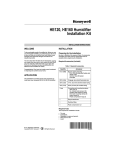
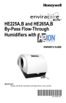
HE120A,B
By-Pass Drum Humidifier
INSTALLATION INSTRUCTIONS
WARNING
HUMIDIFIER
BYPASS
COLLAR
L
TA
ON
RIZ
HO
TEMPLATE
CAUTION
Freezing Water Hazard.
Can result in water damage to property.
Locate the humidifier where the ambient temperature is
between 32°F and 180°F (0°C and 93°C).
WN
DO O
FL
IMPORTANT
Template must be level before marking location.
1.
2.
3.
4.
OY
HB
HIG
Determine the best location for the humidifier and draw a
level line on the duct. See Fig. 1.
Tape this template in position and trace around it.
Remove the template and carefully cut the rectangular opening.
Position the humidifier housing (see Fig. 2) over the hole (be
sure it is level) and mark the five mounting holes.
TEMPLATE
Electrocution and Chemical Hazard.
Can cause death or blindness.
Do not cut or drill into any air conditioning line or electrical
accessory.
OY
WB
LO
M12248D
Fig. 1. Typical humidifier installation locations.
TEMPLATE
69-1104—3
COVER
BEARING END OF
DRUM SHAFT
12.
DRUM ASSEMBLY
Cut an opening for the 6 in. (152 mm) collar in the selected
by-pass location.
NOTE: Be sure to install a duct damper for summer shutoff if there
is air conditioning.
13.
14.
15.
16.
Install the 6 in. (152 mm) collar.
Use sheet metal screws to connect the by-pass tubing from
the collar to the humidifier.
Seal the connections with duct tape.
Insert the drain fitting in the bottom of the humidifier housing.
NOTE: Be sure the overflow tube is positioned toward the front,
on the same side as the by-pass tubing. The tubing should
not touch hot surfaces or sharp edges.
HUMIDIFIER
HOUSING
17.
18.
WATER PAN
WATER VALVE
OPENING
19.
20.
M12252
Fig. 2. Humidifier components.
5.
6.
7.
8.
9.
10.
Set the cabinet aside and drill the five 7/64 in. (3 mm) mounting holes.
Start the three 3/4 in. (19 mm) sheet metal screws in the top
holes.
Place the humidifier housing over the screws, level the housing and tighten the three screws.
Use two 1/2 in. (13 mm) screws to secure the humidifier
housing at the bottom.
On the inside of the humidifier housing where the by-pass
tube connects, snap the bearing bracket in place with the U
shape of the bracket pointing up.
Snap the motor plate into place on the opposite side of the
humidifier housing.
NOTE: Be sure the motor coupling is positioned toward the top.
11.
22.
23.
24.
25.
26.
27.
28.
NOTE: To raise the water level in the water pan, turn the valve
adjustment screw (located on the water valve inside the
humidifier) clockwise to lower it and counterclockwise to
raise it.
Place the lead wires through the hole in the bottom of the
motor cover and snap the cover in place.
69-1104—3
21.
Place the water pan in the humidifier housing so the overflow
tube is above the previously installed drain fitting.
Attach a 3/8 in. (10 mm) I.D. tubing to the drain fitting and
route continuously downward to a suitable drain, or catch
basin.
Screw the float onto the float valve assembly.
Attach the float valve to the humidifier housing on the same
side as the motor.
Insert the valve hole plug in the double D hole on the opposite side of the valve.
Assemble the drum and humidifier pad. See Fig. 3.
Insert the drum assembly into the motor coupling end and
snap into the bearing end.
Install the saddle valve (using the instructions on the saddle
valve bag) on the nearest cold water pipe.
Connect the copper tubing and route to the humidifier.
Connect the copper tubing to the humidifier valve and finger
tighten.
Use a 1/2 in. open end or adjustable wrench to tighten the
compression fitting securely.
Turn on the water at the saddle valve and adjust the water
level to 1-3/8 in. (35 mm) deep.
2
All wiring must comply with applicable local codes, ordinances and
regulations.
1.
2.
3.
SQUEEZE
SLIGHTLY
TO INSTALL
OPEN
DRUM END
CHECKOUT PROCEDURE
PAD
TINNERMAN
DRUM SHAFT
METAL TABS
CLOSED DRUM END
M12243
Fig. 3. Drum and humidifier pad assembly.
WIRING
CAUTION
Electrical Shock Hazard.
Can shock or burn out equipment.
• Disconnect power supply before installing or servicing.
• To prevent premature transformer burnout on multispeed
blower applications, do not wire the high voltage side of
the transformer to the same power source that services
the furnace blower.
After winter startup or maintenance, use the following procedure to
check the humidifier operation:
1. Turn on the humidifier power and water supply.
2. Check the water level in the humidifier water pan water level
setting should be 1-3/8 in. (35 mm). Turn the valve adjustment screw (located on the water valve inside the humidifier)
clockwise to lower the water level, and counterclockwise to
raise it.
3. Turn the Convertible Humidity Control to the highest setting,
or the H1008 Automatic Humidity Control to the Test position,
and set the thermostat to 10°F (6°C) above the room temperature.
4. Check that the humidifier pad is rotating.
5. Reset the thermostat and the Convertible Humidity Control to
a comfortable setting, or the Automatic Humidity Control to
the desired frost factor setting, for automatic operation.
Automation and Control Solutions
Honeywell International Inc.
Honeywell Limited-Honeywell Limitée
1985 Douglas Drive North
35 Dynamic Drive
Golden Valley, MN 55422
Scarborough, Ontario M1V 4Z9
customer.honeywell.com
® U.S. Registered Trademark
© 2006 Honeywell International Inc.
69-1104—3 C.H. Rev. 04-06
Mount the transformer in a convenient location.
Connect the wires to the 120V side of the transformer.
Wire the drum motor, transformer, and humidity Control.
Refer to the humidity Control installation instructions for
mounting and wiring information.