1
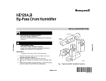
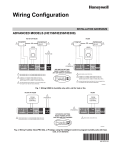
HE120, HE160 Humidifier
Installation Kit
INSTALLATION INSTRUCTIONS
WELCOME
INSTALLATION
To the comfortable world of humidified air. When you use
your Honeywell humidifier, you notice that your skin is not
as dry, and that your scratchy throat and irritated nasal
passages that aggravate allergies and asthma are
steadily improving.
Preparing for the Installation
You have also taken the first step in reducing the zapping
you create when you walk on your carpet and then touch
your TV, computer, metal door knob or your pet. Your
furniture and woodwork are also benefitting from the
difference that humidified air makes.
Required Accessories (Included)
Be sure to identify all the required (Table 1) accessories
(included) and make sure the appropriate tools are
available before beginning the installation.
Table 1. Required Accessories.
Congratulations! You have just made a great investment
in improving the comfort of your home.
Quantity
Accessory
6 ft (1.85M)
Bypass ducting including:
6 in. (155 mm) diameter flexible duct
Starter collar
Summer shut-off damper
Duct tape
20 ft (6.2m)
18 gauge, two-strand thermostat wire
20 ft (6.2m)
1/4 in. (6.35 mm) OD feed water tubing
10 ft (3.1m)
3/8 in (9.5 mm) ID overflow tubing
1 bag
Connecting and mounting hardware:
Wire nuts (4)
No. 8 sheet metal screws (18)
Overflow tube clamps (2 sizes)
Feed tube mounting clamps (6)
Brass inserts (2)
Plastic compression rings (2)
1
Plug-in transformer
1
Overflow fitting
1
Plastic compression nut
APPLICATION
This installation kit contains all the parts necessary to
install your new Honeywell HE120 or HE160 Humidifier.
Required Tools
Tools required for installation include:
•
•
•
•
•
® U.S. Registered Trademark
Copyright © 2001 Honeywell •
•All Rights Reserved
Tin snip.
Screwdriver.
Adjustable or open-end wrench.
Drill, punch or awl.
Level.
69- 1571
HE120, HE160 HUMIDIFIER INSTALLATION KIT
Determining Best Location for Humidifier
For return duct mounting, the humidistat should be
mounted upstream from the humidifier or bypass so that
it is properly sensing the relative humidity of the living
space. Locate the control at least 8 in. (203 mm)
upstream from the humidifier in the return air duct. (See
Fig 2.)
• Select a location for the humidifier on the supply
(warm air stream) or the return plenum. See Fig. 1.
• Select a location for the bypass on the opposite
plenum. The humidifier is designed to allow bypass
duct mounting on either side of the humidifier.
• Select a location that cannot damage the air
conditioner A-coil during installation.
• Select a location where the 6 ft (1.86m) of 6 in. (155
mm) duct provided is adequate to connect the
humidifier to the bypass.
— Do not locate the humidifier or bypass on a furnace body.
— Allow adequate clearance in front of and above
the humidifier so you can easily remove the cover
to perform routine maintenance.
— Mount humidifier at least 3 in. (78 mm) above the
furnace body to allow adequate space for the
drain or overflow line.
— Mount humidifier in a conditioned space to prevent freezing.
ALTERNATE LOCATION
RETURN
AIR
6 in. (152 mm)
MINIMUM
RETURN
AIR
15 in. (381 mm)
MINIMUM
BEST
LOCATION
RETURN AIR DUCT
M12831
Fig. 2. Selecting duct location for humidistat.
Locating Closest 120V Electrical Outlet
• Select location with access to an outlet. If not
available, contact an electrician to have one installed.
• Make sure that the 20 ft (6.2m) of thermostat wire is
adequate to reach from the humidifier motor to the
humidistat, to the plug-in transformer in the outlet.
L
A
NT
O
RIZ
HO
OY
HB
HIG
INSTALLING HUMIDIFIER
WARNING
WN
DO O
FL
Hazardous Voltage.
Can cause personal injury or equipment
damage.
Do not cut or drill into any air conditioning or
electrical accessory.
Y
BO
W
LO
M12248C
CAUTION
Fig. 1. Typical humidifier installation locations.
Sharp Edges Installation Hazard.
Can cause personal injury.
Wear gloves and safety glasses.
Selecting Water Supply Location
• Use either hard or soft water in the humidifier and
either hot or cold water.
• Make sure that the 20 ft (6.2m) of feed water tubing
provided is adequate to connect the water supply
(saddle valve) with the humidifier float valve.
1.
2.
3.
Locating Closest Floor Drain (If Available)
• Select location with access to a floor drain (if
available); floor drain is optional for safety overflow.
• Make sure that the 10 ft (3.1m) of overflow tubing is
adequate to reach from the humidifier overflow
connection to the floor drain.
4.
5.
6.
Selecting Location for Humidistat
Select a location for the humidistat on the return plenum
or on the wall in the living space.
NOTE: Sidecaps are interchangeable for either left or
right bypass installation. See device installation
instructions.
NOTE: Mounting on the return plenum is the easiest
installation for the control circuit wiring.
69-1571
Turn off power to the air handing system at the circuit breaker.
Draw a level line on the plenum in the location
chosen for the humidifier. (Leveling assures optimal humidifier performance.)
Locate the template in the Humidifier Installation
Instructions.
Tape the template in position and trace around the
template.
Remove the template and carefully cut the rectangular opening.
Disassemble the humidifier; remove the cover and
take out the disk or drum assembly. See Fig. 4 or
5.
NOTE: For HE120, go to step 7. For HE160, go to step
13.
2
HE120, HE160 HUMIDIFIER INSTALLATION KIT
Position the HE120 Humidifier base in the opening,
mark the five screw holes, and pre-drill the screw
holes.
8. Insert the three 3/4 in. (19 mm) sheet metal screws
into the top holes.
9. Hang the humidifier over the screws and secure
with the two remaining 1/2 in (13 mm) screws.
10. Inside the humidifier housing, where the bypass
tube connects, snap the bearing bracket into place
with the U-shape of the bracket pointing up.
11. Snap the motor plate into place on the opposite
side of the humidifier housing.
7.
DISK WHEEL
NOTE: Be sure the motor coupling is positioned toward
the top,
12. Place the lead wires through the hole in the bottom
of the motor cover and snap the cover into place.
NOTE: For HE120, go to Connecting Plumbing section.
For HE160, go to step 13.
13. Hold the hanger bracket against the duct/plenum
so the bottom of the hanger bracket is about 1/2 in.
(13 mm) from the top edge of the duct/plenum
opening. Ensure that it is level and mark the three
mounting bolt locations (Fig. 3A).
14. Drill three 3/16 in. (5 mm) holes in the duct/plenum
(Fig. 3B).
15. Mount the hanger bracket on the inside of the duct/
plenum using the 3/16 in. (5 mm) machine screws
and nuts provided (Fig. 3C).
DRAIN CAP
A. HOLD HANGER
LEVEL AND MARK
BOLT HOLE
LOCATIONS
B. DRILL HOLES
M20221
Fig. 4. Disassembling disk humidifier.
NOTE: Hanger can be lowered up to 3/4 in. (19 mm) to
accommodate larger pre-existing holes.
1/2 IN.
FLOAT
VALVE
COVER
BEARING END OF
DRUM SHAFT
DRUM
ASSEMBLY
C. INSTALL HANGER
BRACKET
INSIDE
PLENUM/DUCT
M20220
Fig. 3. Mounting HE160 on plenum.
HUMIDIFIER HOUSING
16. Hang the basin from the mounting hanger and
secure with the sheet metal screws provided.
17. Insert the screws into the pilot holes and through to
the back of the bracket.
18. Snap the motor plate and inlet into the basin. Be
sure the tabs fit into the corresponding basin slots.
19. Install the drain and cap at the bottom of the basin,
with the cap on the outside of the humidifier housing. Hand-tighten until the drain does not turn; do
not overtighten.
WATER PAN
WATER VALVE OPENING
M12252
Fig. 5. Disassembling drum humidifier
CONNECTING PLUMBING
1.
Install the float into the slot in the side of the basin.
Hand-tighten the nut.
NOTE: For HE120, attach the float on the same side as
the motor; install the plug in the opposite slot.
2.
3
Shut off the water. (Either hot or cold water and
either hard or softened water can be used in the
humidifier.)
69-1571
HE120, HE160 HUMIDIFIER INSTALLATION KIT
d. Insert the tubing into the float valve fitting and
support the valve while tightening the compression nut.
CAUTION
Chemical Hazard.
Can cause personal injury or equipment
damage.
Do not use any line connected to an air
conditioner.
Do not use gas line.
3.
NOTE: Do not over-tighten the compression nut. Moderate tightness prevents leaking.
e. Repeat steps a. through d. for saddle valve fitting.
f. Secure tubing with clamps provided.
Use the self-piercing saddle valve (included) to tap
into the water supply line at the location selected.
See Fig. 6. If tapping into galvanized pipe, drain
line and pre-drill 3/16 in. tap for saddle valve.
BRASS COMPRESSION NUT
PLASTIC
COMPRESSION RING
NOTE: The saddle valve is not designed to regulate
water flow. The valve is either open or closed.
BRASS INSERT
IMPORTANT
To prevent debris from clogging the solenoid inline filter, be sure to install the saddle valve handle pointing toward the ceiling.
SCREW DRIVER
M20176
WATER LINE
Fig. 7. Installing feed tubing.
5.
NOTE: Be sure to install water pan with overflow positioned over fitting.
M20175
b. Slide the overflow clamp over the tubing.
c. Push the tubing over the overflow fitting on the
humidifier.
d. Hand-tighten the clamp around the tubing to
secure the overflow tubing.
e. Fasten the overflow tubing (can use duct tape)
along the route to prevent movement and
ensure downward slope for correct drainage.
Fig. 6. Installing saddle valve.
4.
Use 1/4 in. (6 mm) OD tubing and connect saddle
valve to float valve (see Fig. 7).
NOTE: For HE120, use plastic compression nut for float
connection.
a. Place compression nut over tubing.
NOTE: Cut tubing to correct length so the tubing terminates at the drain or bucket.
NOTE: For HE160, use brass expander insert for float
connection.
Adjusting HE160 Water Level (Fig. 8)
b. Install brass insert into end of tubing.
1.
2.
3.
NOTE: A compression ring is required only at the tub
end connected to the saddle valve.
c. Slide the plastic compression ring over the
tubing. (Discard copper compression ring provided with valve.)
4.
5.
6.
NOTE: To prevent leaking, use plastic (Delrin) sleeve
rings with plastic tubing. Use copper sleeve
rings only with copper tubing.
69-1571
Connect a 3/8 in. (10 mm) overflow tube to the
humidifier overflow fitting and run to the floor drain
or bucket if floor drain is not available.
a. Insert overflow fitting. (HE160 fitting is provided
in the kit. HE120 fitting is provided with humidifier; position it in hole opposite of float.)
4
Test fit the disk assembly in the humidifier.
Turn on the water supply and check for leaks.
Adjust the float assembly so the water height just
covers the disks; verify that the water is within the
range of the textured bands inside the basin.
Adjust the float, as necessary.
Secure the float adjustment nut with a 9/16 in.
(15 mm) wrench.
Remove the disk and drain the water before beginning the bypass installation.
HE120, HE160 HUMIDIFIER INSTALLATION KIT
ENSURE TABS ON INLET AND
MOTOR PLATE FIT INTO
SLOTS IN LID FLANGES
SUMMER
WINTER
WATER
OVERFLOW HOLE
M20173
FLOAT ADJUSTMENT SLOT
M20222
Fig. 10. Installing starter collar.
Fig. 8. Adjusting HE160 water level.
4.
INSTALLING BYPASS
1.
2.
5.
Use inside of the 6 in. (155 mm) starter collar as a
template to mark the opening for the bypass.
Carefully cut the 6 in. (155 mm) opening for the
starter collar. See Fig. 9. Use a drill, punch or awl
to start the cut in the middle of the circle. Cut in an
outward spiral to assist in controlling the cut.
Remove liner to expose foam adhesive. Position
starter collar over opening.
Using sheet metal screws, connect starter collar to
the duct and bypass duct from humidifier to starter
collar. Be sure to secure the collar to the duct with
sheet metal screws. See Fig. 11.
6 IN. ROUND TEMPLATE
STARTING
HOLE
M20223
Fig. 11. Connecting bypass ducting.
IMPORTANT
To avoid sagging and stress on humidifier, add
support if ducting is longer than 4 ft (1.25m).
M20172
Fig. 9. Cutting bypass opening.
3.
6.
7.
Assemble the summer shutoff damper into the
starter collar. Verify that the damper rotates freely
between the open and closed positions. Make sure
handle will be accessible. Mark the damper closed
position as summer and the open position as winter. See Fig. 10.
8.
5
Seal the duct connections with duct tape.
Reinstall the humidifier drum or disk assembly in
the humidifier housing.
Install the humidifier lid.
69-1571
HE120, HE160 HUMIDIFIER INSTALLATION KIT
INSTALLING HUMIDISTAT
HUMIDISTAT
Mounting Duct
1.
2.
3.
4.
5.
6.
7.
OUTDOOR
Humidity Control
Régulateur d'humidité
Apply the template to the duct location chosen for
the humidistat. Make sure the template is level
before drilling the holes.
Refer to the template (provided with the H8909
Humidistat Installation Instructions) to drill the control assembly opening and mounting holes for the
H8908.
Remove the H8908 case from the base.
Position the foam gasket on the H8908 base.
Position the base on the duct with the arrow up.
Secure the base to the duct using the four
1 in. (25 mm) mounting screws provided with humidistat.
Connect the low-voltage wires to the leads and
replace the H8908 case. See Fig. 12.
HUMIDIFIER
DRIVE
MOTOR
Fig. 13. Wiring the controls.
1.
Run the two-strand thermostat wire from the
humidifier to the transformer, from the transformer
to the humidistat.
Cut lengths of thermostat wire to reach between
components, leaving adequate wire at both ends
for connections.
NOTE: Transformer and humidistat can be wired in any
order.
3.
4.
5.
At the humidifier, connect the black and white conductors to the two motor leads.
At the transformer, connect both black conductors
to the two transformer terminals. Use a wire nut to
connect the white conductors.
At the humidistat, connect the black and white conductors to the two humidistat terminals.
TESTING HUMIDIFIER OPERATION
M20179
Checklist
Fig. 12. Humidistat base and rear view.
❑
❑
❑
❑
❑
❑
❑
WIRING
CAUTION
Hazardous Voltage.
Can cause personal injury or equipment
damage.
Disconnect power supply before installing or
servicing equipment.
Humidifier is level.
Starter collar is secured with sheet metal screws.
Summer shut-off damper is open (in winter position).
Control wiring was reviewed using circuit diagram.
Transformer is plugged in.
Feed line has no kinks.
Overflow line slopes continuously down and ends at
floor drain or bucket.
After installation use the following steps to check the
humidifier operation:
1. Turn on the power and the water supply.
IMPORTANT
All wiring must comply with applicable local
code, ordinances and regulations.
NOTE: For HE160, see Adjusting Water Level section.
2.
Wire the humidifier motor, humidistat and transformer.
See Fig. 13.
69-1571
BLACK
WHITE
M20224
REAR OF HUMIDISTAT
HUMIDISTAT WIRES
BLACK
WHITE
2.
WIRE SLOT
HUMIDITY
SETTING
15%
20%
25%
30%
35%
40%
TRANSFORMER
NOTE: For wall mounting instructions, see the H8908
Installation Instructions.
HUMIDISTAT BASE
TEMPERATURE
-30 ¡C
-20 ¡F
-25 ¡C
-10 ¡F
-20 ¡C
0 ¡F
-10 ¡C
+10 ¡F
-5 ¡C
+20 ¡F
Over 0 ¡C
Over 20 ¡F
3.
4.
5.
6.
6
Verify that basin fills and float shuts off before
water enters overflow tubing.
Turn the H8908 Humidity Control to On.
Make sure that drum or disk turns.
Check for leaks.
Reset the H8908 Humidity Control to a comfortable
setting for automatic operation.
HE120, HE160 HUMIDIFIER INSTALLATION KIT
TROUBLESHOOTING YOUR HUMIDIFIER (TABLE 2)
Table 2. Troubleshooting Humidifier.
Problem
Water leakage
No water to basin.
What to look for
What to do
Leaking joints
Shut off water.
Tighten connections.
Brass tubing inserts
Verify that brass tubing inserts are used.
Saddle valve leaking
Verify rubber pad is installed on saddle valve.
Electrical
Verify control circuit wiring.
Check all connections.
Humidistat
Turn humidistat up and down and listen for contact to
click.
Transformer
Verify that outlet has power.
Verify plumbing connections.
Check for kinks.
Plumbing
Saddle valve
Verify that needle pierced water line and then back
out needle to open valve.
Float valve
Remove cover and verify that float is moving freely.
Air leakage
Check duct joints
Seal with duct tape.
Water flowing into
overflow
Device level
Level device.
Float valve
Check for free movement of float arm.
Adjust water level of float.
7
69-1571
HE120, HE160 HUMIDIFIER INSTALLATION KIT
Home and Building Control Home and Building Control
Honeywell
1985 Douglas Drive North
Golden Valley, MN 55422
69-1571 G.H. 09-01
Honeywell Limited-Honeywell Limitée
35 Dynamic Drive
Scarborough, Ontario
M1V 4Z9
Printed in U.S.A. on recycled
paper containing at least 10%
post-consumer paper fibers.
www.honeywell.com/yourhome