1
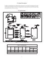
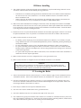
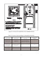
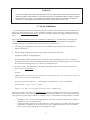
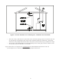
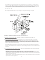
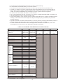
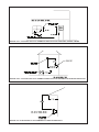
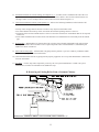
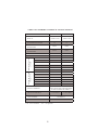
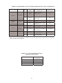
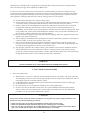
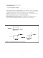
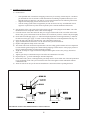
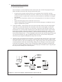
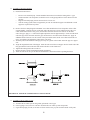
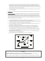
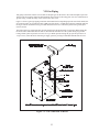
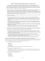
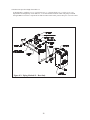
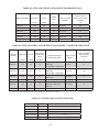
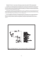
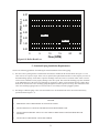
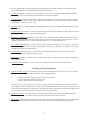
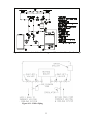
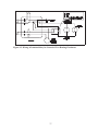
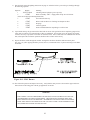
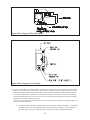
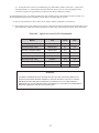
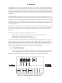
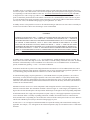
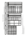
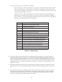
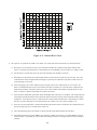
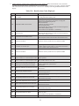
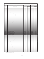
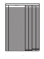
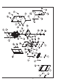
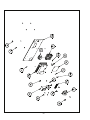
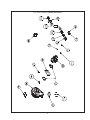
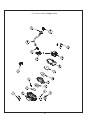
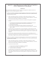
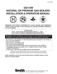
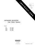
D
E S I G N E D
T O
L
E A D
BWC Series
High Efficiency Gas-Fired Hot Water
Direct Vent Condensing Boilers
Installation Instructions
These instructions must be affixed on or adjacent to the boiler.
Models:
• BWC150
• BWC225
Warning: Improper installation, adjustment, alteration,
service or maintenance can cause property damage, injury,
or loss of life. For assistance or additional information, consult a qualified installer, service agency or the gas supplier.
This boiler requires a special venting system. Read these
instructions carefully before installing.
Manufacturer of Hydronic Heating Products
P.O. Box 14818 3633 I. Street
Philadelphia, PA 19134
www.crownboiler.com
Table of Contents
I.Product Description2
II. Specifications 2
III.Before Installing3
IV. Locating The Boiler 3
V.Air For Ventilation5
VI.Venting7
Vent System Design7
Removing An Existing Boiler From Common Chimney 14
Vent/Intake System Assembly 14
VII.Gas Piping23
VIII. System Piping 24
General System Piping Precautions 24
System Design 24
Standard Piping Installation Requirements 31
Piping For Special Situations32
IX. Wiring 34
X. Start-up and Checkout 38
XI. Operation 44 XII. Service and Maintenance 49
XIII. Troubleshooting 51
XIV.
Parts55
Appendix A Special Requirements For Side-Wall
69
Vented Appliances In The Commonwealth
of Massachusetts
1
I Product Description
The BWC is an aluminum gas fired condensing boiler designed for use in forced hot water heating systems requiring supply water temperatures of 180°F or less. This boiler may be vented vertically or horizontally with combustion air supplied from outdoors. This boiler is not designed for use in gravity hot water systems or systems containing significant amounts of dissolved oxygen.
II Specifications
Figure 2.1: General Configuration
Table 2.2: Specifications
MODEL*
NO. OF
SECTIONS
D.O.E.
MAXIMUM MINIMUM
AHRI NET
HEATING
INPUT
INPUT
RATING
CAPACITY
(BTU/hr)
(BTU/hr)
(BTU/hr)
(BTU/hr)
VENT COLLAR
DIAMETERS (IN.)
INLET
EXHAUST
BWC150
3
150,000
50,000
133,000
117,000
4
3
BWC225
4
225,000
75,000
202,000
176,000
4
4
* MODELS SHOWN ARE FOR NATURAL GAS. ADD “LP” SUFFIX TO MODEL NUMBER SHOWN FOR PROPANE MODEL NUMBER (ie BWC225LP).
PERFORMANCE RATINGS ARE THE SAME FOR BOTH FUELS.
2
III Before Installing
1) Safe, reliable operation of this boiler depends upon installation by a professional heating contractor in strict
accordance with this manual and the authority having jurisdiction.
•
•
In the absence of an authority having jurisdiction, installation must be in accordance with this manual and the National Fuel Gas Code, ANSI Z223.1. In Canada, installation must be in accordance with the B149.1 Installation Code
Where required by the authority having jurisdiction, this installation must conform to the Standard for Controls and Safety Devices for Automatically Fired Boilers (ANSI/ASME CSD-1).
2) BWC boilers utilize aluminum heat exchangers constructed, tested, and stamped in accordance with ASME Boiler and Pressure Vessel Code Case 2382-2. Some jurisdictions which require ASME boiler construction do
not recognize this Code Case and may not approve the installation of an aluminum boiler. Consult the authority having jurisdiction before installing this boiler.
3) Read Section VI to verify that the maximum combustion air and exhaust pipe lengths will not be exceeded in
the planned installation. Also verify that the vent terminal can be located in accordance with Section VII.
4) Make sure that the boiler is correctly sized:
•
•
•
•
For heating systems employing convection radiation (baseboard or radiators), use an industry accepted
sizing method such as the I=B=R Guide RHH published by the Air-Conditioning, Heating and Refrigeration Institute (AHRI).
For new radiant heating systems, refer to the radiant tubing manufacturer’s boiler sizing guidelines.
For systems including a Crown Mega-Stor indirect water heater, size the boiler to have either the DOE
Heating Capacity required for the Mega-Stor or the net rating required for the heating system, whichever
results in the larger boiler.
For systems that incorporate other indirect water heaters, refer to the indirect water heater manufacturer’s
instructions for boiler output requirements.
5) Make sure that the boiler received is configured for the correct gas (natural or LP).
6) Make sure that the boiler is configured for use at the altitude at which it is to be installed.
NOTICE
This product must be installed by a licensed plumber or gas fitter when installed within the
Commonwealth of Massachusetts. See Appendix A for additional important information about
installing this product within the Commonwealth of Massachusetts.
IV Locating the Boiler
1) Observe the minimum clearances shown in Figure 4.1. These clearances apply to both combustible and noncombustible materials. Observe the minimum clearances to combustibles for vent pipe shown in Table 4.2.
2) Note the recommended service clearances in Figure 4.1. The recommended service clearances may be reduced to the minimum combustible clearances with the understanding that servicing the boiler will become
increasingly difficult as the clearance is reduced.
3) Boiler may be installed on non-carpeted combustible surface.
4) The relief valve must be installed in the factory specified location.
5) The boiler should be located so as to minimize the length of the vent system.
6) The combustion air piping must terminate where outdoor air is available for combustion and away from areas
that will contaminate combustion air. Avoid areas near chemical products containing chlorine, chloride based
salts, chloro/fluorocarbons, paint removers, cleaning solvents and detergents.
3
Figure 4.1: Clearances To Combustible Or Non-combustible Material
Table 4.2: Clearances From Vent Piping To Combustible Construction
TYPE OF VENT PIPE
PIPE DIRECTION
ENCLOSURE
HEAT FAB SAF-T VENT
PROTECH FASNSEAL
Z-FLEX Z-VENT III
METAL-FAB CORR-GUARD
VERTICAL OR
HORIZONTAL
AT LEAST ONE SIDE OPEN,
COMBUSTIBLE MATERIAL ON A
MAXIMUM OF THREE SIDES
HEAT FAB SAF-T VENT
PROTECH FASNSEAL
Z-FLEX Z-VENT III
METAL-FAB CORR-GUARD
HORIZONTAL OR VERTICAL
WITH OFFSETS
ENCLOSED ON ALL FOUR SIDES
HEAT FAB SAF-T VENT
PROTECH FASNSEAL
Z-FLEX Z-VENT III
METAL-FAB CORR/GUARD
VERTICAL WITH NO OFFSETS
ENCLOSED ON ALL FOUR SIDES
4
MINIMUM CLEARANCE
TO COMBUSTIBLE
MATERIAL
1”
2-1/2”
2-1/2”
WARNING
OUTDOOR COMBUSTION AIR MUST BE PIPED TO THE AIR INTAKE. NEVER PIPE COMBUSTION
AIR FROM AREAS CONTAINING CONTAMINATES SUCH AS SWIMMING POOLS AND LAUNDRY
ROOM EXHAUST VENTS. CONTAMINATED COMBUSTION AIR WILL DAMAGE THE BOILER
AND MAY CAUSE PROPERTY DAMAGE, PERSONAL INJURY OR LOSS OF LIFE.
V Air for Ventilation
Air for combustion must always be obtained directly from outdoors, however sufficient air for ventilation must
still be provided in the boiler room. Air for ventilation is required to keep various boiler components from overheating and is always obtained from indoors. To ensure an adequate ventilation air supply, perform the following
steps:
Step 1: Determine whether the boiler is to be installed in a confined space - A confined space is defined by the
National Fuel Gas Code as having a volume less than 50 cubic feet per 1000 BTU/hr input of all appliances
installed in that space. To determine whether the boiler room is a confined space:
1) Total the input of all appliances in the boiler room in thousands of BTU/hr. Round the result to the next
highest 1000 BTU/hr.
2) Find the volume of the room in cubic feet. The volume of the room in cubic feet is:
Length (ft) x width (ft) x ceiling height (ft)
In calculating the volume of the boiler room, consider the volume of adjoining spaces only if no doors are
installed between them. If doors are installed between the boiler room and an adjoining space, do not consider
the volume of the adjoining space, even if the door is normally left open.
3) Divide the volume of the boiler room by the input in thousands of BTU/hr. If the result is less than 50, the
boiler room is a confined space.
Example:
A BWC225 and a water heater are to be installed in a room measuring 6ft – 3 in x 7ft with an 8 ft ceiling. The
water heater has an input of 30000 BTU/hr:
Total input in thousands of BTU/hr = (225000 BTU/hr + 30000 BTU/hr) / 1000 = 255 MBTU/hr
Volume of room = 6.25 ft x 7 ft x 8 ft = 350 ft3
350/255 = 1.37. Since 1.37 is less than 50, the boiler room is a confined space.
Step 2a: If the boiler is to be placed in a confined space, provide two openings into the boiler room, one near the
floor and one near the ceiling. The top edge of the upper opening must be within 12” of the ceiling and the bottom
edge of the lower opening must be within 12” of the floor (Fig 5.1). The minimum opening dimension is 3 inches.
•
•
If the BWC boiler is the only gas-burning appliance in the boiler room, these openings must each have a
minimum free area of 100 square inches.
If other gas-burning appliances are in the boiler room, size the openings in accordance with the appliance
manufacturer’s instructions or the National Fuel Gas Code. Minimum opening free area is 100 square
inches even if opening requirements for other appliances are less.
5
Figure 5.1: Boiler Installed In A Confined Space, Ventilation Air From Inside
•
•
If the total volume of both the boiler room and the room to which the openings connect is less than 50 cubic feet
per 1000 BTU/hr of total appliance input, install a pair of identical openings into a third room. Connect additional rooms with openings until the total volume of all rooms is at least 50 cubic feet per 1000 BTU/hr of input.
The “free area” of an opening takes into account the blocking effect of mesh, grills, and louvers. Where screens
are used, they must be no finer than ¼” (4 x 4) mesh.
Step 2b: If the boiler is to be placed in an unconfined space the natural infiltration into the boiler room will provide adequate air for ventilation without additional openings into boiler room.
6
VI Venting
WARNING
Failure to vent this boiler in accordance with these instructions could result in unreliable boiler
operation, severe damage to the boiler or property, or unsafe operation:
* Use only vent systems and materials explicitly permitted by Crown for use with this boiler.
* Do not attempt to mix components from different approved vent systems.
* Do not obtain combustion air from within the building.
* Do not install a barometric damper or drafthood on this boiler.
* Do not attempt to use the vent system for this boiler with any other appliance.
* Moisture and ice may form on the surfaces around the vent termination. To prevent deterioration, surfaces should be in good repair (sealed, painted, etc.)
A. Vent System Design
There are two basic ways to vent the BWC boiler:
• Horizontal (“side wall”) Venting - Vent system exits the building through an outside wall. Combustion air is
obtained through a separate pipe from outside.
• Vertical Venting - Vent system exits the building through a roof. Combustion air is obtained through a separate
pipe from outside.
A description of each of these venting options is listed in Tables 6.2a and 6.2b. For clarity, these vent options are numbered from 1 to 7. One of the vent option columns in Table 6.2 must match the planned vent and air intake system exactly. In addition, observe the following guidelines:
1) Approved vent systems - Use only one of the approved vent systems shown in Table 4. These systems are made of a
special stainless steel alloy (AL29-4C) for protection against corrosive flue gas condensate. They are also designed
to provide a gas tight seal at all joints and seams so that flue gas does not enter the building. Each approved vent
system has a unique method for installation - do not attempt to mix components from different vent systems.
2) Maximum Vent and Air Intake Lengths - The maximum length of the vent air intake piping depends upon the vent
option selected and the boiler size. See Table 6.2 for the maximum vent length. In addition to the maximum length
of piping shown in Table 6.2, the following fittings may also be used:
•
•
•
•
Horizontal Vent Systems: One 90 deg. elbow
Horizontal Air Intake Systems: One 90 deg. elbow
Vertical Vent Systems: Two 90 deg. elbows
Vertical Air Intake Systems: Two 90 deg. elbows
If additional elbows are desired, the maximum allowable vent length must be reduced by the amount shown in Table
6.6 for each additional elbow used. Termination fittings are not counted when counting additional elbows.
Example:
A 3” vent system is planned for a horizontally vented BWC150 which has the following components:
2 ft vertical pipe
1 90 elbow
5 ft horizontal pipe
1 90 elbow
3 ft horizontal pipe
1 45 elbow
4 ft horizontal pipe
1 termination elbow
7
The Vent Option #1 column in Table 6.2a describes a horizontal direct vent system using 3” vent pipe. From this
column, we see that a BWC150 may have a vent length of up to 55ft. The first 90 elbow and the termination elbow
are not considered. From Table 6.6, the equivalent length of the 3” 45 elbow is 4ft and the equivalent length of the
3” 90 degree elbow is 5.5ft. The maximum allowable run of straight pipe on this system is therefore:
55ft – 4 ft – 5.5ft = 40ft
Since the planned installation has only 14 ft of straight pipe, the planned vent length is acceptable.
FIGURE 6.1: HORIZONTAL DIRECT VENTING (VENT OPTIONS 1,2)
3) Minimum Vent and Air Intake Lengths - Minimum vent length is 2ft. Minimum air inlet length is 2ft.
4)
Permitted Terminals for Horizontal Venting (Vent Options 1,2) - The vent terminal is either a tee or an elbow
supplied by the vent system manufacturer and equipped with a rodent screen. Vent system manufacturer’s part
numbers for these fittings are shown in Table 6.5. In some cases, the elbows and tees shown in Table 6.5 require
separate rodent screens. When this is the case, vent manufacturer part numbers for these additional parts are shown
in Table 6.5 along with the termination fitting.
The air intake fitting on a horizontal vent systems is always a 90 degree elbow with a rodent screen. This elbow is
made out of the same material as the rest of the air inlet system (either galvanized or PVC) and is installed as shown
in Figure 6.1.
5)
Horizontal Vent and Air Intake Terminal Location - Observe the following limitations on the vent terminal location
(also see Figure 6.3):
• Vent terminals must be at least 1 foot from any door, window, or gravity inlet into the building.
• Maintain the correct clearance and orientation between the vent and air intake terminals. The vent and air intake
terminals must be at the same height and their center lines must be between 12 and 36 inches apart. Both terminals
must be located on the same wall.
• The bottom of the vent and air intake terminals must be at least 12” above the normal snow line. In no case should
they be less than 12” above grade level.
8
•
•
•
•
•
•
•
•
•
•
The bottom of the vent terminal must be at least 7 feet above a public walkway.
Do not install the vent terminal directly over windows or doors.
The bottom of the vent terminal must be at least 3 feet above any forced air inlet located within 10 feet.
USA Only: A clearance of at least 4 feet horizontally must be maintained between the vent terminal and gas
meters, electric meters, regulators, and relief equipment. Do not install vent terminal over this equipment. In
Canada, refer to B149.1 Installation Code for clearance to meters, regulators and relief equipment.
Do not locate the vent terminal under decks or similar structures.
Top of vent terminal must be at least 5 feet below eves, soffits, or overhangs. Maximum depth of overhang is 3 ft.
Vent terminal must be at least 6 feet from an inside corner.
Under certain conditions, water in the flue gas may condense, and possibly freeze, on objects around the terminal
including on the structure itself. If these objects are subject to damage by flue gas condensate, they should be
moved or protected.
If possible, install the vent and air intake terminals on a wall away from the prevailing wind. Reliable operation of
this boiler cannot be guaranteed if the terminal is subjected to winds in excess of 40 mph.
Air intake terminal must not terminate in areas that might contain combustion air contaminates, such as near
swimming pools. See Section IV for more information on possible contaminates.
TABLE 6.2a: SUMMARY OF HORIZONTAL VENTING OPTIONS
VENT OPTION #
1
CLASSIFICATION USED IN THIS
MANUAL
HORIZONTAL
DIRECT VENT
HORIZONTAL
DIRECT VENT
6.1
6.1
VENT PIPE STRUCTURE
PENETRATION
WALL
WALL
AIR INTAKE PIPE STRUCTURE
PENETRATION
WALL
WALL
VENT PIPE SIZE
3”
4”
AIR INTAKE PIPE SIZE
4”
4”
MAXIMUM INTAKE
PIPE LENGTH
MAXIMUM VENT PIPE
LENGTH
ILLUSTRATED IN FIGURE
2
BWC150
55 FT
N.R.
BWC225
N.R.
55 FT
BWC150
60 FT
N.R.
BWC225
N.R.
60 FT
EXHAUST TERMINAL
3” 90 ELBOW
OR TEE
4” 90 ELBOW
OR TEE
AIR INTAKE TERMINAL
4” 90 ELBOW
4” 90 ELBOW
APPROVED VENT SYSTEM
SHOWN IN TABLE 6.5
VENT MATERIAL
AIR INTAKE MATERIAL
“N.R” - Not recommended
“N.A.” - Not applicable
GALVANIZED OR PVC
9
3
(RESERVED
FOR FUTURE
USE)
4
(RESERVED
FOR FUTURE
USE)
5
(RESERVED
FOR FUTURE
USE)
FIGURE 6.3a: LOCATION OF VENT TERMINAL RELATIVE TO WINDOWS, DOORS, GRADE
FIGURE 6.3b: LOCATION OF VENT TERMINAL RELATIVE TO METERS AND FORCED AIR INLETS
FIGURE 6.3c: POSITIONING VENT TERMINAL UNDER OVERHANGS
10
6)
Permitted Terminals for Vertical Venting (Vent Options 6, 7) - A rodent screen is installed in the end of the vent
pipe. Vent manufacturer part numbers for these screens are shown in Table 4. The air inlet terminal consists of a
180 degree elbow (or two 90 degree elbows) with a rodent screen as shown in Figure 6.4.
7) Vertical Vent Terminal Locations (Vent Options 6,7) - Observe the following limitations on the location of all
vertical vent terminals (see Figure 6.4):
• The top of the vent pipe must be at least 2 feet above any object located within 10 feet.
• The vertical distance between top of the vent and air inlet terminal openings must be at least 12”.
• The bottom of the air inlet terminal must be at least 12” above the normal snow accumulation that can be expected
on the roof.
• The air intake terminal must be located on the roof and must be no further than 24” horizontally from the exhaust
pipe.
8) Wall thimbles – Wall thimbles are required where the vent pipe passes through combustible walls with less than
the required clearance shown in Table 4.2 or as required by local codes. Vent manufacturer’s wall thimble part
numbers are shown in Table 6.5.
9) Pitch of Horizontal piping – All horizontal vent piping must be pitched ¼” per foot so that any condensate which
forms in this piping will run towards the boiler.
10) Vertical and horizontal sections of piping must be properly supported. See vent system manufacturer’s instructions
for more information.
11) Fire Stops – Use fire stops where required by code or by the vent system manufacturer. Consult vent system
manufacturer’s literature for information on suitable fire stops.
B. Removing an Existing Boiler From a Common Chimney
FIGURE 6.4: VERTICAL DIRECT VENT SYSTEM (VENT OPTIONS 6, 7)
11
TABLE 6.2b: SUMMARY OF VERTICAL VENTING OPTIONS
VENT OPTION #
6
CLASSIFICATION USED IN THIS
MANUAL
VERTICAL
DIRECT VENT
VERTICAL
DIRECT VENT
6.4
6.4
VENT PIPE STRUCTURE
PENETRATION
ROOF
ROOF
AIR INTAKE PIPE STRUCTURE
PENETRATION
ROOF
ROOF
VENT PIPE SIZE
3”
4”
AIR INTAKE PIPE SIZE
4”
4”
MAXIMUM INTAKE
PIPE LENGTH
MAXIMUM VENT PIPE
LENGTH
ILLUSTRATED IN FIGURE
7
BWC150
49.5 FT
N.R.
BWC225
N.R.
47 FT
BWC150
52 FT
N.R.
BWC225
N.R.
52 FT
RODENT SCREEN BY VENT SYSTEM
MANUFACTURER. SAME DIAMETER
AS VENT SYSTEM. SEE TABLE 6.5.
EXHAUST TERMINAL
AIR INTAKE TERMINAL
4” 180 ELBOW
VENT MATERIAL
APPROVED VENT SYSTEM SHOWN
IN TABLE 6.5
AIR INTAKE MATERIAL
“N.R” - Not recommended
4” 180 ELBOW
GALVANIZED OR PVC
“N.A.” - Not applicable
12
TABLE 6.5: PERMISSIBLE VENT SYSTEMS AND PRINCIPLE VENT COMPONENTS
MANUFACTURER
HEAT FAB
VENT SYSTEM
SAF-T VENT
EZ SEAL
PROTECH
SYSTEMS
INC.
FASNSEAL
Z-FLEX
SVE
SERIES III
(“Z-VENT III”)
METAL-FAB
SIZE
WALL
THIMBLES
3
7393GC
7393GCS
5391CI
4
7493GC
7493GCS
5491CI
3
FSWT3
ELBOW: FSELB9003 + FSBS3
TEE: FSTT3
FSBS3
4
FSWT4
ELBOW: FSELB9004 + FSBS4
TEE: FSTT4
FSBS4
3
2SVSWTEF03
ELBOW: 2SVSTEX0390
TEE: 2SVSTTF03
24SVSTPF03
4
2SVSWTEF04
ELBOW:
2SVEEWCF0490 + 2SVSTPF04
TEE: 2SVSTTF04
24SVSTPF04
3
CGSWWPK(3”)
ELBOW: CGSW90LTM(3”)
TEE: CGSWTTM(3”)
CGSWTTM(3”)
4
CGSWWPK(4”)
ELBOW: GSW90LTM(4”)
TEE: CGSWTTM(4”)
CGSWTTM(4”)
CORR/GUARD
HORIZONTAL
TERMINATION
ELBOW: 7314TERM
TEE: 7390TEE
ELBOW: 7414TERM
TEE: 7490TEE
VERTICAL
TERMINATION
9392
9492
NOTE: See vent system manufacturer’s literature for other part numbers that are required such as straight pipe,
elbows, firestops and vent supports.
TABLE 6.6: VENT/ AIR INTAKE FITTING
EQUIVALENT LENGTH
VENT FITTING
EQUIVALENT
LENGTH (ft)
3” 90 ELBOW
5.5
3” 45 ELBOW
4.0
4” 90 ELBOW
8.0
4” 45 ELBOW
4.5
13
Read this only if the BWC boiler is replacing an existing boiler that is being removed from a common chimney. This section does not apply to the installation of a BWC boiler.
In some cases, when an existing boiler is removed from a common chimney, the common venting system may be too large for the remaining appliances. At the time of removal of an existing boiler, the following steps shall be followed with each appliance remaining connected to the common venting system placed in operation, while the other appliances remaining connected to the common venting system are not in operation.
(a)
(b)
(c)
(d)
(e)
(f)
(g)
Seal any unused openings in the common venting system.
Visually inspect the venting system for proper size and horizontal pitch and determine there is no blockage or restriction, leakage, corrosion and other deficiencies which could cause an unsafe condition.
Insofar as practical, close all building doors and windows and all doors between the space in which all
the appliances remaining connected to the common venting system are located and other spaces of the building. Turn on clothes dryers and any appliance not connected to the common venting system. Turn on any exhaust fans, such as range hoods and bathroom exhausts, so they will operate at maximum speed. Do not operate a summer exhaust fan. Close fireplace dampers.
Place in operation the appliance being inspected. Follow the lighting instructions. Adjust thermostat so the appliance will operate continuously.
Test for spillage at the draft hood relief opening after 5 minutes of main burner operation. Use the flame of a match or candle, or smoke from a cigarette, cigar, or pipe.
After it has been determined that each appliance remaining connected to the common venting system properly vents when tested as outlined above, return doors, windows, exhaust fans, fireplace dampers and any other gas-burning appliances to their previous condition of use.
Any improper operation of the common venting system should be corrected so the installation conforms with the National Fuel Gas Code, ANSI Z223.1. When re-sizing any portion of the common venting system, the common venting system should be re sized to approach the minimum size as determined using the appropriate tables in Part 11 of the National Fuel Gas Code, ANSI Z223.1.
WARNING
NEVER COMMON VENT A BWC BOILER WITH OTHER APPLIANCES
C. Vent / Intake System Assembly
1) General Assembly Notes:
a)
b)
c)
d)
e)
Where the use of “silicone” is called for in the following instructions, use GE RTV 106 for the vent collar. Air inlet piping sections are sealed with any general-purpose silicone sealant such as GE RTV102. PVC air inlet piping sections are connected with PVC cement.
Longitudinal welded seams should not be placed at the bottom of horizontal sections of exhaust pipe.
Do not drill holes in vent pipe.
Do not attempt to mix vent components of different vent system manufacturers.
In some cases, there are differences between the vent system installation instructions in this manual
and those in the vent system manufacturer’s manual. Where such differences exist, this manual takes precedence over the vent system manufacturer’s manual.
CAUTION
Vent systems made by Heat Fab, Protech, and Z-Flex rely on gaskets for proper sealing. When these vent
systems are used, take the following precautions:
• Make sure that gasket is in position and undamaged in the female end of the pipe.
• Make sure that both the male and female pipes are free of damage prior to assembly.
• Only cut vent pipe as permitted by the vent manufacturer in accordance with their instructions. When
pipe is cut, cut end must be square and carefully deburred prior to assembly.
14
3) Assembly of Metal-Fab Corr/Guard Vent System:
a) Corr/Guard General Notes:
• Do not cut Corr/Guard vent components.
• Refer to Corr/Guard installation instructions for proper methods of support.
• Orient Corr/Guard components so that the males ends of all fittings point in the direction of the boiler.
b) Start assembly of the vent system at the boiler. Remove the hose clamp shipped on the BWC vent collar. Bend
the three hose clamp tabs on this collar outward slightly.
c) Clean the exterior of the male end of the first piece of pipe and the inside of the vent collar on the boiler. Remove
dirt, grease, and moisture from the surfaces to be sealed. Dry surfaces or allow to dry thoroughly.
d) On the male end of the pipe, apply a ¼” wide bead of silicone approximately 1/2” from the end of the pipe (Fig
7.47).
e) Insert the male end of the pipe into the boiler vent collar until it bottoms out.
f) Apply an additional bead of silicone over the outside of the joint and smooth out.
g) Replace and tighten the clamp on the vent collar.
h) Assemble remaining Corr/Guard components in accordance with the Corr/Guard installation instructions.
i) Allow the silicone to cure per the silicone manufacturer’s instructions before operating the boiler.
FIGURE 6.7: CORR/GUARD CONNECTION TO VENT COLLAR
15
3) Assembly of Z-Flex Z-Vent III:
a) General Notes:
•
•
•
b)
c)
d)
e)
f)
g)
h)
i) j) k)
l)
n)
Non-expanded ends of SVE Series III piping sections may be cut using aviation snips or a 24 thread per inch hacksaw. File or sand the cut end smooth before assembling. Expanded ends may be cut to adapt the SVE series III to the vent collar or Crown coaxial terminal. See the following instructions.
Support horizontal piping sections at intervals of 48” or less.
Vertical venting systems must be supported by at least one Z-Flex fire stop. An additional vertical support is required after any offset and as required by the Z-Vent III installation instructions.
Start assembly of the vent system at the boiler. Remove the hose clamp shipped on the BWC vent collar. Bend the three hose clamp tabs on this collar outward slightly.
Clean the exterior of the male end of the first piece of pipe and the inside of the vent collar on the boiler. Remove dirt, grease, and moisture from the surfaces to be sealed. Dry surfaces or allow to dry thoroughly.
On the male end of the pipe, apply a ¼” wide bead of high temperature silicone approximately ½ inch from the male end of the pipe. Apply ¼” beads of silicone along both sides of the longitudinal seam (Fig. 6.8).
Insert the male end of the pipe into the boiler vent collar until it bottoms out.
Apply an additional bead of silicone over the outside of the joint and smooth out.
Replace and tighten the clamp on the vent collar.
The female end of each Z-Vent III component has a silicone sealing gasket. Examine all vent components to insure that the gasket integrity has remained during shipping. Gaskets must be in the proper position or flue gas could leak resulting in carbon monoxide poisoning.
Align the second piece of pipe with the first and push them together as far as they will go, but not less
than 1-3/4”.
Tighten gear clamp to a minimum torque of 40 in-lbs and a maximum of 50 in-lbs.
Repeat Steps (h) – (j) for the remaining Z-Vent III components.
In horizontal vent systems, a locking band or gear clamp must be used at either side of the wall penetration to prevent shifting of the vent system in and out of the wall. This applies to both combustible and non-
combustible walls.
Allow the silicone to cure per the silicone manufacturer’s instructions before operating the boiler.
FIGURE 6.8: Z-VENT III CONNECTION TO VENT COLLAR
16
4) Assembly of Heat Fab Saf-T Vent EZ Seal:
a) Saf-T Vent General Notes:
These instructions cover the installation of Saf-T Vent EZ Seal. Saf-T Vent EZ Seal piping has integral gaskets installed in the female ends of the pipe which seal the joints.
•
•
•
•
In general, Saf-T Vent pipe sections may not be cut. Exceptions to this are the Saf-T Vent slip connector and connections to the boiler vent collar. In these cases, use a sharp pair of aviation snips, an abrasive cut-off, or a plasma cutter. See the Saf-T Vent instructions for information on cutting the slip connector.
Orient Saf-T Vent components so that the arrows on the piping labels are in the direction of flue gas flow.
Support horizontal piping sections at intervals of 6 feet or less.
Vertical venting systems must be supported by at least one Heat Fab support. An additional vertical support is required after any offset.
b)
Connection to Boiler – Start assembly of the vent system at the boiler. Remove the hose clamp shipped on the BWC vent collar. Bend the three hose clamp tabs on this collar outward slightly. Cut the male “spigot” off of the first piece of pipe (Fig 6.9). If necessary, crimp the cut end of the pipe so that it can be inserted at least 1” into the collar. Clean the exterior of the male end of the first piece of pipe and the inside of the vent collar on the boiler with an alcohol pad. On the male end of the pipe, apply a ¼” wide bead of high temperature silicone approximately ½ inch from the male end of the pipe. Also apply a ¼” bead of silicone along the first 2 ½” of the longitudinal weld. Insert the male end of the pipe into the boiler vent collar until it bottoms out. Apply an additional bead of silicone over the outside of the joint and smooth out (Fig 6.9). Replace and tighten the clamp on the vent collar.
c)
Assembly of Saf-T Vent EZ Seal Vent Components - Clean the male end of the next piece of pipe with an alcohol pad and make sure that it is free of burrs. Check the female end of the first piece of pipe to make sure that the gasket is in place and is undamaged. Using a slight twisting motion, insert the male end of the second fitting into the female end of the first fitting, taking care not to dislodge or cut the factory gasket. In extremely arid conditions, it may be easier to assemble these fittings if the gasket is moistened with water prior to assembly. Bend the locking tabs over the locking ring on the adjacent piece of pipe. Repeat these steps for the remaining Saf-T-Vent components.
FIGURE 6.9: SAF-T VENT EZSEAL CONNECTION TO VENT COLLAR
17
5) Assembly of Protech FasNSeal
a) FasNSeal General Notes:
•
•
•
•
b) c)
d)
e)
f)
g)
Do not cut 4” FasNSeal pipe. Consult FasNSeal instructions for method of cutting other 3” pipe.
Orient FasNSeal vent components so that the arrows on the piping labels are in the direction of flue
gas flow.
Support horizontal piping sections at intervals of 6 feet or less.
Vertical venting systems must be sup