1
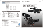
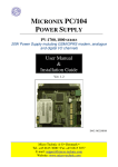
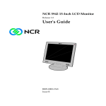
HITACHI Instruction Manual VL-21A 1 Table of Contents 1. Document History 2. Specifications 2.1 Lens 3. Measurement Specifications 4. Environment Condition and Test 4.1 High Temperature Storage Test 4.2 Low Temperature Storage Test 5. Interface 5.1 Pin Assignment 5.2 J204-10 Pin Connector 5.3 Line in Pulse (Ex, FV) 6. Lens Test Condition 6.1 Zoom 6.2 Focus 6.3 Auto Iris 7. Appearance 8. Appendix 1 8.1 OSD (On Screen Display) 8.2 Menus and Operations 8.2.1 Main Menu 8.2.2 Focus 8.2.3 Exposure 8.2.4 BLC 8.2.5 White Balance 8.2.6 3D-DNR 8.2.7 Special 8.2.8 General 8.3 Specifications 8.4 Communication Protocol 9. Appendix 2 9.1 Measurement Conditions 9.2 Measurement Procedure 9.2.1 Video Output Level 9.2.2 Color Reproduction 9.2.3 Luminance S/N 9.2.4 Horizontal Resolution 9.2.5 Low Luminance Sensitivity 10. Contact Information 2 3 3 3 5 5 5 5 5 5 5 5 6 6 6 6 7 8 8 10 10 10 11 12 12 13 13 15 16 17 19 19 20 20 21 21 22 22 23 1. Document History Revision Rev A Issue Date 07-21-11 Reason CN# Initial Release 11-00 2. Specifications Signal System Scanning System Scanning Frequency (H) Scanning Frequency (V) Image Sensor Total Pixels Effective Pixels 2.1 NTSC 2 : 1 Interlace 15.734KHz 59.94Hz 1/4” IT CCD 811 (H) x 508 (V) 768 (H) x 494 (V) 410K 380K Lens F1.6 (W) ~ 3.7 (T) (± 7%), f = 3.6 ~ 97.2mm ( ± 7%) x27 Zoom Video Auto Focus High Durability Zoom Lens Zoom Durability Focus Durability Iris Durability Focus Length Signal Process Sync System More than 500K at Room Temperature More than 1,000K at Room Temperature More than 500K at Room Temperature ∞ ~1.0m (Tele) ~ 0.01m (Wide) Digital Signal Processing Internal / External Camera Functions Optical Zoom Digital Zoom Video Focus TELE ~ WIDE (Zoom Speed: 4 sec) Off / On (x 10 times) Auto / Manual (NEAR ~FAR) / Push Auto Manual Mode Zoom Start Zoom Stop Manual Manual (AF Action is activated for a moment before focus stops) White Balance AUTO / Indoor / Outdoor / Push Auto / Manual (R&B Gain Level UP/DOWN) Special (R or B Gain Level Control) Shutter Speed AUTO / Manual (1/60 ~ 1/10000 (NTSC) Iris Control AUTO / Manual (Manual Iris Level: UP ~ Down Gain Control AUTO / Manual (Manual Iris Level: UP ~ Down 3 Sharpness Manual (Sharpness UP ~ Down) Brightness Manual (Brightness UP ~ Down) Negative Off / On OSD Function On / Off, English / Chinese (Appendix 1) Flickerless Off / On 1/100 sec Shutter Set NTSC Back Light Normal / Zone Selectable Day & Night Function Auto / Day / Night Video Output Levels Video Level = 0.714 ± 0.07v (100 ± 10 IRE) Sync Level = 0.286 ± 0.035v (40 ± 10 IRE) Burst Level = 0.286 ± 0.035v (40 ± 10 IRE) Color Reproduction Color Red Amplitude (%) 200 ± 40% Phase (°) 103 ± 20° Blue 130 ±40% 345 ± 20° Yellow 115 ± 40% 170 ± 20° Burst 100% Base 180 ± 20° Horizontal Resolution More than 580 TV Lines (High Resolution) Luminance S/N More than 50db Sensitivity Typ. 1 lux at signal level 30 IRE (Lens—F: F=1.6 (WIDE) AGC Gain: Max) Day Mode: 1.2 lux, Night Mode: 0.25 lux, Digital Slow Shutter: 0.00005 lux Supplied Voltage 11.5 v ~ 15.0 v DC (recommended 12.0 ± 0.5v) Camera will not turn on below 11.5 v DC Supplied Current 240 ma (steady state) Power Consumption 4.56 watts Dimensions 48.0mm (W) x 51.5mm (H) x 81.6mm (D) Weight 205g (approximate) Appearance / Dimensions Body Color See Section 7 Black 4 3. Measurement Specifications See “Appendix 2” for Standard Measurement Condition and Measurement Procedure 4. Environment Condition and Test Operating Condition Temperature -10°C ~ 60°C (Recommendation: -5°C ~ 50°C) Humidity 20% ~ 60% Storage Condition Temperature -40°C ~ 60°C Humidity 0% ~ 90% 4.1 High Temperature Storage Test In Storage condition at a temperature of 60°C for 72 hours, t hen leaving it at Normal Temperature for 8 hours, there will be no problem in performance. 4.2 Low Temperature Storage Test In Storage condition at a temperature of -40°C for 72 hours, then leaving it at Normal Temperature for 8 hours, there will be no problem in performance. 5. Interface 5.1 Pin Assignment TTL Communication (10 Pin FFC Connector; Maker LinkWork 1.0mm Pitch, Upper Contact) 5.2 J204 - 10 Pin Connector Pin Name I/O Level 1 2 3 4 5 6 7 8 9 10 Output Output Chroma Out Luminance Out Video Ground Composite Video Output 11.5 to 12.5 volts DC C Out Y Out Gnd V Out 12 V Key 1 Key 2 RXD TXD Gnd Output Input Input Input Output Input CMOS Level 5v (low: ≤ 0.8v, High: ≥ 3.7v CMOS Level 5v (low: ≤ 0.8v, High: ≥ 3.7v Power / Data Ground 5v 5.3 Line In Pulse (Ex, FV) 0v 200nsec min 60 Hz ±0.25Hz * The 10 pin Connector (JAE) over the camera module is used for manufacturing. (Not for user) 5 6. Lens Test Condition 6 7. Appearance 7 8. Appendix 1 8.1 OSD (On Screen Display) 1) OSD Display Position The OSD (On Screen Display) is as follows: 2) Description 8 9 8.2. Menus and Operations 8.2.1. MAIN MENU The main menu is shown below. 9 functions can be selected. Many of these sections have subsections as described in the proceeding pages. Each section has INITIAL and EXIT. INITIAL: Resets the function back to the factory default setting for that particular category EXIT: Closes the menu or submenu and moves you back to the main menu. MENU FOCUS EXPOSURE BLC WHITE BAL 3D-DNR SPECIAL GENERAL INITIAL EXIT 8.2.2. FOCUS Sets camera zoom and focus FOCUS FOCUS MODE FOCAL DIST ZOOM START ZOOM END ZOOM SPEED REFRESH MODE REFRESH TIME INITIAL EXIT MANUAL 50CM X001 X270 3 OFF NOT USED ON FOCUS MODE AUTO; Focuses automatically MANUAL*: Focuses manually via end user. *Note: Automatic focus in manual mode is only possible when the location of the zoom lens has changed or when the “temporary automatic focus” category is selected. Automatic focus is also possible based on external AF command. FOCAL DIST Minimal distance the camera can focus. EX: 10cm: Objects closer than 10 cm cannot be brought into focus. ZOOM START Minimum zoom movement. Possible from x 001 to x 270. 10 ZOOM END Maximum zoom movement. Possible from x001 to x270. ZOOM SPEED Zoom speed movement. Possible from x1 to x27 MENU FOCUS EXPOSURE BLC WHITE BAL 3D-DNR SPECIAL GENERAL INITIAL EXIT 8.2.3. EXPOSURE EXPOSURE AUTO NOT USED NOT USED NOT USED 25 OFF FLD 4 ON AE MODE SHUTTER IRIS AGC BRIGHTNESS FLICKERLESS D.S.S. INITIAL EXIT AE MODE AUTO, MANUAL BRIGHTNESS Can be adjusted from 0 (dark) to 48 (bright). Note: Not used while in manual mode. FLICKERLESS Removes screen flickering caused by discordance of frequency and lighting. D.S.S. Use under very low light conditions for full color surveillance. OFF< FLD 2 FLD 128 11 8.2.4. BLC Use to select BLC mode. MENU FOCUS EXPOSURE BLC WHITE BAL 3D-DNR SPECIAL GENERAL INITIAL EXIT NORMAL, R2, R1, D2, D1, U2, U1 8.2.5. WHITE BAL Adjusts picture color MENU FOCUS EXPOSURE BLC WHITE BAL ATW, PUSH, OUTDOOR, INDOOR MANUAL (Red, BLUE, EXIT) 3D-DNR SPECIAL GENERAL INITIAL EXIT ATW Auto Trace White Balance PUSH Can be used in Temporary Automatic Mode only. Color will automatically be adjusted (the word “pressed” will be displayed). RED Adjusts R-Gain value from 0 - 255 BLUE Adjust B-Gain value from 0 - 255 12 8.2.6. 3D-DNR 3D digital noise reduction used to reduce grainy image MENU FOCUS EXPOSURE BLC WHITE BAL 3D-DNR SPECIAL GENERAL INITIAL EXIT OFF, HIGH, MIDDLE LOW MENU FOCUS EXPOSURE BLC WHITE BAL 3D-DNR SPECIAL GENERAL INITIAL EXIT 8.2.7. SPECIAL Special settings to fine tune your camera. D-EFFECT SHARPNESS FREEZE COLOR MOTION PRIVACY INITIAL EXIT SPECIAL OFF 6 OFF ON 13 8.2.7.1. MOTION When there is movement of the subject on the screen there will be an alarm, or the user will be informed through communications on “MD” will display on the screen. NOTE: There is a signal every time there is movement by the subject. If motion is detected, MD (Motion Detector) is displayed on the upper left of the screen. Caution: An error can occur in the motion detection function in the following cases: When lighting is unsteady When light changes often even though there is no movement of the subject. Note: It is recommended that this function should be used after setting the detection sensitivity and the zone state after videoing the environment for an extended time. ZONE SELECT ZONE STATE SENSITIVITY INITIAL EXIT MOTION CENTER OFF 8 OFF ZONE SELECT Zone can be set to UPPER, RIGHT, CENTER, or WHOLE detection field as shown. UPPER LEFT CENTER RIGHT LOWER SENSITIVITY Sets sensitivity to detect movement from 1 (low) to 15 (high). MENU FOCUS EXPOSURE BLC WHITE BAL 3D-DNR SPECIAL GENERAL INITIAL EXIT 14 8.2.8. GENERAL General camera settings. GENERAL CAM ID ID DISPLAY CAM TITLE LANGUAGE PROTOCOL BAUDRATE VERSION INITIAL EXIT OFF OFF ENG DEF 9600 VER 1.1N OFF CAM ID Displays the camera’s ID from 0 - 255. LANGUAGE Displays the currently set language. PROTOCOL DEFAULT, P/D (Pelco D) P/P (Pelco P) 15 8.3. Specifications Signal System NTSC Scanning System 2 : 1 Interlace Horizontal Scan Frequency 15.734 KHz Vertical Scan Frequency 59.94 Hz Image Sensor 1/4 Inch Micro Lens IT CCD Total Pixels 811 (H) x 508 (V) 410K Effective Pixels 768 (H) x 494 (V) 380K Horizontal Resolution 580 TV Lines (BW 600 TV Lines), Sharpness Max. S/N Ratio More than 50db (AGC off) Lens 27x Zoom Video AF (f1.6 (W), f3.7 (T) f = 3.6 ~ 97.2mm) Angle of View (HOR) 55.21° ~ 2.12° Minimum Illumination Day Mode: 0.5 lux (30 IRE) / Night Mode: 0.1 lux (30 IRE) / DSS (128 FLD) Mode: 0.0005 lux (30 IRE) Synchronization Internal Signal Output 1 V p-p Composite Output with 75Ω Terminated Power Consumption 12 V DC, 0.5 amps / Max 6 watts Dimensions (W x H x D) 65 x 62 x 122 Weight Approx 325 grams 16 8.4. Communication Protocol 17 18 9. Appendix 2 9.1 Measurement Conditions Standard Measurement Conditions Supplied Voltage DC 12 volts ± 0.5 volts Ambient Temperature 23° C Humidity 60% RH Measurement Fixture Video Output, DC input, RS-232C level Convert (5Vp-p -> 12Vp-p) Power Supply 12 volts ± 0.5 volts Color Monitor CMM20 - 11, Shibasoku or Equivalent Monochrome Monitor More than 800 TV Lines of Resolution Waveform / Vector Scope 1720A, Tektronix or Equivalent S/N (Signal to Noise) Meter VN31AX, Shibasoku or Equivalent Illumination Meter / Color Temperature Meter XY - 1 / CL - 100, Minolta Camera or Equivalent Light Box Dai Nippon Printing Co. -Color Temperature 3200° K ± 100° K -Illumination More than 2000 lux Test Charts (Transparent Chart) Color Bar Chart, Dai Nippon Printing Co. Gray Scale Chart, Dai Nippon Printing Co. (Gamma 0.45) Resolution Chart, Dai Nippon Printing Co. (Reflective Chart) Gray Scale Chart, Murakami Color Research Lab Light Source Halogen Lamp (with Dimmer Switch) Color Temperature 3200° K ± 100° K Illumination Variable with Dimmer Color Temperature Filter LB 140, Hoya or Kenko or Equivalent (Color Temperature Conversion Filter) Adjustment PC With Serial Port 1 or 2 RS-232C Cable Each Terminal Connector (D-Sub 9 pin) 19 9.2. Measurement Procedure 9.2.1. Video Output Level TEST CONDITIONS Refer to “MEASUREMENT CONDITIONS” MEASURING SYSTEM System 1 PROCEDURE 1. Shoot the gray scale chart, and zoom WIDE or TELE to fit the chart to the monitor 2. Measure the video output level on the waveform monitor (Before the above measurement, Measure the SYNC and BURST levels) SPECIFICATION: Video Level A 100 ± 10 IRE Sync Level B 40 ± 5 IRE Burst Level C 40 ± 5 IRE 20 9.2.2. Color Reproduction TEST CONDITIONS Refer to “Measurement Conditions” MEASURING SYSTEM System 1 PROCEDURE: 1. Shoot the color bar chart and zoom WIDE or TELE to fit the chart to the monitor. 2. Measure the color amplitude and color phase on the vector scope of Red, Blue, and Yellow. (Before the above measurement, Adjust the burst amplitude and phase on the vectorscope so that the burst level becomes 100% and its phase becomes 180°. SPECIFICATION: COLOR RED BLUE YELLOW BURST Amplitude (%) 150 ±40% 100 ±40% 125 ±40% 100% 98 ± 20° 348 ± 20° 182 ± 20° 180° Phase ( ° ) 9.2.3. Luminance S/N TEST CONDITIONS Refer to “Measurement Conditions” MEASURING SYSTEM System 1 PROCEDURE: 1. Shoot the light box and zoom WIDE or TELE to fit the chart to the monitor. 2. The noise meter settings are: Input Level : Preset High Pass Filter ; 100KHz Low Pass Filter : 4.2MHz Sub-carrier Trap : On Weighting : On Sag & Hue Comp. : Optimum 3. Measure the maximum S/N on the noise meter. SPECIFICATION: More than 50 db (NTSC) 21 9.2.4. Horizontal Resolution TEST CONDITIONS Refer to “Measurement Conditions” MEASURING SYSTEM System 1 PROCEDURE: 1. Shoot the resolution chart and zoom WIDE or TELE to fit the chart to the monitor. 2. Adjust the brightness and contrast of the B/W monitor so that each step of the gray scale portion of the chart can be observed. 3. Change the scan size of the monitor to under scan. 4. The reference arrows on the resolution chart are positioned at the edge of the under scanned picture. 5. Change the scan size of the monitor from under scan to over scan. 6. Measure the maximum horizontal resolution on the picture. SPECIFICATION: More than 480 TV Lines (High Resolution) 9.2.5. Low Luminance Sensitivity TEST CONDITIONS Refer to “Measurement Conditions” MEASURING SYSTEM System 1 PROCEDURE: 1. Shoot the gray scale chart and zoom WIDE or TELE to fit the chart to the monitor. 2. Adjust the brightness of the light source by using the dimmer switch so that the white peak level of the chart becomes 30 IRE on the waveform monitor. 2. Measure the level of illumination by using the illumination meter. SPECIFICATION: 22 10. Contact Information For technical assistance with this product, please contact the supplier from whom the product was purchased. Distributed by: Hitachi Kokusai Electric America Ltd. Industrial Video Systems 150 Crossways Park Drive Woodbury, NY 11797 Phone East : 817‐490‐5124 West: 858‐565‐7501 Fax: 817‐490‐6116 www.hitachikokusai.com/IVS 23