1
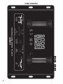
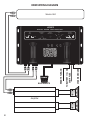
DIGITAL BASS RESTORATION
HDBR
HDBR
DIGITAL BASS RESTORATION
Congratulations on purchasing the HDBR! You are now the proud owner of the finest
and most accurate bass enhancing and restoration system available.
INDEX
PAGE
Specifications and Feature Descriptions...........................................................................................................1
HDBR Drawing and Functions.........................................................................................................................2-3
Application/ Diagram...........................................................................................................................................4
Troubleshooting...................................................................................................................................................5
Product Warranty.................................................................................................................................................6
For instructional videos on wiring
the HDBR, please
visit our YouTube channel at
www.youtube.com/maxxsonicsusainc
The contents of this manual may not be reproduced or copied without the written consent of MAXXSONICS USA, Inc.
HDBR SPECIFICATIONS
Maximum Input Level.............................................................................................15V rms
Maximum Output Level......................................................................................13.5V peak
Frequency Response......................................................................10Hz - 100KHz; +/-1dB
Total Harmonic Distortion.........................................................................................0.003%
Signal to Noise Ratio.................................................................................................130dB
Balanced Input Noise Rejection.................................................................................>60dB
Input Impedance.....................................................................................................10 Kohm
Output Impedance................................................................................................150 Ohms
Power Supply......................................................................................High headroom PWM
Power Draw...............................................................................................................150mA
Recommend fuse rating..............................................................................................1 Amp
HDBR FEATURES
Bass Driver: The HDBR contains a Bass Driver circuit that accurately recreates and injects
Low Frequency information back into the signal path. What that means in everyday terms is
that the HDBR will give more bass impact to your best compact discs or lowest quality
recordings.
Bass Equalization Circuit: The HDBR has a unique equalization circuit that contours the
restored bass to your speaker systems.
Dash Mount Remote Control: The HDBR comes with a Dash Mountable Remote Control
that allows you to enjoy the effects of the HDBR without having to leave the drivers seat. The
Dash mount Control has an LED indicator that will grow brighter as you add more bass or
dimmer when you decrease it.
Bass Maxximizer Indicator: Not only does the HDBR provide good music to your ears, but
it also gives you some visual enjoyment as well. On the chassis of the HDBR there are three
LED indicators that flash when the bass maxximization circuit is activated.
Bass Output Control: The HDBR has the ability to produce large amounts of deep, ear
blowing bass without damaging your speakers. The Bass Output Control circuit allow the
HDBR to maxximize the bass output of any autosound audio system while restraining
destructive bursts.
1
2
BALANCED
UNBALANCED
RCA
INPUT
WIDE
CENTER
FREQUENCY
7V
THE
FROM
GODS
9V
.2V
2.5V
OUTPUT LEVEL
4.5V
POWER
NARROW
FREQUENCY
RANGE
HDBR
DIGITAL BASS RESTORATION
200-Ohms
ISOLATED
GROUND
GROUND
ISOLATION
HDBR DRAWING
CENTER FREQUENCY: This knob allows you to select the frequency you want the HDBR
bass restoration circuit to maxximize.
FREQUENCY RANGE: This knob allows for you to adjust the range of frequencies from your
center point. All the way to the left will include the maxximum frequencies to maxximize, while
all the way to the right will enhance only a limited amount f frequencies near your CENTER
FREQUENCY.
OUTPUT LEVEL CONTROL: This knob allows for you to control the amount of signal voltage
you are sending through the RCA OUTPUTS to your amplifier(s). It is important to note that the
MBC1 has a built in line driver capable of sending an ‘ultra clean’ 9 volts of signal output to
your amplifier(s). Be sure to reference the end panel silk screening for GAIN/LEVEL
CONTROL on your amplifier(s). Some amplifiers cannot handle the full 9 volts and going
beyond the specified Input range on your amplifier(s) can be damaging.
GROUND ISOLATION: Occasionally alternator whine may appear in the system because the
source unit and amplifier may use different grounds. To help in this situation, we have provided
alternative grounding options. MAKE SURE THE SYSTEM IS OFF BEFORE SWITCHING
THIS SELECTION!
RCA INPUT: In most cases you will leave the selection switch in the BALANCED position. In
some systems the source unit may look for a ground through the RCA connections. In this
event you would switch the selection to UNBALANCED.
INPUT: RCA’s from source unit connect to this location.
OUTPUT: RCA’s from the HDBR connect to the inputs of your amplifier(s).
REMOTE: The BPR-1 Bass Processor Remote dash mount control connects here. This
remote allows for complete control of your audible subwoofer level along with a LED indicator
which brightens as you increase bass enhancement.
REM / 12V / GND:
-REM: Connects to a 12V+ switched source. The REM cable should have 12V when the
source unit is on and 0V when the source unit is off. Typically this would connect to
the ‘Power Antenna’ output wire on the back of your source units’ wiring harness.
-12V: Connects to a 12V constant source. The Positive battery terminal is recommended and a
1 amp in-line fuse is required.
-GND: Connects to a ground location. Be sure that all paint is removed from the area of this
connection on the vehicle chassis.
3
HDBR WIRING DIAGRAM
Source Unit
HDBR
DIGITAL BASS RESTORATION
RCA
INPUT
FREQUENCY
RANGE
CENTER
FREQUENCY
OUTPUT LEVEL
4.5V
BALANCED
GROUND
ISOLATION
2.5V
7V
UNBALANCED
GROUND
WIDE
9V
NARROW
.2V
200-Ohms
ISOLATED
POWER
FROM
GODS
MAX
Amplifier
4
CHASSIS GROUND
MIN
BASS REMOTE
TO BATTERY +12v VIA
5 AMP FUSE
HDBR
REMOTE TURN-ON
THE
TROUBLESHOOTING A SYSTEM
The key to finding the problem in a troubled sound system is to isolate parts of that system in a logical fashion to track down the
fault.
The diagnostic system will not shut down the HDBR or the amplifier(s), although the amplifier(s) own protection circuitry may shut
the amplifier(s) down should a fault status occur. At which time you will need to consult the owners manual for that particular
amplifier.
Low output power
1 - Check that level controls have been set up properly.
2 - Make sure that the battery voltage, as measured at the amplifier(s) and HDBR +12 volt and ground terminals, is 11 volts or
more.
3 - Check all +12 volt and ground connections.
Fuses blowing
1 - Insure that the voltage to the unit does not exceed 15 volts.
2 - A short on the main +12 volt cable from the battery to the vehicle chassis will cause the main fuse to blow.
3 - If the MBC1 is blowing fuses continually with only +12 volt, ground and remote leads connected, the unit may be faulty.
System does not turn on
1 - Check all fuses.
2 - Check all connections.
3 - Measure the +12 volt and remote turn on voltages at the amplifier(s) and HDBR terminals. If these are non existent or low, take
voltage measurements at fuse holders, distribution blocks, the head unit’s +12 volt and remote leads to localize the problem.
Noise problems
System noise can be divided into two categories, hiss, and electrical interference.
Hiss, or white noise
1 - High levels of white noise usually occur when level controls are turned up too high - reduce the levels until the noise is no
longer present.
2 - Another major problem that can cause excessive hiss, is a noisy head unit - unplug the HDBR Input RCA’s, and if the hiss level
reduces, the source unit is at fault.
Electrical interference
The inside of an automobile is a very hostile electrical environment. The multitude of electrical systems, such as the ignition
system, alternator, fuel pumps, air conditioners, to mention just a few, create radiated electrical fields, as well as noise on the +12
volt supply and ground. To try and eliminate this noise, run a wire from the radio ground wire to the ground input on the HDBR.
A ticking or whine that changes with engine RPM:
1 - This problem could be caused by radiation pickup of RCA cables that are too close to a fuel pump or a distributor.
2 - Check that the head unit ground is connected straight to the vehicle chassis, and does not use factory wiring for ground.
3 - Try to supply the head unit with a clean +12 volt supply directly from the battery +, instead of using a supply from the in dash
wiring/fusebox.
A constant whine:
This type of noise can be more difficult to pinpoint, but is usually caused by some kind of instability, causing oscillations in the
system.
1 - Check all connections, especially for good grounds.
2 - Make sure that no speaker leads are shorting to exposed metal on the vehicle chassis.
3 - RCA cables are notorious for their problematic nature, so check that these are good, in particular the shield connections.
5
Maxxsonics Limited Warranty
As the manufacturer of Maxxsonics, MB Quart, Hifonics, Crunch and Autotek car audio
products, Maxxsonics USA Inc. Warrants to the original consumer purchaser the amplifier
to be free from defects in material and workmanship for one (1) Year from date of purchase.
All other parts and accessories of the system are warrantied to be free from defects in
material and workmanship for one (1) year from date of purchase. Maxxsonics will repair
or replace at it’s option and free of charge during the warranty period, any system
component that proves defective in materials and workmanship under normal installation,
use and service provided that the product is returned to the authorized Maxxsonics dealer
from where it was purchased. A photo copy of the original receipt must accompany the
product being returned.
Valid purchase receipts will contain the name and address of the authorized reseller.
Any damage to the product as a result of misuse, abuse, accident, incorrect wiring,
improper installation, alteration of date code or bar code labels, revolution, natural
disaster, or any sneaky stuff because someone messed up, repair or alteration out side of
our factory or authorized service centers and any thing else you have done that you should
not have done is not covered.
This warranty is limited to defective parts and specifically excludes any incidental or
consequential damages connected therewith. This warranty is not to be construed as an
insurance policy.
Warranty on installation labor, removal, re-installation and freight charges are not the
responsibility of Maxxsonics USA Inc.
Warranty products damaged as a result of insufficient or improper packing materials are
not covered by this limited warranty and such damaged product will be returned “as is”
at the expense of the owner.
6
PART # F1211