1
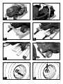
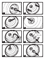
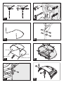
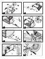
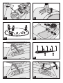
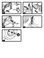
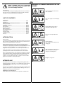
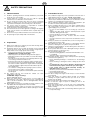
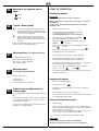
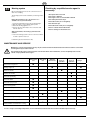
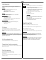
RS 17/102H HERITAGE TRACTOR Code149D INSTRUCTION BOOK (English Version) Code From serial No. 149D 260000001 Issue 01/11/05 MANUAL PART NO: 111-0442 (A) 1 2 3 4 5 6 7 8 2 9 10 11 12 Ø19 x Ø26 Ø20 x Ø42 13 14 15 16 3 ø7 2 1 17 18 19 20 Ø 6 (2x) M6 (2x) M6 x 45 (2x) 21 2 Ø 6 x Ø 12 (4x) 22 1 2 23 24 4 1 3 1 Ø6 x Ø18 2 Ø6 x Ø12 25 26 27 28 1 2 29 3 4 30 1 2 31 32 5 3 33 34 1 1 3 2 O I 2 II 35 36 ¾ 37 ½ ¼ 0 38 1 0 I 40 39 6 2 ON 1 2 11 OFF 2 41 42 2 1 43 1 44 45 7 3 GB Before assembly and start of operation, please read the operating instructions at all costs and comply with them. MEANING OF SYMBOLS INDICATED ON THE MOWER Dear Customer, You have bought a totally tested quality product. However, should you have any reason for complaints, please get in touch with your dealer, stating the code and serial number (see nameplate). Read operating instructions before start of operation. LIST OF CONTENTS Keep other people out of the danger zone. Manufacturer Introduction............................................................................... GB 8 Intended use............................................................................. GB 8 Meaning of symbols indicated on the mower.......................... GB 8 Safety precautions.................................................................. GB 9 Unpacking Lawntractor………………………………………….. GB 10 Assembly................................................................................ GB 11 First operation.......................................................................... GB 13 Operating elements.................................................................. GB 13 Start of operation..................................................................... GB 14 Care and maintenance............................................................ GB 16 Starter battery......................................................................... GB 18 Storage in winter...................................................................... GB 19 Trouble Shooting.................................................................... GB 20 Warranty................................................................……...……. GB 21 Pull the ignition plug out before maintenance and repair work. Do not use on slopes above 10° (18%). INTRODUCTION Dear customer, You have purchased a new machine. We want to thank you for the trust that you put into our quality products and hope that you will have much pleasure from working with your new machine. Attention, danger! Keep hands and feet away from the cutting gear. Before putting the machine into operation for the first time, please familiarise yourself with the contents of these operating instructions. If the machine is operated by people without sufficient qualifications or not according to the intended purpose, use of the machine may be dangerous. Please pay attention to the accident prevention directives. While mowing, keep other people, in particular children and animals, away from the working area. Please pay attention to the safety instructions contained in these operating instructions and to the safety instructions on the machine. Due to ongoing improvements of the product, the information contained in this manual is subject to alterations without the manufacturer being obliged to notify or to update, under the proviso that the essential properties for safety and operation do not change. In cases of doubt, please do not hesitate to contact your dealer. Danger: do not go here. INTENDED USE This lawnmower is only intended for mowing in private gardens with a maximum inclination of 10° (18%) - not for public parks, sports grounds or in farming or forestry. Other kinds of use are only permitted with original spare parts. Any other use is regarded as being misuse and results in forfeiture of the guarantee and rejection of any responsibility for damage to the user of third parties on the part of the manufacturer. Working hours for lawn tractors: Please observe the local directives for the operation of lawnmowers. GB 8 GB SAFETY PRECAUTIONS 1. General remarks 3. Instructions for use 1.1 3.1 1.7 1.8 Read the operating instructions carefully. Familiarise yourself with the proper use of the machine. People under 16 or people who have not read the operating instructions are not allowed to use the machine. Do not operate the machine when there are others, in particular children or animals, in the area. The person using the machine is responsible for third parties in the working area of the machine. The person using the machine is responsible for accidents involving other people or their property. Please keep these operating instructions for later use. The lawn tractor does not have approval according to the Highway Code. You are therefore not allowed to drive on public ways and roads with it. Never mow on slopes with an inclination of more than 10° (18%). No passengers may be transported on the machine. 2. Preparations The combustion engine may not be operated in enclosed rooms in which dangerous fumes can collect - danger of poisoning! Only mow your lawn in daylight or in good illumination. Please observe any local directives about when you are allowed to use the machine (see operating times for lawn tractors). Before starting the machine, switch off the mowing appliance, put the drive into neutral and operate the parking brake. Please remember that there are no "safe slopes". Mowing slopes with a lawn requires special attention. In order to protect yourself against tipping over, you should: – not stop or start suddenly if you are moving up or down the slope, – suppress the clutch slowly, leave the clutch depressed, in parti cular when driving down the slope, – keep the speed low on slopes and in tight bends, – pay special attention to hills, recesses and other invisible dangers, – never mow transverse to the slope if it has an inclination of more than 10°. Always pay attention to road traffic when you are crossing roads or working in the vicinity of roads. When driving the tractor, pay attention to low-hanging obstacles (branches, washing lines etc.) which can injure the driver. Switch the mowing appliance off when driving off the lawn, lift it to the highest cutting position. Never operate lawn tractors with a damaged housing or defective protective devices (e.g. grass box etc.). Before leaving the driver's seat: – switch the mowing appliance off and wait until the blades come to a standstill, – switch the engine off and remove the ignition key. Disengage the drive, turn the engine off and pull out the spark plug connector or the ignition key – before eliminating blockages or obstructions in the discharge channel – before checking or cleaning the mower or doing any other work on it – if a foreign body is hit. Look for damage to the machine and have the necessary repairs done before you start it again; – if the mower starts to vibrate unusually severely, an immediate check is necessary. – whenever you leave the mower unattended or transport it – before filling up with petrol – before removing the grass box. The basic setting of the engine in the factory is correct and must not be altered. Start and operate the starting switch carefully (see Chapter "Starting the engine"). Make sure that your feet are at a safe distance from the blade. Do not tip the mower when starting or turning the engine on. Do not start the engine if anyone is standing in front of the discharge channel. Keep your hands and feet out of the area of the rotating blade. Keep other people away from the discharge channel when the blade is rotating. Never use a lawn tractor with a rear discharge without a grass box or a vapour discharge. 1.2 1.3 1.4 1.5 1.6 3.2 3.3 3.4 3.5 2.1 Always wear sturdy shoes and long trousers while mowing. Never go barefoot or wear open sandals. 2.2 Completely check the area on which the machine is to be used and remove any stones, sticks, wires, bones and other foreign objects. Always watch out for foreign objects when mowing. 2.3 – Petrol is to be poured in before starting the engine. WARNING! Petrol is highly flammable! – Only keep petrol in the containers designed for this purpose. – Only fill the machine in the open and do not smoke when filling the machine. – The tank may not be opened or petrol topped up while the engi ne is running or when the machine is hot. – If petrol has been spilt, do not start the engine. Instead, remove the mower from the area contaminated with petrol. The spilt pe trol must be sucked or wiped off the engine and the housing with a cloth. No attempts at ignition may be made until the vapours have disappeared. – Use a funnel or a filling tube when pouring in petrol so that no fuel can leak onto the engine or onto the lawn. – For safety reasons, replace the tank lid and the petrol tank if they are damaged. 2.4 The exhaust and the area around the exhaust can reach temperatures of up to 80°. ATTENTION: danger of burning! Replace damaged silencers. 2.5 Before use, always make a visual check to see if the blade, the fastening bolts or the entire cutting unit are worn or damaged. In order to avoid an imbalance, worn or damaged blades must be replaced with new ones. 2.6 Ensure that the movement of one blade can lead to rotations of the other blades when mowing with more than one blade. 2.7 An examination by an expert is necessary if the machine stops immediately, e.g. after impact with an obstacle (damage to the drive shaft, bent blades etc.). 3.6 3.7 3.8 3.9 3.10 3.11 3.12 3.13 3.14 3.15 3.16 GB 9 GB 4. Instructions for maintenance and storage 4.1 Make sure that the nuts, bolts and screws are tight. 4.2 Be careful when adjusting - danger of injuries. Do not trap your fingers between the housing and the blade. Wear protective gloves. 4.3 Never store the lawn tractor with fuel in the tank inside a building in which petrol fumes can possibly come into contact with naked flames or with sparks - danger of explosion! 4.4 Only empty the petrol tank in the open. 4.5 Allow the engine to cool down before you put the machine into an enclosed area. 4.6 Avoid the risk of a fire by keeping the engine and the exhaust free of grass, leaves and grease (oil). 4.7 Check regularly to make sure that the grass box is in a satisfactory condition. 4.8 For safety's sake, worn or damaged parts must be replaced immediately. 4.9 Replacement blades and additional appliances may only be mounted on the lawn tractors intended for this purpose according to the manufacturer's instructions. This is the only way to maintain the safety and the performance of your lawn tractor. 4.10 Please ensure that the maintenance, checking and sharpening of the blade is only done by an authorised dealer. 4.11 Only use original replacement blades. Unpacking Lawntractor The lawntractor will be delivered on a solid wood pallet. To remove the packing, place the pallet on a level surface. Please follow the sequence for unpacking and for the respective wheel locks. 10 The numbers to the left of the text, e.g. , refer to the illustrations in the picture section of these operating instructions. Open cardboard packing at top. Remove staples and take off cardboard packing upward. 1 2 3 4 5 We would point out that we are not liable according to the Product Liability Act for damage caused by our machine as a result of a) b) improper repairs not carried out by our authorised service dealer, or if ORIGINAL SPARE PARTS are not used as replacement parts. Remove enclosed parts and packing materials. Remove wooden hoop. Remove front laths. Remove wooden blocks. Remove all nails on the pallet. Move mowing unit into highest position. See operating instructions under: >> Start-up - Adjusting cutting height << Lift tractor at rear and push off pallet. Dispose of pallet and packing materials properly. Secure the tractor from rolling away with the wheel locks! Now you can begin mounting equipment. GB 10 GB ASSEMBLY 13 Remove O-ring - do not re-use The following assembly work must be carried out before the first operation: 14 Fit one washer 1x 19 mm dia. x 26 mm dia. and 1x 20 mm dia. x 42 mm dia. each on axle - first 19 mm dia. x 26 mm dia.! 15 16 Insert lock washer in shaft groove and press down. 1. 2. 3. 4. 5. Installation of the wheels. Installation of the steering wheel. Installation of the driver's seat. Assembly of the grass box Fitting the grass box to the lawn tractor. Attention! Putting into operation (even test operation) before complete assembly has taken place is strictly forbidden - dangers of accidents! Fit cover cap. Assembly of the steering wheel 17 The information on directions (right, left, top etc.) for this appliance are to be understood in the direction of travel looking from the driver's seat. Point the front wheels straight ahead in the direction of movement. Push the 8 x 60 ∅ clamping sleeve about 10 mm into the bore of the steering wheel hub. The order of assembly steps is to be complied with, as otherwise flawless function cannot be guaranteed. Put the steering wheel onto the steering column. Ensure the correct position: the spoke is to point towards the driver's seat. Put the round iron (7 x 150 mm ∅) of the enclosed spark plug connector into the free bore of the steering wheel hub. Turn the steering wheel until the round iron can be pushed through the bore of the steering wheel. Please note: The figures stated to the left of the text, such as the 10 here, refer to the illustrations in the illustrated part at the front. Connect with steering wheel with the steering column by pushing in the 8 x 60 ∅ clamping bolt. Front wheels: Installing the driver's seat Lock both front wheels. 6 7 8 9 18 Lift tractor slightly by bumper and pull to front wheel. n Hexagonal recess hole screw Push washer toward wheel rim. Insert lock washer into shaft groove before washer and press down. 2x lock washer dia. 15x29x1.5 - contained in screw/bolt bag. 12 (2 x) (2 x) (2 x) (2 x) o Hexagonal recess hole screw / Wing screw M8 x 20 Fan-disk Ø 8.4 x Ø 15 (2 x) (2 x) Push the seat into the required position and tighten the screws by means of the enclosed socket wrench – 6 mm (Allen key)! Fit cover cap. The seat can be moved in a longitudinal direction by loosening the screw o. Lock both rear wheels. 11 M8 x 20 Fan-disk Ø 8.4 x Ø 15 Disk Ø 8.4 x Ø 24 Spacer bushing Ø 8.2 x Ø 14 Rear wheels: 10 Unscrew the driver's seal according to the diagram on the hinged console. Move tractor to rear wheel until rear wheel is heard to strike steering knuckle. Wheel axle protrudes from rim. O-ring Ø11 x 2.6 is fitted in the works – (secures the parallel key). GB 11 GB Assembling the grass box 19 Place the lower part of the frame on a suitable base (e.g. a table). 20 Screw the upper part of the frame onto the lower part of the frame on both sides. M 6 x 35 hexagonal head screw Ø 6 x Ø 18 shim Ø 6 x Ø 12 shim M 6 self-locking nut 26 27 28 (4 x) (4 x) (4 x) (4 x) Screw the box handle onto the box lid M 6 x 20 screw Ø 6 x Ø 12 shim Ø 6 x Ø 18 shim M 6 self-locking nut (2 x) (2 x) (2 x) (2 x) Position the box lid and screw onto the box frame M 6 x 40 hexagonal head screw (5 x) Ø 6 x Ø 18 shim (5 x) Ø 6 x Ø 12 shim (5 x) M 6 self-locking nut (5 x) Holder (2 x) Attention! Attention! Fit the Ø 6 x 18 shim under the screw head. Only tighten the nuts by hand to start with due to the subsequent fixing of the box fabric. Push the box strut (Ø 8 mm) through the base of the box and the lower part of the frame. Fit shim Ø 6 x Ø 18 under the screw head! Attention! The box strut must protrude by the same distance on both sides of the box. 21 Screw the transverse tube o onto the box frame. M 6 x 45 hexagonal head screw (2 x) Ø 6 x Ø 12 shim (4 x) Ø 6 curved shim (2 x) M 6 self-locking nut (2 x) 29 Attention: n Ø 12 x 13 spacer bushing o Gas-pressure spring p Ø 8 x Ø 15 shim q M 8 self-locking cap nut The ribs of the box base pointing upwards. Attention! Clip the fabric sack onto the box frame. Only tighten the cap nuts to such an extent that the gaspressure springs can still be pivoted Place the frame onto the box base of the fabric sack. 22 23 Thread the gas spring onto the box strut in the order shown and screw tight. Carry out this procedure on both sides. Remove the upper frame screw connection and screw the fitting flap of the fabric sack together with the upper and lower part of the box frame. (2 x) (2 x) (2 x) (2 x) Assembling the grass box on the tractor 30 Fit the Ø 6 x Ø 18 shim under the screw head. Carry out this procedure on both sides. Hold the grass box by the box handle in one hand. With the other hand - gently pressing onto the box lid - position the upper part of the frame onto the box holding arms and push forwards until the grass box engages in the bearings. Attention! 24 The arrows on the box lid and the seat console must match. Clip the stopper n into the opening on the right-hand side of the box lid. Screw the contact elbow o for the box switch onto the box lid. Ø 6 x 25 counter-sunk screw 31 (2 x) If the gap between the box lid and the seat console is too large, the box holding arms can be adjusted by loosening the screws in the directions shown Attention! Make sure that the position of the contact elbow is as shown. 32 25 Push the forkhead n of the gas-pressure spring across the fitting lug o of the back wall until the bores are flush. Push the securing bolts p through the forkhead and the lug and lock them. Screw the box handle n onto "superstructure left" o and "superstructure right" p. M 8 x 60 screw (2 x) Ø 8 x Ø 15 shim (2 x) shim (2 x) Attention! Carry out this procedure on both sides. The connection contours of the two superstructures must correspond with the outer contour of the box lid. GB 12 GB FIRST OPERATION Starter battery As a matter of principle, the starter battery is charged ex works. Should starting problems nevertheless occur, the battery must be charged before the first operation of the lawn tractor. The lawn tractor may only be put into operation when the assembly has been completed. During the operation, the starter battery is charged by the engine. Under normal conditions, re-charging will only be necessary after longer periods without use (longer than 3 months). Safety systems Charging the starter battery: see "Maintenance and Service". The lawn tractor is fitted with 3 safety contacts which are operated by a) the driver's seat b) the grass box and c) the pedal. We recommend charging this maintenance-free and gas-tight battery with a charging device specifically suited for this (can be purchased from specialist dealers). If a different charging device is used, the charging current may not exceed 5 A and the charging voltage 14.4 V. If there is a higher charging voltage, there is a danger of the starter battery exploding. The engine can only be started if The starter battery is recyclable. the driver is sitting on the driver's seat, the brake has been operated and the mowing appliance has been switched off. Used and defective starter batteries must not be disposed of via domestic refuse. Your dealer, the manufacturer of the device or the local battery collection points (pay attention to the local directives) will assure proper disposal of these batteries. The engine is automatically switched off if a) the driver gets off without operating the brake b) the driver gets off with the mowing appliance still running c) the grass box is opened or removed with the mowing appliance still running. 33 OPERATING ELEMENTS 35 Filling with engine oil and fuel. n Gas lever The engine speed is regulated with the gas lever. In order to mow as effectively as possible, the gas lever should be switched to . Opening the bonnet: 34 1. Put your hands into the ventilation slots of the bonnet. 2. Gently pull the bonnet in the direction of the steering wheel and lift it up until it makes contact with the bumper. o Light switch Use the light switch to switch the headlights on. Pour engine oil in before the first operation – see operating instructions of the engine manufacturer. Regularly check the oil level. p Ignition lock Fuel: standard petrol - lead-free. To start the engine, put the ignition key into the ignition lock and turn to the right to position "II". TAKE CARE WHEN POURING FUEL IN As soon as the engine is running, let go of the ignition key (ignition key returns to position "I"). Only fill the petrol tank in the open. Do not smoke. Do not pour in petrol when the engine is running or hot. Use a suitable funnel attachment or feeder funnel to pour in petrol so that no fuel can be spilt on to engine, the housing or on the lawn. If petrol is spilt, do not start the engine. Remove the mower from the area contaminated with petrol. The spilt petrol must be sucked or wiped off the engine and the housing with a cloth. No attempts at ignition may be made until the vapours have disappeared. To switch the engine off, put the gas lever onto turn the ignition key onto position "0". 40 Mowing appliance switch The mowing appliance is operated with this toggle switch. Switch position I Switch position 0 Tyre pressure Check the tyre pressure at regular intervals. Examine the precise air pressure on the tyre. 1 PSI = 0.07 bar The tyre pressure can be checked without any difficulties by using a standard foot-pump. GB 13 , then - mowing appliance switched on - mowing appliance switched off GB 36 Meaning of the symbols on the pedal Clutch Brake 36 START OF OPERATION Starting the engine IMPORTANT! Check the oil level before each start of operation. "Clutch / Brake" pedal Engine exhaust fumes contain carbon monoxide, a non-odorous and lethal gas! For this reason, never start the engine in enclosed or badly ventilated rooms. n • Sit down on the driver's seat. • Push the right-hand pedal (clutch/brake) right down - possibly engage with the stop lever. The mowing appliance must not be switched on. • • For a cold start, put the throttle lever onto CHOKE Starting the engine with a "HONDA engine" During the starting procedure, hold the throttle lever in the o If the pedal is half pushed down, the clutch is disengaged. If the pedal is completely pushed down, the clutch is disengaged and the disk brake of the transmission operated. With the pedal completely pressed down, the pedal can be locked in the "Brake" function by pushing the stop lever to the left (with the heel of the shoe). Pushing the pedal down again cancels the locking - the stop lever returns to the original position. 37 Switching lever (for hydrostat drive) Possible transmission positions: Forward gear - infinitely adjustable Reverse gear - infinitely adjustable. and a neutral position. 39 Switching lever (for 5-gear transmission) . CHOKE position. If you let go of the throttle lever, it automatically returns to the FAST position. • If the engine is warm, put the throttle lever onto FAST . • Put the ignition key into the ignition lock. • Turn the ignition key to the right to position "II" (Start). • When the engine is running, let go of the ignition key. (The ignition key automatically returns to position "I"). • An attempt at starting should only last for about 5 seconds so that the starter battery is not strained unnecessarily. • As soon as the engine is running, put the throttle lever into a position between and . • The engine should warm up for a few minutes before the mowing appliance is switched on. With the switching lever, 5 forward gears 1 reverse gear and 1 neutral position can be switched. 40 Position lever for adjustment of cutting height Stopping the engine • Switch off the mowing appliance. • Put the gas lever onto • Briefly press the brake pedal down - if necessary, engage the brake pedal. . • Turn the ignition key to the left to position "0". The mowing appliance is lifted or lowered with the position lever. • If the lawn tractor is left unused or unattended, remove the ignition key and engage the brake pedal. Six positions are available. In order to get from a higher to a lower position, the push button on the end of the lever must be pushed to unlock it. Driving with the lawn tractor In order to reach a higher position, simply push the lever upwards into the required position • Start the engine. • When the engine is running, select the corresponding forward or reverse gear. With a hydrostat drive, pre-select the corresponding position in forward or reverse drive. For the first use of the lawn tractor, we would advise that you only choose 1st gear or set the hydrostat drive to MIN. • To start motion, slowly release the clutch/brake pedal. IMPORTANT! Do not switch the 5-gear transmission while driving. The lawn tractor must be stationary in order to change gear. GB 14 GB Brakes • Driving without traction (pushing) Press the right-hand pedal down completely in order to brake. IMPORTANT! Only with the engine switched off and the blades stationary! a) For a 5-gear transmission: 1. Put the switch lever into position 0. 2. Release the brake. Switching the mowing appliance on • Only switch the mowing appliance on with the engine running. • Put the gas lever into the • Set the required cutting height. • Put the mowing appliance switch onto position "I". 41 position. b) For a hydrostat drive: 1. Remove or lift up the grass box. 2. Pull out bypass lever n and engage downwards o. 3. Release the brake. The lawn tractor can now be pushed without any difficulty. IMPORTANT! When you switch the mowing appliance on, the mower should not be standing in long grass. Set to the highest cutting height. Switching the mowing appliance off Driving and mowing In order to achieve a tidy mowing result, the traction speed must be adapted to the state of the lawn. 38 a) Lever position for hydrostat drive: – long / thick grass and wet grass: 0 - ¼ • Put the mowing appliance switch onto position "0". • The mowing appliance can be switched off both at a standstill and also during movement. – normal grass, weekly cutting: ½ - 2/3 The lever positions from 2/3 - 1/1 are reserved for driving without mowing. IMPORTANT! b) Lever position for 5-gear transmission: A rotating / slowing blade can cut hands and feet. Therefore, keep your hands and feet away from the blades. 39 – long / thick grass and wet grass: 1st gear – normal grass, weekly cutting: 2nd - 3rd gear 4th and 5th gear are reserved for driving without mowing. Setting the cutting height 40 The blades are raised and lowered with the position lever to the right of the driver's seat. Six height settings with a cutting height between 30 and 90 mm are possible. Allow the position lever to engage at the height adjustment position required. Adjustment of the cutting height can be done both at a standstill and also during movement. IMPORTANT: Set the highest cutting height: In a normal case, the cutting height is about 4-5 cm. This corresponds to the 2nd/3rd position of the height adjustment. Cut moist or wet grass with a higher cutting height. The best thing to do with very long grass is to cut it twice. For the first cut, set the machine to max. cutting height and set it to the required height for the second cut. Driving on slopes Special care is needed when driving on slopes. Please observe the following information: - before switching the cutting appliance on - when driving without mowing GB 15 – Do not drive on slopes with an inclination of more than 10° (18%). – Do not jolt when starting. – Keep the speed low. – Do not stop or accelerate strongly. – Do not declutch when going down the slope. GB Emptying the grass box Grass box Take the grass box off the lawn tractor. The grass box can be emptied from the driver's seat. 28 IMPORTANT! The gas springs must be removed before you can take the grass box off the lawn tractor. Clean the fabric sack from the outside with a jet of water. If necessary, also clean the inside of the fabric sack with a brush. When the grass box is full, an acoustic signal can be heard. The box should be emptied now at the latest. Switch the mowing appliance off - acoustic signal goes off. Housing / engine / transmission 42 The engine and all the bearings (wheels, transmission, blade bearings etc.) must not be cleaned with water, in particular not with a highpressure cleaner. Empty the grass box: n o p Press the box locking button. Any water penetrating into the ignition unit, into the carburettor and the air filter can cause damage. Water in the bearings can lead to a loss of lubrication and thus to the destruction of the bearings. Push the box locking button backwards until it engages. To remove dirt and residue of grass, use a cloth, a hand-held sweeper, a long-handled brush etc. Pull the grass box upwards by hand. Shake the grass box a number of times in order to empty it completely. Electrical unit Do not clean the electrical unit with water. Penetration of water into the electrical unit (switch, display, cable, operating elements etc.) can lead to damage. If the grass box is lifted or removed with the mowing appliance still switched on, the motor cuts out. Discharge channel Closing the grass box: 1. Press the box locking button. 2. Push the box locking button forwards until it goes up again. 3. Push the grass box down by hand until it engages in the lowest locking position. 43 The ease of movement of the adjustment of the cutting height is guaranteed by regular cleaning. The discharge channel comprises two parts pushed into one another. The lower part is firmly attached to the mower housing. The upper part can be removed for cleaning. The grass box must be taken off before you can remove the discharge channel. IMPORTANT! Remove screw connection n on the left and right of the discharge channel. If the grass box is not positioned properly, the mowing appliance cannot be switched on. IMPORTANT! There is a shim under each screw. Pull discharge channel o out backwards through the rear wall. Thoroughly clean the upper and the lower discharge channel. The discharge channel is put back in reverse order. CARE AND MAINTENANCE Cleaning the lawn tractor In order to work properly, the lawn tractor must be cleaned regularly. After each use, clean adhering residue from the lawn tractor and the grass box. Replacing and resharpening the mowing blade At the end of the mowing season always resharpen the mowing blade or, if required, replace the mowing blade with a new one. Always have the mowing blade resharpened or replaced by a customer service centre (measurement of imbalance). Unbalanced blades will cause the lawn mower to vibrate violently – risk of accident! GB 16 GB 44 Mowing system Checking by a qualified service agent is necessary: On the mowing deck, there are two connections for a ½" water hose coupling. The mowing system can be cleaned by connecting a water hose. During the cleaning process, the grass box or a suitable accessory must be fitted. 1. Lower the mowing deck to the lowest cutting height. 2. Start the engine - set a medium engine speed. 3. Switch the mowing appliance on. 4. Connect the hose alternately to the connections and turn the water on. – after impact with an obstacle – if the V-belt is defective – if the engine comes to an immediate standstill – if the brake performance drops – if the blade is bent (do not straighten) – if the drive belt slips – if the blade shaft is bent (do not straighten) – if there is a defect in the blade holder – if there is damage to the transmission. After a few minutes, the mowing system has been cleaned. 5. Leave the mowing system to run for a few more minutes in order to spin the water out. 6. Clean the grass box and leave to dry. MAINTENANCE AND SERVICE Maintenance, service and cleaning work may only be carried out when the machine has been turned off and has cooled down and the ignition key has been removed. The following tasks may be carried out by the user himself. All the other maintenance, service and upkeep tasks must be carried out by a qualified service agent. Before each use Check level of engine oil After each use After the first 5 hours After 25 hours of operation After 50 hours of operation Change engine oil Clean the air filter Replace the air filter Check the spark plug Check the brake Check the tyre pressure Check mowing blade Check for loose parts Check drive belt Clean the lawn tractor Clean air intake grille on engine Clean grass and cuttings from transmission For hydrostat drive: Clean ventilator for transmission cooling Before each storage )* see operating instructions of the engine manufacturer In cases of high load and high temperatures, shorter maintenance intervals than those stated in the table may be necessary. GB 17 GB Lubrication plan Wheel change In order to ensure the ease of movement of the moving parts, we recommend lubricating the following parts after 10 hours of operation. 45 Front axle: Steering swivel right and left (lubrication nipple): - with multi-purpose grease Bearing of the front axle on the frame - with spray oil A wheel change may only be done on a level and firm base. 1. Park the lawn tractor with the parking brake and secure it against rolling away with wedges. 2. Lift the lawn tractor on the side of the wheel to be chan ged and place a suitable object (e.g. a block of wood) under a supporting element of the chassis. 3. Push the circlip off with a screwdriver and remo the spacer shim. ve Steering: Gear segment and steering pinion on steering gear - with multi-purpose grease 4. Pull the wheel off the axle. Front / rear wheels: roller bearings and hub - with multi-purpose grease Do not lose the adjusting spring when pulling the rear wheels off the axle. IMPORTANT! When putting back together, grease the axles with customary multi-purpose grease. For lubrication of the axles, the front and rear wheels must be dismantled (see Change of Wheels). Pivots and bearings: Lubrication of all moving pivot and bearing points, as well as the cable pulls: - with spray oil. STARTER BATTERY The starter battery can be found underneath the bonnet. As a matter of principle, the battery has been charged in the factory. Oil change See operating instructions of the engine manufacturer. Further charging is necessary: The oil change can be done by sucking the oil out via the oil filling opening (a corresponding suction device can be purchased from your dealer). a) b) IMPORTANT! IMPORTANT! Dispose of used oil in accordance with statutory directives. Do not discharge used oil into the sewers or the ground. Contamination of groundwater is severely punished. Or your local authority can tell you where to dispose of it. We recommend charging this maintenance-free and gas-tight starter battery with a charging device specifically suited for this (can be purchased from specialist dealers). before storage for the winter break if the machine is not used for a long time (longer than 3 months). IMPORTANT! Air filter and spark plug The charging current of the charging device may not exceed 5 A and the charging voltage 14.4 V. If there is a higher charging voltage, there is a danger of the starter battery exploding. See the operating instructions of the engine manufacturer. Transmission / hydro-transmission The transmission needs no maintenance as it has been given a life-time filling of oil in the factory. Check tyre pressure Check the tyre pressure at regular intervals. Examine the precise air pressure on the tyre. 1 PSI = 0.07 bar The tyre pressure can be checked without any difficulties by using a standard foot-pump. GB 18 GB Charging the starter battery Storage in winter IMPORTANT! The starter battery may only be charged in dry rooms. After the end of the mowing season, clean the device thoroughly. 1. 2. Do not clean the engine with water, in particular not with a high-pressure cleaner. Remove the ignition key. Connect the charging device to the mains and connect the termi nals to the connection poles on the battery. Any water penetrating into the ignition unit, into the carburettor and the air filter can cause damage. Pay attention to the polarity: red terminal = positive pole (+) black terminal = negative pole (-) To remove dirt and residue of grass, use a cloth, a hand-held sweeper, a long-handled brush etc. Function of the charging device: see operating instructions for charging device. Empty the fuel tank. Change the oil and preserve the engine - see operating instructions of the engine manufacturer. Completely charge the battery. Maintenance for the starter battery. Keep the machine in a dry, frost-free room. If there is a danger of frost, remove the starter battery and store it in a frost-free area. When storing for the winter, keep the starter battery in a cool, dry room (10 - 15°C). If the starter battery remains in the machine for a longer period (longer than 1 month), remove the earth cable from the battery. Temperatures below freezing should be avoided during storage. Recharge the battery after it has stood for longer than 3 months. Do not leave discharged batteries uncharged for a long time. An inspection of the lawnmower in the winter is a benefit. Use a suitable charging device to charge the starter battery. The starter battery must not: • • • Transport of the lawn tractor be stored in the immediate vicinity of naked flames be burnt or put onto radiators. IMPORTANT! When transporting the lawn tractor with transport equipment (e.g. a car trailer), support the mowing deck in order to relieve the Bowden cables. DANGER OF EXPLOSION. Do not destroy the starter battery. The electrolyte (sulphuric acid) causes acid burns to the skin and clothes - wash off with plenty of water straight away. Do not short circuit the connection poles. IMPORTANT! Keep the starter battery clean. Only wipe with a dry cloth. Do not use any water, petrol, thinners or similar agents. Keep the connection poles clean and grease them with pole grease. Storing the lawn tractor The machine is to be protected against the influences of the weather, in particular moisture, rain and long periods of direct sunshine. GB 19 GB TROUBLE SHOOTING FAULT POSSIBLE CAUSES REMEDY Engine does not start Lack of fuel Fill the tank, check the tank venting, check the fuel filter Bad, contaminated fuel, old fuel in the tank Always use fresh fuel from clean containers, clean the carburettor (workshop) Air filter contaminated Clean the air filter (see operating instructions for the engine) No ignition spark Clean the spark plug, possibly replace. Check ignition cable. Check ignition unit = authorised service agent Engine "flooded" due to repeated attempts to start Unscrew spark plug and dry off. Starter battery empty or weak Charge starter battery Safety switch on driver's seat not functioning Sit on the driver's seat correctly Safety switch on brake pedal not functioning Press the brake pedal right down Mowing appliance switched on Switch the mowing appliance off Fuse (5A) on (+) cable of the starter battery Check Grass too long or too wet Correct the cutting height. Create air flow by briefly moving backwards Discharge channel/mowing deck blocked Clean discharge channel/mowing deck. Switch the engine off and remove the spark plug connector. Air filter contaminated Clean the air filter (see engine information) Carburettor setting wrong Have the setting checked - authorised service agent Blade severely worn Replace blade - Only use original replacement blade authorised service agent Speed too high Reduce speed With hydrostat drive: Move bypass lever downwards to operating position (see driving without traction) Starter does not react Engine performance drops Lawn tractor does not move No traction Poor cut Blade worn, blunt Replace or regrind blade. Balance reground blades. Only use original replacement blade - authorised service agent Incorrect cutting height Alter cutting height Engine speed too low Set engine speed to Max. Speed too high Reduce speed Differing tyre pressure on wheels Pump up to correct air pressure. Tyre pressure: see technical data Grass box not filling Mower setting too low; Adjust cutting height Grass is too damp and too heavy to be transported by the air flow Wait until the lawn has dried off Blade badly worn Replace blade. Only use original replacement blade authorised service agent Grass too long Cut the lawn twice: 1st cut: max. cutting height 2nd cut: required cutting height Fabric sack blocked - no air flow Clean the fabric sack Discharge channel of mowing deck blocked - last cuttings Clean the discharge channel/mowing deck Level display does not react Cuttings on level display lever Remove cuttings from level display lever - check for each of movement Drive, brakes, clutch and mowing appliance have a regular check done by the authorised service agent. GB 20 GB WARRANTY LIMITED WARRANTY Hayter Limited warrants to the original user / purchaser that this unit shall be free from defects in material and workmanship under normal use and service for a period of three years from the date of purchase. The manufacturers of the engine and battery pack system (where applicable) fumish their own warranty and services are provided through their authorised network (Refer to "Engine/Battery Pack Warranty Statement'). To qualify for the full benefit of the warranty, the warranty registration card must be returned within 60 days of purchase. Subject to the conditions and exclusions noted in this limited warranty, we shall at our Option, repair or replace any warranted part during the applicable period. If you are in doubt or experience any difficulty, please consult a Hayter Authorised Service Dealer for clarification. To qualify for the extended warranty (second and third year) of the three year limited warranty, the machine must haue annual services carried out by an Authorised Hayter Service Dealer. These chargeable services should be carried out within 12 and 24 months of the date of purchase. Excluded from the extended warranty period are those items which are subject to normal wear and tear e.g. tyres, wheels, cutterbars, Gables, batteries and other consumable wearing parts. All consumer machines which are fitted with a genuine Hayter friction disc as original equipment, before use, are covered by a Lifetime Warranty against the engine crankshaft bending. Note: friction washers, blade brake units and other such devices are not applicable. Only machines fitted with a genuine Hayter friction disc, which are used in accordance with the recommended operating and maintenance procedures, are covered. This warranty does not apply to any unit that has been tampered with, altered, misused, abused or used for hire, and will become invalid if non genuine Hayter parts are fitted. This warranty does not cover minor mechanical adjustments unless they are due to defective materials or workmanship. Consult the Owner's Handbook or a Hayter Authorised Service Dealer for assistance when making these adjustments. A warranty period of 90 days applies to machines used for commercial purposes. To make a warranty Claim, retum the unit to a Hayter authorised dealer along with proof of purchase stating the machine serial number and date of purchase. The service receipt(s) or this Owner's Handbook with the 1st/2nd year service boxes fully completed, must be produced as proof of entitlement to the extended warranty period. Subject to the conditions and exclusions in this limited warranty, the authorised dealer will, at our Option, repair or replace any warranted part within the duration of the warranty period. This limited warranty gives you specific legal rights and is in addition to any statutory rights to which you may be entitled and your statutory rights are not affected by this warranty. If you need additional Information concerning this written warranty, or assistance in obtaining services, please write to: HAYTER LIMITED, Service Department, Spellbrook, Bishop's Stortford, Hertfordshire. CM23 4BU. UK ONLY: Details of your local Hayter authorised dealer are contained in Yellow Pages or contact: Freephone 0800 616298. 1st 2nd Year Service Year DEALER STAMP Service DEALER STAMP Record Record Date………………………………………………………….. Date……………………………………………………………. Signed……………………………………………………….. Signed…………………………………………………………. GB 21 GB DECLARATION OF CONFORMITY EC DECLARATION OF CONFORMITY Manufactured by AL-KO Kober GmbH, A-8742 Obdach AUSTRIA Certify that the lawntractor: Model: Heritage RS 17/102H Machine Type: Code 149D W idth of cutting device: 1020 mm Motortyp: B & S Intek OHV AVS Speed of rotation of cutting device: 2900 rpm Measwed sound power level: 99 dB(A) Guaranteed maximum sound power level: 100 dB(A) NOISE TESTED AT - TÜV Süddeutschland Bau und Betrieb GmbH, Westendstraße 191, D – 80686 München Date Tested: 14/08/01 We declare that the machine lawntractors, conforms to the specifications of the following EC directives: 98/37/EC Essential Health & Safety Requintments Relating to the Design & Construction of Machinery and Safety Components. 2000/14/EC Noise emission in the environment by equipment for use outdoors. 89/336/EEC amended by 92/31/EEC Electromagnetic Compatibility. 2002/88/EC Standards Used: EN292, EN836 and ENIS014982 Signed Date: 20/02/02 Ing. Rainer Klaus (Director) VIBRATION INFORMATION Lawntractor vibration information. RMS acceleration measured in 3 - axes at operators contact position an, the handlebars. CODE 149D = 4,2 ms² GB 22