1
PT-VIDEO-MDVR
Installation and Users Guide
MOBILE DIGITAL VIDEO RECORDER
COMPACT FLASH STORAGE
CONTACT INFORMATION:
TECHNICAL SUPPORT AND SERVICE
HAVIS-SHIELDS EQUIPMENT CORPORATION
75 JACKSONVILLE ROAD WARMINSTER, PA. 18974
TOLL FREE: (800) 524-9900
DIRECT: (215) 957-0720
FAX: (215) 957-0729
ENFORCEMENT TECHNOLOGIES INTERNATIONAL, LLC
1932 SHORTER AVE. , ROME, GA. 30165
TOLL FREE: (800) 242-0146
DIRECT: (706) 232-0146
FAX: (706) 232-7617
LIMITATION OF LIABILITY
THE INFORMATION IN THIS PUBLICATION IS BELIEVED TO BE
ACCURATE IN ALL RESPECTS; HOWEVER, WE CANNOT ASSUME
RESPONSIBILITY FOR ANY CONSEQUENCES RESULTING FROM
THE USE THEREOF. THE INFORMATION CONTAINED HEREIN IS
SUBJECT TO CHANGE WITHOUT NOTICE. REVISIONS OR NEW
EDITIONS TO THIS PUBLICATION MAY BE ISSUED TO
INCORPORATE SUCH CHANGES.
ii
WARNINGS AND CAUTIONS
TO REDUCE THE RISK OF FIRE OR ELECTRIC SHOCK, DO NOT
EXPOSE THIS PRODUCT TO RAIN OR MOISTURE. DO NOT INSERT
ANY METALLIC OBJECTS THROUGH THE VENTILATION GRILLS OR
OTHER OPENINGS ON THE EQUIPMENT.
CAUTION
EXPLANATION OF GRAPHICAL SYMBOLS
The lightning flash with arrowhead symbol, within an
equilateral triangle, is intended to alert the user to the
presence of un-insulated “dangerous voltage” within the
product’s enclosure that may be of sufficient magnitude
to constitute a risk of electric shock to persons.
The exclamation point within an equilateral triangle is
intended to alert the user to the presence of important
operating and maintenance (servicing) instruction in the
literature accompanying the product.
iii
IMPORTANT SAFEGUARDS
1.
READ AND RETAIN INSTRUCTIONS
Read the instruction manual before
operating the equipment. Retain the
manual for future reference.
2.
CLEANING
Turn the unit off and unplug from the
power outlet before cleaning. Use a
damp cloth for cleaning. Do not use
harsh cleansers or aerosol cleaners.
3.
ATTACHMENTS
Do not use attachments unless
recommended by manufactured as
they may affect the functionality of the
unit and result in the risk of fire,
electric shock or injury.
4.
MOISTURE
Do not use equipment near water or
other liquids.
5.
ACCESSORIES
Equipment should be installed in a
safe, stable location. Any wall or shelf
mounting accessory equipment should
be installed using the manufacture’s
instructions. Care should be used
when moving heavy equipment.
Quick stops, excessive force, and
uneven surfaces may cause the
equipment to fall causing serious
injury to persons and objects.
6.
7.
iv
VENTILATION
Openings in the equipment, if any, are
provided for ventilation to ensure
reliable operation of the unit and to
protect if from overheating. These
openings must not be blocked or
covered
POWER SOURCES
The equipment should be operated
only from the type of power source
indicated on the marking label. If you
are not sure of the type of power
supplied at the installation location,
contact your dealer. For equipment
designed to operate from battery
power, refer to the operating
instructions.
8.
GROUNDING OR POLARIZATION
Equipment that is powered through a
polarized plug (a plug with one blade
wider than the other) will fit into the
power outlet only one way. This is a
safety feature. If you are unable to
insert the plug fully into the outlet, try
reversing the plug. Do not defeat the
safety purpose of the polarized plug.
Alternate Warning: If the equipment is
powered through a three-way
grounding-type plug, a plug having a
third (grounding) pin, the plug will only
fit into a grounding-type power outlet.
This is a safety feature. Do not defeat
the safety purpose of the groundingtype plug. If your outlet does not have
the grounding plug receptacle, contact
your local electrician.
9.
CORD AND CABLE PROTECTION
Route power cords and cables in a
manner to protect them from damage
by being walked on or pinched by
items places upon or against them.
10. LIGHTNING
For protection of the equipment during
a lightning storm or when it is left
unattended and unused for long
periods of time, unplug the unit from
the wall outlet. Disconnect any
antennas or cable systems that may
be connected to the equipment. This
will prevent damage to the equipment
due to lightning or power-line surges.
11. OVERLOADING
Do not overload wall outlets and
extension cords as this can result in a
risk of fire or electric shock.
12. SERVICING
Do not attempt to service the video
monitor or equipment yourself as
opening or removing covers may
expose you to dangerous voltage or
other hazards. Refer all servicing to
qualified service personnel.
13. DAMAGE REQUIRING SERVICE
Unplug the equipment from the wall
outlet and refer servicing to qualified
service personnel under the following
conditions:
A.
B.
C.
D.
E.
F.
When the power supply cord or
the plug has been damaged.
If liquid has spilled or objects
have fallen into the unit.
If the equipment has been
exposed to water or other liquids.
If the equipment does not
operate normally by following the
operating instructions, adjust only
those controls that are covered
by the operating instructions.
Improper adjustment of other
controls may result in damage to
the unit.
If the equipment has been
dropped or the casing damaged.
When the equipment exhibits a
distinct change in performance.
14. REPLACEMENT PARTS
When replacement parts are required,
be sure the service technician uses
replacement parts specified by the
manufacturer or that have the same
characteristics as the original part.
Unauthorized substitutions may result
in fire, electric shock, or other
hazards.
15. SAFETY CHECK
Upon completion of any service or
repairs to the equipment, ask the
service technician to perform safety
checks to verify that the equipment is
in proper operating condition.
16. FIELD INSTALLATION
The installation of equipment should
be made by a qualified service person
and should conform to all local codes.
v
MOBILE DIGITAL RECORDER FEATURES
The Mobile Digital Recorder is a true VCR replacement with
advanced features that take it beyond the standard VCR. The
digital recorder features one video and two audio inputs and one
video /audio output. The DVR operates as a simplex recorder
offering up to 640 x 240 resolution recording at 30 frames/sec and
simultaneous dual channel audio recording. The recorder may
also be used in a time-lapse mode for recording frame rate up to 1
frame every 8 seconds.
Multiple trigger inputs are available that can be connected so the
recorder can be used as an event recorder. The triggered events
are also logged along with the video and audio. The unit features
a LED recorder status output as well as an Open Collector trigger
output.
The unit has low power consumption while recording and milliamp
power consumption when powered off. The embedded operating
system allows for instant power up less than 1 seconds. With
selectable video quality and frame rates, the unit automatically
calculates the amount of recording time available.
Conditioned power is provided to supply 12VDC to external
cameras.
A front panel Compact Flash socket is available for easy video
archiving. The Compact Flash allows storage of audio/video AVI
files and JPG files requiring no special GUI to review audio/video
on a PC or the recorder. Integrity of the archived video files is
maintained with authentication software. A simple GUI verifies the
content of the archived files.
1
The small mechanical size allows several recorders to fit in the
space of an existing VCR or allow the unit to be mounted in a
standard automotive DIN format.
•
•
•
•
•
•
•
•
•
•
•
•
•
•
•
2
True low cost VCR replacement with no moving parts, no
internal fan, no audible noise.
Unparalleled Search capability with up to 98x Fast Forward
Review.
Optional integrated GPS position and speed tracking and
recording.
Recording of the GPS speed, position and time attached to
a video frame.
Synchronization of the unit’s time with the GPS satellite
system.
Recording to Compact Flash Card media for unmatched
reliability.
Selectable record resolution: 640 x 240 or 320 x 240.
Single video input with stereo audio input similar to a VCR
system.
12V tolerant five channel configurable multi-event triggered
inputs.
Output trigger to control other devices and an external LED
record output.
Mobile power supply protection to allow direct connection
of the unit to a vehicles 12V power supply without the use
of any filtering.
Mobile specific embedded operating system for unmatched
reliability, security and fast power up times in less than 1
second.
Video authentication support via the Graphical User
Interface (GUI).
Delayed start recording and delayed stop recording on
ignition.
Rugged Aluminum Extrusion construction designed for
standard 1 DIN automotive installation.
MDVR INSTALLATION
The MDVR features dual captured nuts in both sides of the unit
allowing console faceplate mounting.
Bracket model number C-EB25-MMT-1P
See wiring details below
3
MDVR IGNITTION / POWER ON CONNECTION
MDVR Ignition Trigger Power ON Control
The MDVR features an auto power on and begin to record
function on the “ignition trigger”. When this trigger goes high, the
DVR will turn on and begin to begin recording.
If the Power Button on the front of the unit is hit, the unit will turn
off, but then read the “ignition trigger” and turn back on. This is a
“ignition trigger” priority unit.
MDVR Ignition Trigger Power OFF Control
After the ignition trigger goes low (car turned off), the DVR will turn
off after the power off delay has been reached.
MDVR Power Button Control (Ignition Trigger OFF)
If the ignition trigger is low (car off), the power is controlled only by
the Power Button. When the button is pressed, the unit will turn
on until he button is pressed again.
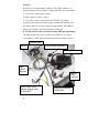
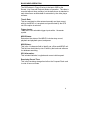
MDVR TYPICAL CONNECTION
The MDVR features a variety of connection points for various
accessories as shown in Figure 3 below:
Figure 1:
MDVR Connection Guide
The external connections feature:
• Camera audio and video input
• Camera 12V power output
• Video / Audio monitor output
• External magnetic attachment GPS Antenna
• Dual Audio inputs
• Main DB-25 Connector featuring:
–
–
–
–
4
Direct automotive power connection. The MDVR features an
internal resetable fuse.
5 trigger inputs.
1 record status LED output.
1 Open Collector trigger output.
MDVR main Harness wire connections
(25-pin connector)
Red – Power (direct 12 volt positive)
Black – Ground (12 volt negative)
Yellow – Ignition (switched 12 volt positive)
Green – Trigger 1
Orange – Trigger 2
Brown – Trigger 3
Blue – Trigger 4
Gray – Trigger 5
NOTE 1:
Trigger connections are pre-set (default) to activate on positive
Switching. They can be changed to negative switching by changing
MDVR settings in trigger Menu. (High = Positive / Low = Negative)
NOTE 2:
For correct operation, it is very important to connect the main power to a
constant 12V supply (not switched) and the Ignition trigger to the
ignition power supply (switched).
•
RCA to RCA 6 foot Cable # GSM70024
Monitor Video OUT to MDVR Video IN (use yellow connectors)
MDVR Video OUT to Monitor Video IN (use white connectors)
Red connector not used (see NOTE 3A below)
•
RCA to Camera input adaptor. (# GSM70026)
(Use yellow RCA connector - Red not used)
5
NOTE 3:
In order to view programmable settings on PT-VIDEO monitor, you
must use adaptor cables provided to connect MDVR video out to number
2, 3 or 4 camera inputs on the monitor.
(Cannot connect to camera 1 input.).
*** If you have a four-camera system (PT-VIDEO-4) you must
temporarily disconnect one of the cameras and attach the MDVR video
out cable in order to view the recorder settings and data. After MDVR
settings are confirmed, the camera must be reconnected.
(Leave this camera cable accessible for future MDVR programming)
The MDVR Data will not be viewable on cab monitor, but it will be
recorded and viewable when downloaded onto main computer system.
Optional GPS
MDVR
Camera input connectors
PT-VIDEO Monitor
Main
MDVR
Harness
MDVR Video out to
Monitor adaptor cable
# GSM70026
6
Monitor
Main
Harness
RCA to RCA Harness
# GSM70024
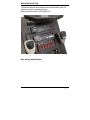
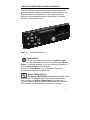
DIGITAL RECORDER FRONT PANEL OPERATION
The DVR features an illuminated keypad for easy operation in
dark environments. Below is a description of the functions of the
Digital Recorder front panel buttons. Some buttons will have
different functions depending upon if the recorder is recording,
stopped, or playing back video.
Figure 2:
Front Panel Controls
Power Button:
The unit is typically powered on by the Ignition trigger,
but may alternately be powered on by pressing the Power
Button. If manually powered on, the unit will remain powered on
until the Power Button is pressed again.
Holding the Power Button in for 10 seconds will perform a
hardware reset of the entire MDVR unit.
Search / Menu Button:
The Search / Menu Button accesses the recorded video
search menu. Pressing this button once brings up the search
menu. Holding this Search / Menu Button for greater than 3
seconds brings up the main system configuration menu where all
DVR functions can be changed and titles can be entered.
7
Left Arrow Key (mode dependant):
Pause & Playback Mode: Left Arrow Key adjusts fast
reverse playback speed up to 90x.
Right Arrow Key (mode dependant):
Pause Mode: Right Arrow Key adjusts the slow forward
playback speed from paused to 0.5x speed.
Playback Mode: Right Arrow Key adjusts fast forward playback
speed up to 90x.
Up Arrow Key (mode dependant):
Playback Mode: During standard 1x playback, Up
Arrow Key selects audio channel 1 to be output.
Down Arrow Key (mode dependant):
Playback Mode: During standard 1x playback, Down
Arrow Key selects audio channel 2 to be output.
Pause Button:
The Pause Button allows pausing of playback video and
resume play of video.
Stop Button:
The Stop Button stops playback of video and moves into
live view mode.
Record Button:
The Record Button begins recording of the video of the
selected channel.
8
BASIC MDVR OPERATION
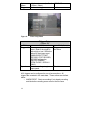
The OSD shown in Figure 5 below is the basic OSD for the
Record, Live View and Playback Modes of operation. The video is
recorded without these overlays, but the data shown is attached to
each video frame as Meta data for extraction by the video player
software.
Time & Date:
This time and date is either entered manually and kept current
with by the MDVR or is acquired and synchronized by the GPS
unit if the option is selected.
Trigger Inputs:
There are 6 user selectable trigger inputs with a 1 character
symbol.
MDVR Status:
Determines the status of the MDVR; includes stop, record,
playback and playback speed, and pause.
MDVR Name:
This is the 14 character field to identify car, officer and MDVR unit.
This field can be divided up into 3 fields by the back-end software
for database searching.
GPS Information:
This included Latitude, Longitude and current vehicle speed.
Remaining Record Time:
This is the remaining storage time left on the Compact Flash card
in units of hours: minutes.
9
Figure 3:
Basic OSD
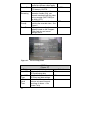
MDVR MENU STRUCTURE
MDVR Video Search Menu
The OSD shown in Figure 5 below is the video search menu used
for searching recorded video files on the Compact Flash card.
The column on the left shows the days with the column on the
right showing time in that day. A pound symbol in the right column
signals that record was triggered by an event.
10
Figure 4:
Recording Search Menu
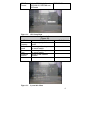
MDVR Main Menu
The OSD shown in Figure 8 below is the main unit menu. From
this menu access to all other setup screens is possible.
Figure 5:
Main Menu
11
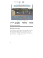
MDVR Setup Menu
Setup Menu
(Figure 9)
Field
Units
Action
Selection of English or Metric
units.
Default
English
Video Dwell
Time
Selects the time between video
switches. 0 seconds will allow a
trigger position to determine
camera input selected.
0 sec
Time Setup
Password
Setup
Advanced
Setup
Brings up the Time Setup menu.
Brings up the Password Setup
Menu
Brings up the Advanced Setup
menu
Figure 6:
Setup Menu
Time Setup Menu
(Figure 10)
Field
12
Action
Default
Date
Time
Daylight
Savings
Figure 7:
System date (assuming GPS
date is OFF)
System time (assuming GPS
time is OFF)
Automatic adjustment for
daylight savings time change.
Today’s Date
Today’s Time
ON
Time Setup Menu
Advanced Setup Menu
(Figure 11)
Field
Restore
Defaults
Erase Media
Menu
Password
Action
Restores the factory default
settings.
Permanently deletes all
recorded data from the selected
media.
Sets the password field or no
password for the menu.
Default
Title Setup
(Figure 14)
Field
Action
Default
13
System
Name
Trigger x
Figure 8:
14 character name (i.e. Car #
/ Officer / Other)
1 character trigger name
MDVR-CF
1-6
Titles Setup Menu
Trigger Setup
(Figure 15)
Field
Trigger 1-6
Speed
Action
Enter a name for the trigger
event / Enter if the trigger is
active high or low / Select the
action for the trigger event
(MARK EVENT, START
RECORD, STOP RECORD,
RECORD while active,
SWITCH CAMERA,
STEALTH REC, DISPLAY
ONLY)
Enable recording at a given
input speed.
Default
Trigger-x / Active H /
No Action
Disabled
All 6 triggers can be configured to one of seven actions. All
triggers are recorded in the meta-data. These actions are defined
below:
o MARK EVENT: Starts a recording if not already recording
and labels the recording as an event in the file name.
14
o
o
o
o
o
START RECORD: Starts a recording and will record until
the stop button is pushed on the front of the unit or the
storage media is full.
STOP RECORD: Stops a recording if the unit is recording.
RECORD: Starts a recording and records while the trigger
is active. Stops recording when the trigger is not active.
SWITCH CAMERA: Switches the camera input to the unit
based on the settings in the Setup Menu.
DISPLAY ONLY: Will display the trigger event on the OSD
and will record the trigger in the file meta-data.
Figure 9:
Trigger Setup Menu
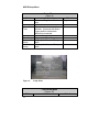
Record Setup
(Figure 16)
Field
Record
Mode
Image Size
Image
Quality
Action
STOP IF FULL or CONTINUOUS
RECORD
Selects the image resolution 640 x
240 / 320 x 240
Image quality selection of HIGH,
MEDIUM HIGH, MEDIUM,
MEDIUM LOW, LOW. Lower
Default
STOP IF FULL
320 x 240
MEDIUM
15
Frame Rate
Audio
Recording
Priority
Prompt
Total Time
Figure 10:
image quality provides longer
record time at lower video quality.
Selects the frame rate from 30
FPS down to 1/8 FPS.
Selects whether to record 2
channels of audio (ON), one
channel associated with the video
being recorded (SWITCHED) or
no audio (OFF).
ON / OFF: Selects whether to
prioritize the recorded video. See
Figure 6
Displays the recording time
capacity based on the Compact
Flash card size and record
settings above.
30 FPS
ON
OFF
Record Setup Menu
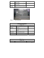
GPS Setup
(Figure 17)
Field
Use GPS
Use GPS
Time
UTC /
Local
Time
16
Action
Selects whether to utilize the
GPS positioning data.
Selects whether to utilize the
GPS time and date settings.
Selects the difference
between universal time and
local time (in hours – 6 for
Central Time).
Default
YES
YES
-6
GPS Data
Format
Selects GPS display format:
DDD:MM:SS, DDD:MM.mm,
DDD.dddd
Figure 11:
GPS Setup Menu
System Info
DDD:MM:SS
(Figure 18)
Field
Disk
Capacity
Percent
Used
Percent
Free
Firmware
Version
Figure 12:
Action
Storage capacity of the record
media.
Percentage of used space on
the record media.
Percentage of free space on
the record media.
Version of the installed
firmware.
Default
System Info Menu
17
MDVR Password Menus
The menus shown in Figure 19 below allow for configuration of the
units password access. All buttons on the front of the unit may be
used for password access EXCEPT THE POWER BUTTON. The
password field consists of 6 characters with a default password of:
“Left Arrow”, “Right Arrow”, “Left Arrow”, “Right Arrow”, “Left
Arrow”, “Right Arrow”. After this sequence is entered, the system
allows access for 30 minutes (or after cycle power) before the
password is enabled again.
The unit supports 4 levels of password protection with the ability to
enable any or all levels. These are defined below:
o All Keys: Any key press required a password.
o Power-off: The Power button requires a password.
o Playback: Video playback requires a password.
o Menu:
Access to the menus requires a password.
Figure 13:
18
Password Menus
COMPACT FLASH FILE STRUCTURE
In the root directory of the Compact Flash card, the DVR will create a
new subdirectory for each day of recording. The subdirectory is named
as follows:
Mmm.dd.yyyy
Mmm = 3 letter month abbreviation, e.g. Jan, Feb, Mar, ...
Dec
dd = day (01 - 31)
yyyy = 4 digit year, e.g. 2006
Each subdirectory will contain one or more AVI files named as follows:
ssssssssssssss_Mmm.dd.yyyy_hh.mm.ss.avi
sss.. = User defined system name. This name can be from 0
to 14 characters in length. This field is free-form for
the end user to define car number, officer name,
whatever within the 14 character limitation. The user
is free to put spaces within this name, but these are
replaced with underscores ('_') in the filename.
Mmm.dd.yyyy = same as directory name
hh.mm.ss = 24 hour time in hours, minutes, and seconds
.avi
= AVI file extension
NOTES:
. If the system name is 14 characters in length, then there
is no trailing underscore after the system name.
. File names can contain a 'suffix' which indicates that the
file is a continuation of a recording (every 10 minutes, the
DVR starts a new file). Also, an event can be marked with
a suffix. The suffixes are:
'+' : this is a continuation file
'#' : this file contains an 'event' of interest
The suffix is placed just prior to the file extension, e.g:
Jan.01.2006_01.00.00.avi /* First file
*/
Jan.01.2006_01.10.00+.avi /* Continuation file */
Jan.01.2006_01.12.15*.avi /* Event file
*/
19
BACK PANEL CONNECTIONS
Main Interface Connector
25-pin DSUB
Pin #
Function
1
Record LED Out; 3.3V with
a 1k series resistor.
2
3
12V Camera Output
Trigger In 1
5
6
7
8
9
10
Trigger In 2
Remote power on / Ignition
Trigger In 3
Trigger In 4
Trigger 5
AUX 12V Output w/
100ohm series resistor.
Trigger 6 / Mic Trigger In on
8-pin Molex.
11
14
15-16
4, 12, 13,
17,18, 25
19
20
21
20
Spike protected Automotive
Power Output.
Automotive Power Input
Automotive Ground
RS232-RX 4
RS232-TX 4
RS232-RX 3
22
23
24
25
RS232-TX 3
RS232-RX Radar IF
RS232-TX Radar IF
Ground
Notes: 1. Pins 23 & 24 are dedicated to the Radar Interface
Only.
2. Pin 11, Trigger 6 / Mic Trigger Input are also
connected to pin 4 of the 8-pin Molex.
Use only one or the other.
3. Pin 14 is protected automotive output power which
could range from 10V to 26V.
Camera Power Connector
2-pin Molex 43650-0200
21
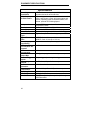
EQUIPMENT SPECIFICATIONS
Specifications
Recording
Capabilities
Meta-Data Capture
for Each Frame
NTSC video camera input up to 30 fps with
synchronized audio and meta-data.
Input voltage, unit temperature, 14 character unit
name, panic button events, all triggers status and
names, operating mode & version numbers, time
& date, optional GPS lat/long/speed.
Compression
Motion JPEG compression w/ 5 selectable
compression ratios.
Selectable 640 x 240 or 320 x 240.
Selectable 30 FPS to 1/8 FPS.
Standard AVI playable in Windows Media Player.
Type 1 Compact Flash Card support up to 32GB.
Resolution:
Frame Rate:
Video File Format
Archive Media
Type:
Typical Record
Time
Power Supply
Input Rating
On Power
Consumption w/o
Cameras
Off Power
Consumption
12V Camera Power
Output Max
External Trigger
inputs:
External signal
outputs:
Transient
Protection
Operating
Temperature:
Operating Shock:
Unit Weight:
Unit Size:
22
4GB CF Card: 4.6 hrs up to 6.6 hrs.
8GB CF Card: 9.2 hrs up to 13.2 hrs.
Standard automotive power range; 8 – 24 Volts.
< 270 mA
< 10 mA
12V @ 1 Amp regulated switched power outputs.
6 input triggers plus the ignition trigger.
1 LED driver, 1 Open Collector output.
2500 Watts for 10ms
-20 C ~ 60 C (- 4 F ~ 140 F) ambient temperature.
1,000Gs being equivalent to a five-foot drop.
1.4kg (3.0 lbs)
7 in (178 mm) x 2 in (51 mm) x 8 in (203 mm);
1DIN Mountable