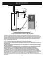
1
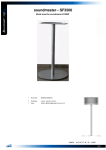
Installation & Operating Manual The Harman SF1500A, SF2500A, SF2600A, SF 3500A R4 SAFETY NOTICE Please read this entire manual before you install and use your heating appliance. Failure to follow instructions may result in property damage, bodily injury, or even death. FOR USE IN THE U.S. AND CANADA. Not SUITABLE FOR INSTALLATION IN MOBILE HOMES IF THIS HARMAN STOVE IS NOT PROPERLY INSTALLED, A HOUSE FIRE MAY RESULT. FOR YOUR SAFETY, FOLLOW INSTALLATION DIRECTIONS. CONTACT LOCAL BUILDING OR FIRE OFFICIALS ABOUT RESTRICTIONS AND INSTALLATION INSPECTION REQUIREMENTS IN YOUR AREA. Contact your local authority (such as municipal building department, fire department, fire prevention bureau, etc.) to determine the need for a permit. Cette guide d’utilisation est disponible en francais. Chez votre concessionnaire de Harman Stove Company. save these instructions. R1 Table of Contents Packing List 3 Installation 5 Mounting Blower & Filter Box 7 Wiring 8 Duct Work11 Operation11 Safety Tips13 Chimney Troubleshooting13 Maintenance14 Specifications 15 Coil Installation16 Oil Burner Setup18 Warranty19 Packing List - SF2600 Blue Angel Oil Burner Burner Gasket Automatic Draft Control Blower (2) Blower Brackets Filter Box Kit (3 pieces) + Filter Fan Control / High Limit 3-Speed Fan Switch (not on SF3500) (2) Thermostats (2) Junction Boxes Relay High Limit Snap Disc (4) 1/4 X 3/4 bolts & (4) Filter Box Mounting Clips 36” Flex Conduit (1) Straight Conduit Fitting (1) Elbow Conduit Fitting Ash Pan Shaker Handle Owner’s Manual Warranty Registration Filter Filter Box Kit Filter Box Mounting Clips Blower Snap Disc Automatic Draft Control Blower Brackets Fan Control / High Limit 3- Speed Fan Switch Thermostats Relay Oil Burner Gasket Oil Burner Ash Pan Shaker Handle Junction Boxes Flex- Conduit and Fittings Packing List for SF1500, SF2500 & SF3500 Blower Mounting Plate w/ 2= 5/16X3/4 bolts ( SF3500 Only) Automatic Draft Control Blower (2) Blower Brackets Filter Box Kit (3 pieces) + Filter Fan Control / High Limit 3-Speed Fan Switch (not on SF3500) Thermostat Junction Box Relay (4) 1/4 X 3/4 bolts & (4) Filter Box Mounting Clips 36” Flex Conduit (1) Straight Conduit Fitting (1) Elbow Conduit Fitting Ash Pan Shaker Handle Owner’s Manual Warranty Registration Filter Filter Box Kit Filter Box Mounting Clips Blower Automatic Draft Control Blower Brackets Fan Control / High Limit 3-Speed Fan Switch Thermostat Relay Blower MountSF3500 only Ash Pan Shaker Handle Junction Box Flex Conduit & Fittings Furnace Installation To ensure a safe installation, it is recommended that this furnace be installed by a qualified installer. The sheet metal top and sides can be easily removed to reduce the chance of dents or scratches on the painted surfaces. To remove the sheet metal, first lift off the top section. Now, the sides can be removed by lifting up and out away from the furnace. Inspect Gasket prior to reinstalling heat exchanger. To lighten the SF2600, the oil burner heat exchanger should be removed. Do so by first removing the sheet metal as described above. Remove the front sheet metal by first removing the burner collar. Now remove the the two long bolts on each side of the heat exchanger.(Figure B) The entire unit can now be lifted off and moved separately. Caution: This furnace must not be installed closer than 24 inches at the sides and 30 inches from the rear to Figure A combustible materials. The unit may only be installed on a non-combustible floor surface such as concrete floor or concrete pad on dirt floor. The hot air plenum must be a minimum of 2 inches from the ceiling or other combustibles above the plenum. Locate the furnace as close to the chimney as possible while still maintaining the above clearances. No more than 8 feet of stovepipe should be used, including two or less 90° elbows. All horizontal runs of pipe should have a minimum 1/4 in. rise per foot. All stove pipe must be 24 gauge or thicker. When re-installing the heat exchanger, inspect the gasket around the furnace opening, and replace if necessary. (Figure A) Place the heat exchanger in position and secure with the long bolts and nuts. Be sure the gasket is compressed evenly. Re-install the sheet metal by sliding the groove on the bottom of each side panel over the steel lip on the furnace. The top sheet metal piece holds the sides in place. The SF2600 front cover gets installed by angling the bottom edge over the lip on the top of the firebox. The side edges must slide into the grooves on each side and pushed in flush with the sides and top. This front piece is held in place by the black ring which gets tightened around the burner pipe. Do not over tighten as this will push the sheet metal in too far. (4) 12in. bolts, two on each side, attach the heat exchanger to the furnace. Figure B Furnace Installation Installing Wood/Coal High Limit Switch- SF2600 only. First, install the sheet metal sides as described in the previous section. Install the snap disc switch into the hole on the right side sheet metal. Then mount the open backed junction box around the snap switch. Proceed with wiring as shown on page 10. Also refer to Figure D. in this section. Mounting The Oil Burner- SF2600 only. Remove oil burner unit from it’s box. Loosen the four bolts in the pipe on the front of the furnace. Insert the nose of the oil gun into the pipe. Before sliding the oil burner all the way in, apply the gasket around the nose of the oil gun by wrapping it around the nose. Next, slide the oil burner into the pipe and secure it by tightening the four bolts around the collar. Be sure to tighten the bolts evenly to locate the oil burner in the center of the pipe. The final set-up of the oil burner should be done by an experienced oil burner technician with the proper equipment. Refer to the SF2600 wiring diagram on page 10 and the oil burner manual for proper burner set-up. There is also a section at the end of this manual with specific oil burner instructions. Venting Guidelines. SF1500, SF2500, SF3500. Your Harman hot-air furnace must be vented to it’s own separate flue-lined “Class A” chimney, not less than 8” X 8” in size. The chimney must be capable of providing a draft reading of at least .06” water column on a draft meter, in order to function properly. The Chimney must be a minimum of 16 ft. high, and must be two feet higher than anything within 10 ft. The chimney must also be at least 3 ft. higher than the point at which it exits or passes by the roof. A barometric damper must be installed in the flue to eliminate excessive draft. Any horizontal sections of connector pipe must have at least 1/4 in. per foot rise. Limit the number of elbows to two or less. All joints in the connector pipe must be secured with sheet metal screws. This figure represents the models; SF1500, SF2500, and SF3500. It’s intention is to represent the approximate location of the various controls. This drawing may also be used as a recommendation for routing of the wiring and approximate dimension of control spacing. Please note that this drawing is for reference only. Each specific installation will vary. Assembly. Bolt the shaker handle to the block on the lower left side of the furnace, using the bolts and lock-washers provided. Bolt the two manual draft controls to the front load door. Proper installation allows the draft controls to open approximately 1/2” from the door surface. See Figure 1. Bolt the automatic draft control to the bottom door. Be sure to hold the unit straight while tightening. After the automatic draft control is mounted, the two wires must be strung through the flexible conduit and two fittings supplied. The knockout plug of the junction box must be removed to install the conduit fitting. Check the door of the automatic draft control to assure proper operation. Warning: Keep pieces of wood or coal out of the draft door opening mechanism, as this could cause the door to stick. NOTE: Oil the hinge at the begining of the heating season with a light oil. The junction box is best mounted on the side of the furnace about 1 in. back and 8 in. from the top of the sheet metal side. (fig. C or D) If this location is inconvenient, anywhere on the right side will work. Furnace Installation SF2600. This figure represents the model SF2600 furnace. It’s intention is to represent the approximate location of the various controls. This drawing may also be used as a reference for wiring and control spacing. Please note that this drawing is for reference only. Specific installations will vary. Mounting The Blower And Filter Box Position the filter box between the brackets on the rear of the furnace, with the bottom of the box resting on the flange at the bottom of the furnace. Insert the mounting clips into the bracket slots to secure the filter box. (see Figure 2) Next, install the blower brackets onto the blower being sure to install the rubber feet into the brackets. NOTE: On the SF3500, install the blower mount and blower before the filter box. All hardware, brackets, etc. for the blower, will be found in the carton with the blower. Next, position the blower in the filter box, centered behind the inlet hole and allow approximately 1/8 in. space between the rear of the furnace and the blower outlet. Now, install the filter rail onto the filter box. NOTE: The filter rail is best installed on the side toward the shaker handle, so that any pipes from the hot water coil do not interfere with filter installation or removal. NOTE: Before proceeding with the installation of the access door, it is suggested that the wiring be completed. The access door is installed by slipping the flange on the bottom of the access door over the bottom rail of the filter box opening, then push the top of the door against the top of the filter box opening and secure with a sheet metal screw. Figure 2 Filter box mounting clips 1/8 in. space between blower and furnace Furnace Installation - Wiring Wiring Before beginning any wiring, study the appropriate wiring diagram for your unit. Also refer back to figures C or D for an example of what the completed job will look like. It is your reponsibility to follow all state and local electrical codes. Locate the best place to route the power for the blower, and drill a 7/8” hole in the filter box. This hole size will accomodate a “romex” connector. Attach the blower and power wires as shown on the appropriate wiring diagram. Once you have the plenum installed, the fan control with high limit switch can be installed. The Fan control/high limit switch is packaged with a jumper between the two sets of terminals inside. REMOVE THE JUMPER WIRE INSIDE THE FAN CONTROL. The fan control should be installed in the right side of the plenum and 12 to 18 inches above the top of the furnace. A separate conduit should be run from the fan control to the junction box. Mount the thermostat in a central location of the area you want to heat. Run two wires to the junction box, from the heating terminals on the thermostat. 22 gauge or thicker wire is acceptable. The next step is to run a 120 volt line from your breaker panel to the junction box. Attach all wires according to the corresponding wiring diagram, and install the relay into the junction box. DO NOT TURN ON THE BREAKER UNTIL ALL WIRING IS COMPLETE AND THE RELAY IS SECURED. SF1500 and SF2500 Wiring Diagram SF3500 Wiring Diagram SF3500 Wiring Diagram SF2600 Wiring Diagram SF2600 Wiring Diagram 10 Duct Work and Operating Instructions Duct Work. This figure shows a typical duct system layout. Be sure the entire system is properly sized to provide the correct static pressure for optimum blower Return Air performance. Have any new duct system designed by a HVAC professional. Supply Trunk Plenum Operating Instructions Adjusting Automatic Draft Control - In order for your new furnace to function, the controls must be properly adjusted. The heat output is regulated by the automatic draft control, on the bottom door of the furnace. Refer to the illustrations at right; The electric draft motor (A) opens and closes the flapper door (B). The flapper door opens to feed more air to the fire and closes to reduce the air to the fire. The maximum air flow can be adjusted by turning the adjuster bolt (C) counter-clockwise for more air and clockwise for less air. NOTE: To preserve motor life, all adjustments of this bolt should be done while the flapper door is in the closed position. The idle adjuster (D) controls the minimum amount of air that enters the firebox when the flapper door is closed. Adjustment is made by turning the adjuster vertical for zero air, or horizontal for maximum idle air. It is best to start at a medium setting as shown at right. Figure 6 Adjusting the fan control- Shut off the power at the circuit breaker before removing the fan control cover. Make sure the copper jumper (circled below) is removed before using the furnace. Note the three pointers on the dial. The one on the right is the high limit adjustment. Pre-set at 200 degrees, it’s function is to close the automatic draft control flapper door if the temperature in the plenum reaches 200 degrees. Do not change this setting. The center pointer adjusts the temperature at which the blower starts. A good initial setting for this is 150 degrees. The pointer on the left is to adjust the temperature at which the blower stops. A good initial setting for this pointer is 100 to 110 degrees. If it is set too low, the air will feel cool coming out of the registers at the end of the blower cycle. Thermostat- Set the thermostat to the desired temperature. When more heat is needed, the thermostat opens the automatic draft control flapper door. This allows air into the firebox, which raises the output of the fire. When the temperature in the plenum reaches the set temperature of the center pointer on the fan control, the blower will begin blowing heated air through the Figure 7 ductwork. When the thermostat reaches it’s setpoint, the automatic draft control closes the flapper door, thus, reducing the output of the fire. As the temperature in the plenum drops to the set point of the left pointer on the fan control, the blower will stop. A solid fuel fire cannot cease output immediately, therefore, your room temperature may exceed the thermostat setting at times. You also may notice times that the blower runs for a short period even though the draft control is closed. Again, you can’t just stop a wood or coal fire instantly, and temperature may build enough to run the blower. This is normal and will be noticed more with coal than with wood. 11 Figure 5 ZERO MED MAX Operating Instructions SF 2600 - Oil Operation as Backup - furnaces may be loaded with wood as full as possible for high output and long burn time. Then close the door and allow all the wood to catch fire. The bottom door may again be opened to speed the process. The object is to get the wood burning well enough so it will not go out when the automatic draft shuts back to the idle setting. NOTE: When the bottom door is open, the automatic draft cannot function to reduce the amount of air to the firebox. For this reason, the furnace could overheat. The SF 2600 offers a unique option to the homeowner. The ability to have an efficient oil backup heat source built right into a wood/coal furnace. The operation of the oil burner as a backup system is as simple as setting a thermostat. To use the oil portion of your furnace as a backup proceed as follows: 1. Set the wood/coal thermostat to the comfort level you desire. 2. Set the oil thermostat to a level 5 to 10 degrees but not less than 3 degrees lower than the wood/coal thermostat. That’s all there is to it. The idea is that when the wood/ coal portion can no longer maintain the level set on that thermostat the oil portion will come on and maintain the temperature set on the oil thermostat. WARNING: NEVER LEAVE THE BOTTOM DOOR OPEN WHILE FURNACE IS UNATTENDED! After the wood is burning well, close the bottom door. The automatic draft control will now regulate the fire. The idle control (as shown on Fig. 6) on the flapper door must be adjusted so the fire does not go out or overheat. Experience will dictate the best setting. Normally the two manual draft controls on the loading door are kept closed to burn wood. SF 2600 - Oil Operation Only - In the oil only mode, simply turn the wood/coal thermostat to its lowest setting and select the comfort level you desire on the oil thermostat. The SF 2600 will now act as a standard oil burner and maintain your chosen temperature. NOTE: It is recommended that the wood/ coal fire in the lower portion of the furnace be out or nearly out before going to “oil only” operation. Starting A Coal Fire • Use the same procedure as for wood except do not go to large diameter wood. Use wood about 2” in diameter maximum. This size will form very hot wood coals in less time. Here again, the bottom door may be opened to speed the process. When a substantial bed of red wood coals are developed, start adding a thin layer of coal. Pea or nut sized coal is better for starting a fire than stove coal. When the first layer is burning with some blue flame, continue to add thin layers of coal until there is a solid bed of burning coal. Let each layer burn a blue flame before adding another layer. Layers can be added until the bed is approximately ten inches deep. This is about at the top of the firebrick. Most users find that if they keep the two manual draft controls open about one quarter turn, it helps keep the gasses burned off. NOTE; Close the bottom door as soon as the desired coal bed is made. Curing Paint - During the first few hours of burning, a blue smoke will be observed rising from the painted surface of the furnace. It is advisable to increase the amount of fresh air in the room during this breaking-in period. This may be achieved by opening doors, win dows, etc. Don’t be alarmed. This is normal. Starting a Wood Fire - Open the bottom door to increase the draft. Take about eight sheets of newspaper, crumbled into balls and place on top of the grates. Next, lay some fine kindling on top of the paper. This kindling must be dry and no larger than 3/4” diameter, and should be layered in a criss-cross pattern to allow good air flow. Then, lay some slightly larger pieces (2” diameter) of wood on top of the kindling. Light the paper at the bottom just inside the door. Now close loading door and allow kindling and wood to catch fire. After about five minutes, close the bottom door and open the loading door an inch or two for a few seconds before opening completely. This method will allow the smoke to clear away from the door opening. Now the fire should be well established and ready for some larger wood. Add four or five pieces of 3” to 4” diameter wood. Close loading door and open bottom door again. Let burn for about 5 minutes. Now open loading door using the same method as before, always closing the bottom door before opening the top door. Now load the firebox with wood to the desired fullness. All Harman Loading - Coal should never be added unless there is a reasonably hot fire. The coal bed should be bright and vigorous. If the fire is burning hot and there is a deep bed of coals, full loads of coal can be added at any time. However, if there is not a deep bed of coals, it is best to add small amounts of coal at first. Shaking - Shaking should be done only when there is a well-established fire. The frequency of shaking will depend on the degree of burning. Shaking should be done whenever the furnace is refueled. Best results for shaking Harman grates will occur when short choppy strokes are used rather than long even strokes. 12 Operating Instructions/Safety Tips nace into the room with possible fatal consequences. With the exception of start up or increasing heat from a low fire, or removing ashes, the bottom door should be kept closed. Never install a Harman furnace to a chimney with a history of down drafts. KEEP CHILDREN AWAY - MAY CAUSE SERIOUS BURNS. The amount of shaking is critical. Too much will disrupt the fire bed and too little will restrict the air flow. The proper amount normally occurs when red coals first start to drop through the grates into the ash pan. Ashes - Ashes should never be allowed to accumulate in the ash pit so that they in any way impede the flow of combustion air to the fire. Excess ash accumulation can cause the fire to go out and also can cause severe damage to the grates because of the absence of a cooling flow of air beneath them. Ashes should be placed in a metal container with a tight fitting lid. The closed container of ashes should be placed on a noncombustible floor or on the ground, well away from all combustible materials, pending final disposal. If the ashes are disposed of by burial in soil or otherwise locally dispersed, they should be retained in the closed container [outside the dwelling) until all cinders have thoroughly cooled. CAUTION: ASHES SHOULD NEVER BE ALLOWED TO ACCUMULATE ABOVE THE TOP OF THE ASH PAN. ASHES IN CONTACT WITH THE BOTTOM OF THE GRATES ACT AS AN INSULATOR, INTENSIFYING THE HEAT ON THE GRATES, AND COULD CAUSE THEIR WARPAGE. WITH AN EXCESSIVE ASH BUILDUP, PRIMARY COMBUSTION AIR IS RESTRICTED. THUS THE UNIT’S OUTPUT COULD BE REDUCED. Coal produces considerably more ash than wood. So the intervals between emptying are much shorter. For equal heat output,coal will produce seven to ten times more ash than wood. CAUTION: ALL SURFACES OF FURNACE ARE HOT. DO NOT TOUCH. KEEP CHILDREN AWAY. SERIOUS BURNS WILL RESULT IF TOUCHED. THIS IS A HEAT PRODUCING APPLIANCE. FUEL/FIRING WARNINGS DANGER! FIRE HAZARD! DO NOT USE CHEMICALS OR FLUIDS TO START OR “FRESHEN UP” A FIRE. SEVERE BODY BURNS OR A FIRE IN YOUR HOME COULD RESULT. DO NOT BURN GARBAGE, GASOLINE, THINNERS, DRAIN OR ENGINE OIL, KEROSENE, OR FUEL OIL, ETC. AN EXPLOSION, A HOUSE FIRE OR PERSONAL INJURY COULD RESULT. KEEP ALL SUCH LIQUIDS WELL AWAY FROM THE FURNACE WHILE IN USE. Chimney Problems Not Enough Draft - Chimney is too low. A chimney should be two feet higher than anything ten feet around it. Air may be leaking in around a loose fitting clean-out door, flue pipe may not be tight at joints, or the masonry may be defective. Chimney may be blocked with creosote or bird nests, etc. Improper sized chimney or stovepipe. Too many elbows. Distance of more than eight feet between furnace and chimney. Draft Control Settings - The idle air adjustment on the flapper door may need to be adjusted slightly less for coal than for wood. Here again, experience will dictate the best setting. The maximum air adjustment bolt can be set at the maximum position for quick recovery. When a longer than normal burn time is desired, the maximum air adjustment can be reduced. Never adjust the maximum air bolt when the flapper door is opened. See Fig. 6 on page 11. Down Drafts - Trees or other topographical barriers may impede the chimneys operation causing a down draft condition to exist. This can also be caused by adjacent buildings or chimneys. Safety Tips Creosote and Condensation - If creosote or condensation runs out of the chimney or stovepipe, check the following. Chimney cap or lining may be defective. Furnace may be too far from chimney, not allowing the chimney to get warm. Wood being burned may be green or wet. Unit may be too large for home causing wood to be burned too slow. When opening the loading door, it should be cracked open slightly for a few seconds to allow oxygen to burn any gases that may be present and to allow smoke to be drawn away from the door. Whenever the bottom door is open, it should be closed before opening the loading door. This is to increase draft through the loading door and prevent excess smoke from escaping. The firebox should never be filled with excessive coal so that the flue exit is blocked or impeded in any way. Burn ing coal generates carbon monoxide. If the flue gas exit is blocked, the carbon monoxide can be forced out of the fur Excessive Draft - This can be controlled with a barometric draft control on the stovepipe. 13 Maintenance Maintenance The spiral chamber is basically self-cleaning. However, if there is a draft problem and you have been burning wood for a long time with little heat demand, the spiral chamber may need cleaning. Soft coal will also require more frequent cleaning. To clean, remove stovepipe and scrape the creosote from the front and top of the chamber and remove. The rear of the chamber will not accumulate creosote. NOTE: 1/8” to 1/4” of creosote in the spiral chamber is normal. Creosote can be burned off by burning coal for a few days. Firebricks may become cracked during the course of normal operation. A cracked brick that is still in place is still doing its job and need not be replaced immediately. If a brick is broken and has fallen out of place, it should be replaced immediately. The firebrick used in the Harman furnaces are inexpensive and easy to replace. The blower manufacturer recommends the blower motor to be oiled once a year with 10 to 20 drops of light weight oil [check instructions packed in blower box). Cleaning Heat-Exchanger (SF2600 Only) - Remove oil burner by removing four mounting bolts, Burner can be tied up to ceiling to avoid having to remove the wiring. Next, remove the collar from the front cover and remove front cover by tilting out from top first. Now the heat exchanger will be exposed. Next, remove the four nuts that hold on the cover, then remove the cover. This will expose the inside of the heat exchanger. Remove spirals by simply pulling them out and clean the tubes with a brush. Reinstall spirals so they are flush with the end of the tube and reassemble unit in reverse of disassembly. 14 Warranty Warranty is issued at time of purchase. For the warranty to become effective, you must return the activation coupon to Harman, 352 Mountain House Rd., Halifax, Pennsylvania 17032 as soon as possible. The model/ serial number is found on the front, upper-left corner of stove. WARRANTY WILL NOT BE HONORED UNLESS THE FORM IS COMPLETED IN ITS ENTIRETY!! Your Signature is Required!! Harman furnaces are warranted for five years in accordance with the warranty terms. Exclusions to the five years will be the following items: A. Electrical Blower (1 year warranty) B. Door Packing C. Glass D. Firebricks E, Paint F. Any damage deemed abuse See a complete copy of the warranty on page 19. Specifications Heating Capacity- square ft. SF1500 SF2500 SF2600 SF3500 Complete Complete Complete Complete 2200 3200 3200 4200 90,000 120,000 120,000 170,000 Blower Size 1000 cfm 1000 cfm 1000 cfm 1450 cfm Automatic Draft Standard Standard Standard Standard Filter Box & Filter Standard Standard Standard Standard 3-Speed Fan Switch Standard Standard Standard Single Speed Fan Control / High Limit Standard Standard Standard Standard Thermostat Standard Standard Standard Standard Domestic Hot Water Coil Optional Optional Optional Optional Approximate BTU Input Firebox Dimensions - Inches 16Wx22Lx20.5H 18Wx26Lx21.5H 18Wx26Lx21.5H 18Wx30Lx25H Recommended Log Length 18 in. 22 in. 22 in. 27 in. Maximum Log Length 22 in. 26 in. 26 in. 30 in. Flue Size 6 in. 7 in. 7 in. 7 in. Filter Size 14 X 20 14 X 20 14 X 20 14 X 20 4 5 5 6 Weight 580 Lbs. 700 Lbs. 900 Lbs. 800 Lbs. Plenum Dimensions Number of Grates 20 X 20 20 X 20 20 X 25 20 X 25 Clearance to Combustibles- Rear 30 in. 30 in. 30 in. 30 in. Clearance to combustibles- Side 24 in. 24 in. 24 in. 24 in. A: 25 in. 26 in. 28 in. 28 in. B: 20 in. 20 in. 20 in. 20 in. C: 46.5 in. 47.5 in. 57 in. 52.5 in. D: 27.75 in. 31 in. 31 in. 36 in. E: 20 in. 20 in. 25 in. 25 in. F: 40 in. 41.75 in. 40.5 in. 45 in. G: 16.5 in. 16.5 in. 16.5 in. 16.5 in. H: 44.5 in. 47.5 in. 48 in. 52.5 in. K: 27.5 in. 27.5 in. 27.5 in. 27.5 in. Dimensions: A B D E G C F K H Special Instructions Coil Installation: Hot Water Out Cold Water In Pressure Relief Valve Automatic Air Valve 2 1 5 Pressure Relief Valve (Must be within 2 feet of coil) 3 Existing Water Heater 3 Rear Of Furnace 10 Feet Maximum Drain Valve 4 Plumbing Diagram For Thermo-Siphon Method - Maximum Distance = 10 Feet Place one of the supplied nuts on each leg of the coil. Place the coil through the holes on the back of the furnace, and adjust the nuts so that the pipes stick out about 1¼ to 1½ inches from the rear of the furnace. Place the flat washers and gaskets over each pipe and tighten the nuts. You are now ready to run the piping. This simple method is the most economical. However, the existing water heater must be less than 10 feet from the furnace. The water inlet, where the Temperature / Pressure Relief valve is located, must be higher than the top leg of the water coil. The water heater should be elevated, if necessary, to allow for proper thermo-siphon action.(The method by which hot water will circulate automatically through the system.) A. Shut off the water heater and the water supply to it. Drain the tank completely. B. Remove the Temp. / Presure relief valve and discard. Install a short 3/4 in. nipple and tee (1) along with a new relief valve. C. run 3/4 in. copper tubing between the water tank and the top leg of the coil. Install a 3/4 in vent elbow and automatic “float type” air vent (2) in the high point of the line. Within 2 feet of the top leg of the coil, install a 150 lb. pressure relief valve (5). Run 3/4 in. tubing from the release exit of both relief valves downward (3) so the hot water can escape in the event of an overheat situation. D. Remove the drain valve, at the bottom of the tank. Install a short 3/4 in. nipple and tee and reinstall the drain valve to the tee (4). Run 3/4 in. tubing between the drain / tee combination and the lower leg of the water coil. After all of the connections are secured, refill the water tank. Turn on the water heater only after the tank has been completely refilled. 16 Special Instructions Cold Water In Hot Water Out Aquastat, close on rise. Optional Temp. / Pressure Relief Valve Automatic Air Valve 8 2 1 Pressure Relief Valve - Must be within 2 ft. of coil 7 3 3 Drain Valve 5 4 Optional Gate Valve to Control Rate of Flow 6 Circulator Pump Distance between of more than 10 feet Circulating Pump Method - Distance = 10 Feet or More This method is used when the water heater tank is more than ten feet away from the furnace or the furnace is on a higher level than the water heater tank. In addition to a circulator pump, you may want to add a aquastat to thermostatically control the pump according to water temperature. This is optional and not necessary if the circulator pump is left run continuously. Another option is a gate valve placed near the pump to control the rate of water flow. A. Shut off the water heater and the water supply to it. Drain the tank completely. B. Remove the Temp. / Presure relief valve and discard. Install a short 3/4 in. nipple and tee (1) along with a new relief valve. C. Remove the drain valve, at the bottom of the tank. Install a short 3/4 in. nipple and tee and re-install the drain valve to the tee (4). D. Install a circulating pump as shown (6). Run 3/4” copper tubing from the circulating pump to the lower leg of the water coil. This is where the optional gate valve (5) can be installed to regulate flow. E. Install a 3/4 in. tee and a 150 lb. Pressure relief valve (7) in the top leg within two feet of the coil. F. Complete the 3/4 in. line by running it back to the tee at the top of the water heater tank. Be sure to install the 3/4 in. vent elbow and automatic air vent (2) at the high point of the line. The optional aquastat can be installed in this line, a maximum of 6 feet from the furnace. This aquastat must close on rise in temperature and must be hooked up to turn on the circulator when the water temperature reaches 120° f. G. After securing all connections, refill the tank with water and then, ONLY THEN, turn on the power to the water heater. 17 SF2600 Burner Set Up SF2600 Oil Burner Setup Nozzle Off Cycle Damper Setting (B) Flamelock Setting (A) Combustion Air (C) Draft - (Inches of water column) 80 Degree Solid Cone No.1 (as low as it goes No. 1 No. 1 to 1¼ .06 to .08 Tests for CO² must be made without a fire in the wood/ coal firebox, and with all doors and draft controls completely closed. The burner should be fired for several minutes prior to taking a reading. Normal CO² reading is 11 to 12 with a stack temperature of 300 degrees or less. This would give you an efficiency of 84 to 85 percent. 7¾” 12½” 7” 12⅞” 18 1 Year Limited Warranty (Commerical) 5 Year Limited Warranty (Residential) Warranties are not transferable. Harman Stove Company warrants its products to be free from defects in material and workmanship, in normal use and service, for five (5) years from the date of sales invoice. If defective in material or workmanship, and if removed by the owner with in 60 months of installation, Harman Stove Company will, at its option, repair or replace the product as described below. The warranty above constitutes the entire warranty with respect to Harman Stove Company product. HARMAN STOVE COMPANY MAKES NO OTHER WARRANTY, EXPRESS OR IMPLIED, INCLUDING ANY WARRANTY OF MERCHANTABILITY, OR WARRANTY OF FITNESS FOR A PARTICULAR PURPOSE. No employee, agent, dealer, or other person is authorized to give any warranty on behalf of Harman Stove Company. This warranty does not apply if the product has been altered in any way after leaving the factory. Harman Stove Company assumes no liability for “resultant damages of any kind” arising from the use of its products. In addition, the manufacturer shall be held free and harmless of liability for damage to property related to the operation, proper or improper, of the equipment. THERE ARE NO OTHER WARRANTIES WHICH EXTEND BEYOND THE DESCRIPTION ON THE FACE HEREOF. THESE WARRANTIES APPLY only if the device is installed and operated as recommended in the user’s manual. THESE WARRANTIES WILL NOT APPLY if damage is caused by abuse, accident, improper installation, negligence, or use beyond rated capacity. SERVICE LABOR RESPONSIBILITY - In furnishing replacement parts, Harman Stove Company assumes no responsibility for any labor expenses, for service removal or reinstallation. HOW TO MAKE A CLAIM - Any claim under this warranty should be made to the dealer from whom this appliance was purchased. Then contact is made with the manufacturer, giving the model and serial numbers, the date of purchase, your dealer’s name and address, plus a simple explanation of the nature of the defect. SHIPPING COSTS - The transportation charges are as follows: (1) Customer prepays freight back to factory. (2) Harman Stove Company prepays the repaired or replaced stove freight charges. NOTE: Prior approval by phone or in writing shall be made before shipping entire unit to manufacturer. THIS WARRANTY IS LIMITED TO DEFECTIVE PARTS - REPAIR AND/OR REPLACEMENT AT OUR OPTION AND EXCLUDES ANY INCIDENTAL AND CONSEQUENTIAL DAMAGES CONNECTED THEREWITH. WARRANTY EXCLUSIONS: (1) Labor (2) Ceramic Log Sets (3) Battery Back-ups (4) Firebrick (5) Door Packing (6) Paint (7) Glass (8) Flame Guide and Insulator (9) Acts of God PLEASE READ THE LITERATURE BY THE MANUFACTURER FOR THE VARIOUS ACCESSORY DEVICES. THESE DEVICES ARE “WARRANTED BY THE MANUFACTURER” NOT BY HARMAN STOVE COMPANY. FURTHERMORE, THESE ACCESSORY DEVICES MUST BE INSTALLED AND USED ACCORDING TO THE RECOMMENDATIONS OF THE MANUFACTURER. Some states do not allow the exclusion or limitation of incidental or consequential damages, so the above limitation or exclusion may not apply in your state. This warranty gives you specific legal rights, and you may also have other rights which vary from state to state which may be enforceable in a Court of Law. Remedies - The remedies set forth herein are exclusive, and the liability of seller with respect to any contract or sale of anything done in connection therewith, whether in contract, in tort, under any warranty, or otherwise, shall not, except as herein expressly provided, exceed the price of the equipment or part of which such liability is based. CLARIFY - The above represents the complete warranty which is given in connection with stoves manufactured by Harman Stove Company. No other commitments, verbal or otherwise, shall apply except by a written addendum to this warranty. 20