1
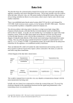
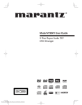
•PT2500(g).qx 10/23/96 7:36 AM Page 16 Harman Kardon PT2500 A/VSurround Tuner Controller Volume Tuning 1 2 3 4 5 DIRECT Scan DOLBY 3-CH THEATER 6 7 8 9 0 0-30 STADIUM PHANTOM MEMORY AM PRESET MHz DELAY Tuned TIME FMST SLEEP KHz FM AM TAPE2MON AUTO VCR1REC FM Loudness MS MIN FM Mode SOURCE VDP Auto/Man VCR2 Memory Off Power CENTER MODE NORM WIDE VCR 2 Pro-Logic Stadium Test Tape 1 VCR 1 VCR 2 Tuner CD Bass Treble Balance VCR 2 Direct Delay 3 Ch Theater Center Tape2Mon Rec VDP TV/Aux Phono Sel Owner’s Manual PT2500 rev (G) 10/23/96 •PT2500(g).qx 10/23/96 7:36 AM Page 1 Table of Contents Introduction & Safety Information. . . . . . . . . . . . . . . . . 1 Features . . . . . . . . . . . . . . . . . . . . . . . . . . . . . . . . 1 Unpacking and Installation . . . . . . . . . . . . . . . . 3 Using this manual . . . . . . . . . . . . . . . . . . . . . . . 3 Front Panel Controls . . . . . . . . . . . . . . . . . . . . . . . . . . . . 4 Rear Panel Connections . . . . . . . . . . . . . . . . . . . . . . . . . 5 System Remote Control. . . . . . . . . . . . . . . . . . . . . . . . . . 6 Installation and Configuration . . . . . . . . . . . . . . . . 7–10 Operation. . . . . . . . . . . . . . . . . . . . . . . . . . . . . . . . . 11–12 Troubleshooting . . . . . . . . . . . . . . . . . . . . . . . . . . . . . . 13 Technical Specifications . . . . . . . . . . . . . . . . . Back Cover 80 Crossways Park West Woodbury, NY 11797 ©1996 Harman Kardon, Incorporated PT2500 rev (G) 10/23/96 •PT2500(g).qx 10/23/96 7:36 AM Page 2 Introduction and Safety Information 1 Congratulations! With the purchase of a Harman Kardon PT2500 you are about to begin many years of listening enjoyment. The PT2500 has been custom designed to provide all the excitement and detail of movie soundtracks and every subtle nuance of musical selections. While complex processing systems are hard at work within the PT2500, hookup and operation are simple. Color keyed connections, a comprehensive remote control and on screen menus make the PT2500 easy to use. To obtain the maximum enjoyment from your new receiver we urge you to take a few minutes to read through this manual. This will ensure that connections to speakers, source playback units and other external devices are made properly. A few minutes spent learning the functions of the various controls will enable you to take advantage of all the power the PT2500 is able to deliver. If you have any questions about this product, its installation or operation, please contact your dealer. They are your best local source of local information. You may also contact Harman Kardon directly via the Internet at http://www.harmankardon.com. Description and Features The PT2500 is a full featured A/V surround tuner controller, incorporating a wide variety of listening options. Through the use of an Analog Devices decoder, surround encoded programs are played back with stunning accuracy, while the direct mode enables stereo recordings to be played back in their purest form. The open architecture of a surround tuner controller allows for easy expansion to full discrete surround decoding with external adapters. *Trademarks of Dolby Laboratories PT2500 rev (G) 10/23/96 Five audio inputs, three audio/video inputs and the PT2500’s 30 preset tuner enable it to serve as the control center for a complete audio/video system. A system remote control operates the PT2500 and compatible Harman Kardon source equipment, while an on board trigger jack provides control capability to automatically turn on the companion PA5800 amplifier. Features ■ Analog Devices decoding circuit for precise surround decoding ■ Dolby* ProLogic*, Dolby 3 Stereo, Theater and Stadium surround modes ■ Direct Mode for pure stereo playback ■ System remote control ■ Remote Trigger Control for PA5800 create a safety and fire hazard, and may damage the amplifier. Important Safety Information Handle the AC Power Cord Gently When disconnecting the power cord from an AC outlet, always pull the plug, never pull the cord. If you do not intend to use the amplifier for any considerable length of time, disconnect the plug from the AC outlet. Verify Line Voltage Before Use Your PT2500 has been designed for use in North America with 120 volt AC current. Connection to a line voltage other than that for which it is intended can If you have any questions about the voltage requirements for your specific model, or about the line voltage in your area, contact your dealer before plugging the unit into a wall outlet. Do Not Use Extension Cords To avoid safety hazards, use only the power cord supplied with your unit. If a replacement cord is used, make certain that it is of similar gauge. We do not recommend that extension cords be used with this product. As with all electrical devices, do not run power cords under rugs or carpets or place heavy objects on them. Damaged power cords should be replaced immediately with cords meeting factory specifications. C AUTION RISK OF ELECTRICAL SHOCK DO NOT OPEN CAUTION: TO REDUCE THE RISK OF ELECTRIC SHOCK, DO NOT REMOVE COVER (OR BACK). NO USER-SERVICEABLE PARTS INSIDE. REFER SERVICING TO QUALIFIED SERVICE PERSONNEL. The lightning flash with arrowhead symbol, within an equilateral triangle, is intended to alert the user to the presence of uninsulated “dangerous voltage” within the product’s enclosure that may be of sufficient magnitude to constitute a risk of electric shock to persons. The exclamation point within an equilateral triangle is intended to alert the user to the presence of important operating and maintenance (servicing) instructions in the literature accompanying the appliance. WARNING: TO REDUCE THE RISK OF FIRE OR ELECTRIC SHOCK, DO NOT EXPOSE THIS APPLIANCE TO RAIN OR MOISTURE. CAUTION: TO PREVENT ELECTRIC SHOCK, DO NOT REMOVE THE GROUNDING PLUG ON THE POWER CORD, OR USE ANY PLUG OR EXTENSION CORD THAT DOES NOT HAVE A GROUNDING PLUG PROVIDED. MAKE CERTAIN THAT THE AC OUTLET IS PROPERLY GROUNDED. DO NOT USE AN ADAPTER PLUG WITH THIS PRODUCT. •PT2500(g).qx 10/23/96 7:36 AM Page 3 Introduction and Safety Information 2 Do Not Open The Cabinet There are no user serviceable components inside this product. Opening the cabinet may present a shock hazard, and any modification to the product will void your guarantee. If water or any metal object such as a paper clip, wire or a staple accidentally falls inside the unit, disconnect it from the AC power source immediately, and consult an authorized service center. CATV or Antenna Grounding If an outside antenna or cable system is connected to this product, be certain that it is grounded so as to provide some protection against voltage surges and static charges. Section 810-B of the National Electrical Code, ANSI/NFPA No. 70-1996, provides information with respect to proper grounding of the mast and supporting structure, grounding of the lead-in wire to an antenna discharge unit, size of grounding conductors, location of antenna discharge unit, connection to grounding electrodes and requirements of the grounding electrode. NOTE TO CATV SYSTEM INSTALLER: This reminder is provided to call the CATV (Cable TV) system installer’s attention to article 820-40 of the NEC that provides guidelines for proper grounding and, in particular, specifies that the cable ground shall be connected to the grounding system of the building, as close to the point of cable entry as possible. Installation Location ■ To assure proper operation, and to avoid the potential for safety hazards, place the unit on a firm and level surface. When placing the unit on a shelf, be certain that the shelf and any mounting hardware can support the weight of the product. PT2500 rev (G) 10/23/96 ■ Make certain that proper space is provided both above and below the unit for ventilation. If this product will be installed in a cabinet or other enclosed area, make certain that there is sufficient air movement within the cabinet. Under some circumstances a fan may be required. ■ Do not place the unit directly on a carpeted surface. ■ Avoid installation in extremely hot or cold locations, or an area that is exposed to direct sunlight or heating equipment. ■ Avoid moist or humid locations. ■ Do not obstruct the ventilation slots on the top of the unit, or place objects directly over them. Cleaning When the unit gets dirty, wipe it with a clean, soft dry cloth. If necessary, wipe it with a soft cloth dampened with mild soapy water, then a fresh cloth with clean water. Wipe dry immediately with a dry cloth. NEVER use benzene, thinner, alcohol or any other volatile cleaning agent. Do not use abrasive cleaners, as they may damage the finish of metal parts. Avoid spraying insecticide near the unit. Moving The Unit Before moving the unit, be certain to disconnect any interconnection cords with other components, and make certain that you disconnect the unit from the AC outlet. Important information for the user Note: This equipment has been tested and found to comply within the limits for a Class B digital device, pursuant to Part 15 of the FCC Rules. The limits are designed to provide reasonable protection against harmful interference in a residential installation. This equipment generates, uses and can radiate radio frequency energy and, if not installed and used in accordance with the instructions, may cause harmful interference to radio communication. However, there is no guarantee that harmful interference will not occur in a particular installation. If this equipment does cause harmful interference to radio or television reception, which can be determined by tuning the equipment off and on, the user is encouraged to try to correct the interference by one or more of the following measures: ■ Reorient or relocate the receiving antenna. ■ Increase the separation between the equipment and receiver. ■ Connect the equipment into an outlet on a circuit different from that to which the receiver is connected. ■ Consult the dealer or an experienced radio/TV technician for help. This device complies with Part 15 of the FCC Rules. Operation is subject to the following two conditions: (1) this device may not cause harmful interference, and (2) this device must accept interference received, including interference that may cause undesired operation. Note: Changes or modifications may cause this unit to fail to comply with Part 15 of the FCC Rules and may void the user’s authority to operate the equipment. •PT2500(g).qx 10/23/96 7:36 AM Page 4 Introduction and Safety Information 3 Unpacking and Installation The carton and shipping materials used to protect your new PT2500 during shipment were specially designed to cushion it from shock and vibration. We suggest that you save the carton and packing materials for use in shipping if you move or should the unit ever need repair. To minimize the size of the carton in storage, you may wish to flatten it. This is done by carefully removing any staples that attach the carton flaps to one another, and then slitting the tape covering the seams. Fold the carton down to a more two dimensional appearance. Packing materials that cannot be collapsed should be saved along with the carton in a plastic bag. If you do not wish to save the packaging materials, please note that the carton and other sections of the shipping protection are recyclable. Please respect the environment and discard those materials at a local recycling center. PT2500 rev (G) 10/23/96 When positioning your PT2500 in its final location, make certain that any shelf or stand is capable of supporting it’s weight, and that there is adequate ventilation on all sides, as well as on the top and bottom. Do not place CDs, record jackets, owner’s manuals, or other paper on top of, or beneath the unit. This will block air flow, causing degraded performance and a possible fire hazard. If the unit is to be enclosed in a cabinet or rack, make certain that there is adequate air circulation, with a means provided for hot air to exit, and for cool air to be brought in. Using this Manual For easy identification of the inputs, outputs and controls on the PT2500, a separate reference card accompanies this manual. Printed on that card are diagrams of the front and rear panels and the remote control. Refer to that card as needed to make certain that connections are being made properly. The following conventions are used throughout this manual when referring to the diagrams on the reference card: 1: A number within a square references a front panel control. ¡ : A number within a circle references a connection point on the rear panel. a : A number within an oval references a button on the remote control. Example : Bold type will be used to indicate a front or rear panel control. It will typically be followed with a reference letter or number to the specific control being described. EXAMPLE : OCR type indicates a message that is visible through the display window. •PT2500(g).qx 10/23/96 7:36 AM Page 5 Front Panel Controls 4 Using the Reference Card supplied with this manual, familiarize yourself with each of the controls on the front panel of the PT2500. This section of the Manual will also serve as a quick reference to the operation of any of these controls. 1 Power Switch: Press this button to turn the PT2500 on or off. In order to use the power button on the remote this power switch must be pressed once and left in the “standby” mode. Note that a green indicator around the switch will illuminate when the unit is on, and an orange ”standby” indicator will illuminate when the unit has been turned off using the remote control. 2 VCR2 Selector: Press this button to select the front panel VCR2 inputs rather than the rear panel inputs. 3 Direct Input Selector: Press this button to select direct input to the preamp circuits, bypassing all tone controls and surround processing. When this feature is activated, the DIRECT indicator illuminates within the information display. 4 Delay Time Adjust: Press this button to adjust the delay time between the front and rear channels. 5 Surround Off: Press this button to select conventional two channel stereo reproduction and to cancel surround processing. 6 Surround Mode Selectors: Press one of these buttons to select a surround processing mode. 7 Center Channel Mode Selector: Press this button to change the center channel mode. 8 Test Mode Selector: Press this button to place the unit in the Test mode for adjustment of system output levels. 9 Tape 2 Monitor: Press this button to monitor the output of the tape deck connected to the Tape 2 Inputs. For normal operation this control should be in the off position. ) Input Selectors: Press one of these buttons to select an input source. PT2500 rev (G) 10/23/96 ! Bass Control: Turn this control to adjust the low frequency output of the left/right channels by as much as ±10dB. Set this control to a suitable position for your taste and room acoustics. @ Treble Control: Turn this control to adjust the high frequency output of the left/right channels by as much as ±10dB. Set this control to a suitable position for your taste and room acoustics. # Balance Control: Turn this control to change the relative volume for the front left/right channels. NOTE: For normal operation of the surround modes this control should be at the midpoint, or “12 O’clock” position. $ VCR2 Inputs: This alternate set of VCR2 Inputs may be used for the connection of a camcorder or video game. Select this input by pressing the VCR2 button 2 on the front panel. % Loudness Button: Press this button when listening at low levels to activate special circuits that compensate for the response of the human ear at lower volumes. In the off position the unit will provide flat frequency response. ^ Volume Control: Rotate this control to raise or lower the volume. Note that this is a motorized control, and when the volume is changed using the remote control n it will move in response to remote commands. & Mute/Volume Indicator: In normal operation this green LED provides a relative indication of the unit’s volume level. When the PT2500 is in the MUTE mode, this indicator flashes to remind you that output to the speakers has momentarily been silenced. * Auto/Man Selector: Press this button to select AUTO or MANUAL tuning. In the AUTO mode the tuner will stop only at stations with a strong signal. In the MANUAL mode the tuner will step in 50 kHz increments for FM and 10 kHz increments for AM. ( AM/FM Selector: Press this button to select AM or FM stations. Ó Up/Down Tuning Button: Press the left side ¤ of the button to tune lower frequency stations and the right side ⁄ of the button to tune higher frequency stations. When a station with a strong frequency is tuned, the T U N E D indicator will illuminate in the Information Display . Ô FM Mode: Press this button to select the stereo or mono mode for FM tuning. In the STEREO mode an F M S T indicator will illuminate in the information display, and stereo reception will be provided when stations are transmitting stereo signals. In the MONO mode the left and right signals from stereo broadcasts will be mixed together and reproduced through all channels. Select the MONO mode fro better reception of weak signals. Information Display: The indicators in this display illuminate to provide visual display of the unit’s operation. Ò Remote Sensor: This sensor receives the signals from the remote control to operate the unit. Do not block this area. Ú Tuner Memory Button: Press this button to store an AM or FM frequency in the unit’s memory. The MEMORY indicator will flash in the display to remind you to choose a numeric location using Numeric Buttons on the front panel or remote (Ù d). Press this button a second time to complete the memorization process. Storing a station in a memory location that has already been used will overwrite the existing data. NOTE: The preset memories are protected from power loss for two weeks. If the unit is unplugged for more than two weeks all stored frequencies will be erased. Û Preset Scan Button: Press this button to scan the stations entered in the unit’s memory. When the desired station is reached, press the button again to stop the scan. Ù Numeric Buttons: Use these buttons to enter or recall stations from the tuner memory. •PT2500(g).qx 10/23/96 7:36 AM Page 6 Rear Panel Connections 5 Using the Reference Card supplied with this manual, use this section as a quick guide to the connections required to install the PT2500. For complete installation and set up instructions, see pages 7-10. ¡ Phono Input: Connect the output of a turntable or tone arm to these jacks. ™ System Ground Terminal: To reduce hum and noise, connect the ground lead from your turntable or tone arm to this terminal. £ Aux Input: Connect the outputs of any audio source to these jacks. ¢ CD Input: Connect the outputs of a CD player or external D/A converter to these jacks. ∞ Tape 1 Input: Connect the PLAY/OUT jacks of an audio tape recorder to these jacks. § Tape 1 Output: Connect the RECORD/INPUT jacks of an audio tape recorder to these jacks. ¶ Tape 2 Input: Connect the PLAY/OUT jacks of a second audio tape recorder to these jacks. • Tape 2 Monitor Output: Connect the RECORD/INPUT jacks of a second audio tape recorder to these jacks. ª VCR1 A/V Inputs: Connect the audio and video PLAY/OUT jacks of a VCR to these jacks. ‚ VCR1 A/V Outputs: Connect the audio and video record RECORD/IN jacks of a VCR to these jacks. ⁄ VCR2 A/V Inputs: Connect the audio and video PLAY/OUT jacks of a second VCR, or another A/V source such as a satellite receiver to these jacks. PT2500 rev (G) 10/23/96 ¤ VDP A/V Inputs: Connect the audio and video outputs of a laser disc or DVD player to these jacks. ‹ Video Monitor Outputs: Connect these jacks to the video input of a TV or video projector. › Remote Amplifier Trigger: Using the accessory cable supplied with the PT2500, connect this jack to compatible products such as the PA5800 for automatic turn on/off operation. fi AC Power Cord: Connect this plug to an unswitched, wall mounted AC outlet. fl Unswitched Accessory AC Power Outlet: This outlet provides AC power that may used with any AC device up to 100 watts. The power will remain on at this outlet regardless of whether the PT2500 is on or off. ‡ Switched Accessory AC Power Outlet: This outlet provides AC power to connected products only when the PT2500 is turned on. Note that the total current draw of the products may not exceed 100 watts. ° Remote Control Extension Output: This jack may be connected to other compatible Harman Kardon products so that they will receive infrared commands captured by the PT2500’s remote sensor. · Remote Control Extension Input: If the PT2500’s front panel IR sensor is blocked due to cabinet doors or other obstructions, an external IR sensor may be used. Connect the output of the sensor to this jack. a Surround Channel Outputs: Connect these jacks to the surround channel inputs of a power amplifier or digital audio processor with pass through capability. b Center Channel Outputs: Connect the output of one of these jacks to the center channel input of a power amplifier or digital audio processor with pass through capability. NOTE: In most applications only one center channel connection will be required. The output of both jacks is identical, and either jack may be used for system connections. c Front Channel Outputs: Connect these jacks to the front left/right channel inputs of a power amplifier or digital audio processor with pass through capability. d Subwoofer Outputs: Connect these jacks to the line level input of a powered subwoofer, or to the inputs of a subwoofer amplifier. NOTE: This output is a full range left/right signal. For proper operation BOTH jacks must be connected to the left/right inputs of a powered subwoofer, or a “Y” cable must be used to connect the two outputs together if a single input mono subwoofer is used. WARNING: Since this is a full range output, the signal must be sent through a crossover or low pass filter before being used with a passive subwoofer or other speaker that does not contain a built in crossover. e AM Antenna Input: Connect the AM loop antenna supplied with the PT2500 to these terminals. An external AM antenna may also be connected here. f FM Antenna Input: Connect an FM antenna to these terminals. Note that a 300 ohm to 75 ohm adapter is required for connections from twin lead dipole antennas. •PT2500(g).qx 10/23/96 7:36 AM Page 7 System Remote Control 6 Using the Reference Card supplied with this manual, familiarize yourself with each of the controls on the PT2500’s infrared remote control. This section of the manual will also serve as a quick reference to the operation of any of these controls. f Input Select Buttons: Press one of these buttons to choose an input source. a Transmitter Window: An infrared beam is transmitted from this window when you press any button on the remote. For the remote to function properly always point this window toward the remote sensor on the PT2500 and do not obstruct this window. g Delay Time Adjust: Press this button to adjust the amount of delay between the sounds heard from the front and surround speakers. This function is only available in the Dolby ProLogic, Theater and Stadium modes. Note: Automatic Power On: When you press any Input Select Button while the unit is in the Standby Mode, the system will automatically be turned on. h Surround Mode Selectors: Press one of these buttons to choose a surround processing mode. Press the OFF button to cancel the surround processing for conventional stereo reproduction. i Center Level Up/Down Buttons: These buttons adjust the center channel volume relative to that of the other speakers. They operate only in the Dolby ProLogic and Dolby 3 Stereo modes. Remote Control Operation Range b Power Button: Press this button to turn the PT2500 on or off. NOTE: In order for this button to work, the PT2500 must first be placed in the standby mode by pressing the front panel Power switch 1 until it is engaged and the ring surrounding the switch turns amber. c Up/Down Tuning Buttons: Press these buttons to manually tune higher or lower frequency stations. d Numeric Buttons: Press these buttons to select one of the stations stored in the unit’s memory. e CD Function Controls: These buttons will control the functions of a compatible Harman Kardon CD player or multi disc changer. PT2500 rev (G) 10/23/96 j Rear Level Up/Down Buttons: These buttons adjust the volume of the rear (Surround) channels relative to that of the other speakers. They operate only in the Dolby ProLogic, Theater and Stadium modes. k Display Dim: Press this button to dim the brightness of the front panel display. A second press turns that display off completely and a third press returns the displays to their normal brightness level. l Sleep Timer Button: Press this button to activate the sleep timer. Each press increases the amount of time before the unit will turn off, in the following sequence: 10 min 20 min 30 min 60 min 90 min OFF m Mute Button: Press this button to momentarily silence the speakers. Note that the Mute/Volume Indicator & will flash to remind you that the Mute function is engaged. Press the button again to return to the previously selected listening level. n Master Volume Control: Press this button to raise or lower the overall system volume to all speakers. o Center Mode Select: Press this button to select the center channel mode. Each press of the button changes the mode in the following sequence: Normal ‡ Wide‡ Phantom p Test Mode Select: Press this button to have a test signal noise appear in sequence through the left, center, right and surround speakers so that relative volume may be adjusted. q Cassette Deck Controls: These buttons control the functions of compatible Harman Kardon cassette decks. r Preset Scan Button: Press this button to scan the stations entered in the unit’s memory. When the desired station is reached, press the button again to stop the scan. s Battery Compartment: Install two “AA” batteries as shown to power the remote control. Slide the cover on the battery compartment as shown to remove. Insert the batteries being certain to observe proper polarity. •PT2500(g).qx 10/23/96 7:36 AM Page 8 Installation & Configuration 7 Your new Harman Kardon receiver is designed to provide the best reproduction from both movies and musical programs. To assure that the unit operates to its fullest capability, it is important that you spend a few minutes to properly install and configure all of the elements in your new system. Some, or all of the following steps will apply to your system, depending on the equipment in use. If you have any questions concerning the installation of this product consult your local dealer, or contact the Harman Kardon web site at http://www.harmankardon.com. System Component Connections IMPORTANT SAFETY NOTE: Many products feature automatic turn on circuitry which may accidentally be activated when making connections. For your safety and to prevent damage to speakers, amplifiers and other components we strongly recommend that all equipment power be turned off, or that AC power cords be unplugged when any system connections are made or changed. Using high quality interconnect cables, connect all source components to the appropriate input jacks on the rear panel. When connecting audio recorders and VCRs it is important to make certain that the PLAY/OUT jacks on the recorders are connected to the PLAY jacks on the PT2500, and that the RECORD/IN jacks of the recorders are connected to the REC jacks on the PT2500. If the phono input is used, connect the small ground wire connection furnished on most turntables to the System Ground Terminal ™ on the rear panel. This will greatly reduce system noise and hum. Assemble the supplied AM loop antenna as shown below and connect it to the AM ANTENNA Terminals e. AM LOOP ANTENNA SETTING LEG Stand and place it on a shelf, or hang it on a wall. It may be necessary to rotate the antenna or change its position to achieve the best AM reception. Connect an FM antenna to the FM Antenna Terminals. A 300 ohm to 75 ohm adapter may be required for some antennae. If a PA5800 or other compatible amplifier will be used, connect the supplied accessory cable to the Remote Amplifier Trigger Jack › on the PT2500. Connect the other end to the appropriate jack on your amplifier. Consult the amplifier manual for further instructions. IMPORTANT NOTE: Do not connect amplifier trigger cables to the “IR Remote Control” jacks on this or any other equipment. If you are using the PT2500 to switch video inputs, connect either MONITOR output ‹ to a video input on your TV or projector. The rear panel accessory outlets on the PT2500 may be used to power low current devices such as CD payers or tape decks. The SWITCHED Accessory AC Power Outlets ‡ are activated only when the PT2500 is turned on. The UNSWITCHED Accessory AC Power Outlets fl may be used with VCRs, as the power to these outlets is live as long as the PT2500 remains connected to an AC power source. CAUTION: The total power load for all products connected to the accessory outlets must not exceed 100 watts. Do not use them for high current devices such as power amplifiers. If the PT2500’s front panel remote sensor Ò is blocked by cabinet doors you may still operate the unit via remote control with the use of an optional external remote sensor. Connect the output of the sensor to the rear panel REMOTE CONTROL Extension Input ·. This jack may also be used as the IR input from compatible multiroom control systems. The sensor may be looped to other components by connecting the REMOTE CONTROL Extension Output ° to the IR remote input jack of other compatible components. Amplifier Connections Since the PT2500 is a tuner/preamplifier, it does not include any on board power amplifiers. The final step in the installation process is to connect the unit to the amplifiers for each channel. Using high quality audio interconnect cables, connect the FRONT, CENTER and SURROUND Channel Outputs cba to the appropriate input jacks of a power amplifier. PT2500 rev (G) 10/23/96 •PT2500(g).qx 10/23/96 7:36 AM Page 9 Installation & Configuration 8 Subwoofer connections are made using the SUBWOOFER Outputs d. When using a powered subwoofer, connect BOTH the left and right output subwoofer outputs to the respective left and right line level inputs on your subwoofer. As the PT2500 subwoofer outputs are full range, it will be necessary to adjust the crossover frequency to your requirements on the subwoofer’s control panel. Consult the subwoofer instructions or consult your dealer for additional information. When using a single subwoofer and a separate mono power amplifier the PT2500 subwoofer outputs must be combined using an optional “Y” adapter. If there is no crossover in the subwoofer an optional, external low pass filter or crossover system must also be used. When using the PT2500 with an external 5.1 digital audio decoder such as the Harman Kardon ADP303, connect all Channel Outputs abc to the decoder’s inputs. Use an optional “Y” adapter to combine the subwoofer outputs and connect the “Y” adapter to the decoder’s subwoofer input. The outputs of the digital audio decoder should then be connected to your power amplifiers. Speaker Selection and Placement Depending on the type of center channel speaker in use and your viewing device, place the center speaker directly above or below your TV . PT2500 rev (G) 10/23/96 Once the center channel speaker is installed, position the left and right front speakers so that they are as far away from one another as the center channel speaker is from the preferred listening position. Ideally, the front channel speakers should be placed so that their tweeters are no more than 24″ off center from the tweeter in the center channel speaker. Depending on the specifics of your room acoustics and the type of speakers in use, imaging may be improved by moving the front left and right speakers slightly forward of the center channel speaker. If possible, adjust all front loudspeakers so that they are aimed at ear height when you are seated in the listening position. Using these guidelines, you may find that it takes some experimentation to find the correct location for the front speakers in your particular installation. Don’t be afraid to move things around until the system sounds correct. Optimize speaker locations so that pans across the front of the room sound smooth, and that sounds from all speakers appear to arrive at the listening position at the same time without delay from the center speaker as opposed to the left and right speakers. Surround speakers should be placed on the side walls of the room, at or slightly behind the listening position. The center of the speaker should face into the room with the speaker drivers pointing towards the front and rear of the room. The speakers should be located so that the bottom of the cabinet is at least 24″ higher than the listeners’ ears when in the desired area. Center Front Speaker No more than 24" Left Front Speaker Right Front Speaker A) Front Channel Speaker Installation with Direct View TV Sets or Rear Screen Projectors TV or Projection Screen Left Front Speaker Center Front Speaker Right Front Speaker No more than 6 feet when rear-mounted speakers are used Although there are two outputs for the center channel, only one connection is typically required. As the two outputs are identical, either one may be used and the other left open. Optional Rear Wall Mounting The distance between the left and right speakers should be equal to the distance from the seating position to the viewing screen. You may also experiment with placing the left and right speakers slightly forward of the center speaker. At least 6 inches from ceiling At least 2 feet •PT2500(g).qx 10/23/96 7:36 AM Page 10 Installation & Configuration 9 If side wall mounting is not practical, the speakers may be placed on a rear wall, behind the listening position. Again, they should be located so that the bottom of the cabinet is at least 24″ higher than the listeners’ ears. The speakers should be no more than 6 feet behind the rear of the seating area. Subwoofers produce non-directional sound, so they may be placed almost anywhere in a room. Subwoofer placement is highly influenced by room size and shape, and the type of subwoofer used. Follow the instructions of the subwoofer’s manufacturer, or experiment with the best location for a subwoofer in your listening room. Output Level Calibration For proper operation in the surround modes it is important that the level from all channels be as close to one another as possible. A small amount of time spent to properly calibrate the PT2500’s output levels will enable the unit to deliver all the performance it is capable of within the specific environment of your listening room. IMPORTANT NOTE: People are often confused about the operation of the surround channels. While some assume that sound should always be coming from each speaker, most of the time there will be little or no sound in the rear channels. This is because they are only used when a movie director or sound mixer specifically places sound there to create an effect or pull you into the action. When the output levels have been properly set it is normal for the rear speakers to operate only occasionally. Artificially increasing the volume to the rear speakers will destroy the illusion of an enveloping surround field that duplicates the way you hear sound in a movie theater or concert hall. PT2500 rev (G) 10/23/96 To calibrate your system, follow these steps: 1. Turn on the PT2500 and the companion power amplifier. 2. Select the Dolby ProLogic mode using the Surround Mode 6 button on the front panel. 3. Place the front panel Balance # control at its midpoint position, so that the indicator is pointing straight up in the 12 o’clock position. If the Balance control is normally in another position to compensate for speaker placement relative to your preferred listening position, leave it in that spot. 4. Sit in the location that you will normally occupy when using your PT2500. 5. Press the Test Tone p8 button on the remote or front panel and note that a test noise signal will circulate between the channels. • While the test noise circulates among the channels the word TEST and the channel name will appear in the front panel information display window. As the names change you should first listen to the location of the tone and verify that it matches the name displayed in the display. If the display indicates a different location than the speaker the test noise is coming from you should turn off the unit and verify that the connections to the amplifier speakers are made to the correct terminals on the rear panel. 6. As the test signal circulates among the channels, use the Center Level Up/Down o and Rear Level Up/Down j buttons on the remote to adjust the level so that the volume from all channels sounds equal. 7. Press the Test Tone 8 button again to turn the test signal off. Your system is now properly calibrated and further volume adjustment should be made using the Master Volume n buttons on the remote or the front panel Volume Control. ^ Once the system is calibrated no other adjustments are necessary. Delay Setting Delay time adjustment enables you to adjust the timing between signals at the front and surround channels. The factory setting is appropriate for most rooms, but in some instances the use of an abundance of hard (reflective) room surfaces such as windows and wood floors, or soft (absorbent) surfaces such as thick carpeting, acoustical tiles and some furnishings may create an unpleasant effect. These surfaces, in conjunction with the size of the room, the height of the ceiling and other design aspects may cause the arrival of surround channel sounds to become disconnected from rear channel sounds. To adjust delay time it is necessary to select the ProLogic, Theater or Stadium modes using the Surround Mode Selector buttons on the front panel or remote h6 . Press the Delay Adjust button 4 on the front panel to adjust the delay time as observed in the Information Display according to personal preference or the following formula: 1. Measure the distance from the listening/viewing position to the front speakers. 2. Measure the distance from the listening/viewing position to the surround speakers. •PT2500(g).qx 10/23/96 7:36 AM Page 11 Installation & Configuration 10 3. Subtract the distance to the rear/surround speakers from the distance to the front speakers and add 15. The resulting number is the ideal delay time for your room. For example, if the front speakers are 10 feet away and the surround speakers are 5 feet away, the formula will be “10-5+15=20”. Thus, the correct delay time in this room would be 20 ms. Note that the delay time for the Dolby ProLogic Mode is adjusted in 2 ms increments from 16 ms. to 30 ms. The delay setting for the Theater and Stadium modes is adjusted in 8 ms increments from 8ms to 96 ms. Center Channel Mode The PT2500 permits you to tailor the center channel output to match the type of speakers used in your home theater. Press the Center Mode button o7 on the front panel or remote to select one of the following. The center channel mode is shown by indicators in the front panel display window. CENTER FRONT(left) REAR(left) FRONT(right) REAR(right) Wide Mode: Select this mode if your center channel speaker is a traditional full range loudspeaker. FRONT(left) REAR(left) FRONT(right) REAR(right) CENTER FRONT(left) REAR(left) FRONT(right) REAR(right) Normal Mode: Select this mode if your center channel is small and has limited bass response. Most specialized center channel speakers fall into this category. PT2500 rev (G) 10/23/96 Phantom Mode: Select this mode if a center channel speaker is not used. The PT2500 will create a “phantom” center channel using the outputs of the left and right speakers. Note that the Phantom mode is not available when Dolby 3 Stereo is selected as a surround mode. •PT2500(g).qx 10/23/96 7:36 AM Page 12 Operation 11 4. Adjust the Center Channel Mode 7o and/or Delay Time 4g if a change is required from the setting established during installation. names described above, select the ProLogic mode using the front panel or remote Surround Mode Selectors 6h. • To use the remote for power on/off it is necessary to turn the unit on from the front panel switch and to leave the switch in the “on” position. The PT2500 may then be turned off using the Power button b on the remote. When the remote is used to turn the unit “off” it is actually placing the system in a standby mode, as indicated by the amber color of the power switch ring. 5. Adjust the volume to a comfortable level using the front panel Volume Control or remote Volume Up/Down buttons ^n . • If you will be away from home for an extended period of time it is always a good idea to completely turn the unit off using the front panel Power button 1. • To remove the tone controls from the circuit, press the Direct button 3. If a center channel speaker is used along with front left/right speakers, but no surround speakers are used, choose the Dolby 3 Stereo mode6h. This combines the surround signal into the front left and right channels to create a greater feeling of presence and a more expansive sound field than with conventional stereo signals. Center channel dialog information will continue to be heard through its proper place at center screen. OPERATION 1. Press the Power button 1 on the front panel to turn the unit on. 2. Select the desired program source using the Input Selector Switches 9)f on the front panel or remote. • To use a camcorder or video game which is connected to the front panel VCR2 input, press the VCR2 Sel button 2. • When the selected input is VCR1, VCR2 or VDP the video signal for that input will be routed to the MONITOR output jacks ‹ and will be viewable on a TV monitor connected to the PT2500. Make certain that your TV set is set to the proper “VIDEO” input to view the signal. 3. Choose a surround mode using the Surround Mode Selector 6h buttons on the front panel or remote. To listen to traditional two channel stereo press the Surround Off button 5h. PT2500 rev (G) 10/23/96 • To temporarily silence the system press the Mute button m on the remote. 6. Adjust the Bass and Treble controls !@ to suit your listening taste. • At lower volume levels you may wish to engage the Loudness button % to boost low and high frequency sounds to compensate for response of the human ear at low listing levels (known as the Fletcher-Munson hearing curve). Surround Mode Options Surround sound processing enables four separate audio signals to be transmitted within the left and right channels of a videocassette, radio or TV broadcast, or video disc. Through a process known as matrix encoding a separate center channel signal for dialog and a surround channel for effects are encoded into the stereo signal. When you see the Dolby Surround™, Dolby Stereo™, DTS Stereo™ or other similar logos on a movie or broadcast this indicates that the program has surround information. When the program you are listening to has encoded surround information, as shown by one of the logos or brand When listening to conventional stereo recordings or programs, those with separate left and right channels but no intentionally recorded surround information, you may wish to experiment with the surround modes to see which produces the effect you prefer. Stereo recordings often contain sufficient natural phase differences so that the ProLogic or Dolby 3 Stereo Modes are enjoyable, despite the lack of true surround information. Stereo recordings may also sound more expansive in either the Theater or Stadium modes. Selecting these modes 6h uses the front left and right speakers for normal stereo, while the surround speakers are fed a reverberated sound. In order to provide for a wider variety of sound field effects, the surround channel delay available in the Theater and Stadium modes is substantially greater than that in Dolby ProLogic. NOTE: The center channel speaker is not operational in the Theater or Stadium modes. •PT2500(g).qx 10/23/96 7:36 AM Page 13 Operation 12 Tuner Operation The PT2500’s built in tuner is capable of tuning AM, FM or FM Stereo broadcast stations. Stations may be tuned manually, automatically or via presets. Manual Tuning 1. Press the Tuner button )f to select the tuner as an input. 2. Select the AM or FM band using the front panel AM/FM selector (. 3. Press the Tuning ⁄¤ Óc button to until the desired station is tuned. Holding the button down will cause a rapid advance through the frequency band, tapping it lightly will advance through bands one increment at a time. The TUNED indicator will illuminate when a station is received with sufficient strength for quality reception. 4. Press the FM Mode Ô button to switch between mono and stereo reception. When a station’s signal is weak, press the button until the FMST indicator in the information display goes out. This will switch the tuner to mono, but it may enable clearer reception. Auto Tuning 1. Press the Tuner button )f to select the tuner as an input. 2. Select the AM or FM band using the front panel AM/FM selector (. 3. Press the Auto/Man * button. 4. Press the Tuning Óc button once and tuning will start in the direction indicated. The tuner will stop at the first station with sufficient signal strength. PT2500 rev (G) 10/23/96 Preset Tuning Up to 30 stations may be stored in the receiver’s memory for easy recall using the front panel controls or the remote. To enter a station to the memory, first tune to the station using the steps outlined above in the Manual Tuning section. Then: 1. Press the Memory Ú button on the front panel. Note that the MEM indicator in the Information Display window will illuminate and flash. 2. Within five seconds, press the Numeric Buttons Ùd corresponding to the memory location where you wish to store this station’s frequency. • To enter a station to memory location “30” press only the 0 button. 3. Repeat the process after tuning to any additional stations to be preset. Recalling Preset Stations To select a station previously entered into the preset memory press the Numeric Buttons Ùd on the front panel or the remote corresponding to the desired station’s location. To select the station in location “30”, press the 0 button only. • When you select a station using this method the unit will automatically switch to the tuner as its input. Preset Station Scan To automatically scan through the stations entered in the preset memory, press the P•Scan r button on the remote. The tuner will automatically begin to search through the list of stations, stopping for four seconds at each one. Press the P•Scan button again to stop the scan at your desired station. Sleep Timer The PT2500 may be placed in a “Sleep Mode” mode by pressing the Sleep Timer l button on the remote. Each press of the button increases the time until the unit shuts off in the following increments: 10 min 20 min 30 min 60 min 90 min OFF The sleep time will be displayed at the right side of the Information Display while the timer is being programmed. Once the amount of time entered has elapsed, the PT2500 will automatically go into the Standby mode, shutting off all functions as well as the remote amp trigger and the switched outlets. Tape Recording In normal operation, the audio or video source selected for listening through the PT2500 is sent to the record outputs. This means means that any program you are watching or listening to may be recorded simply by placing machines connected to the outputs for TAPE 1 § or VCR1 ‚ in the record mode. To dub an audio tape place the blank tape in the machine connected to Tape 2 and put it in the record mode. Place the program tape in the machine connected to Tape 1 and put it in the play mode. Select Tape 2 Mon as the input source 9f to monitor the playback of the dub if the recorder has a three head system. •PT2500(g).qx 10/23/96 7:36 AM Page 14 Troubleshooting 13 This unit is designed for trouble-free operation. Most problems users encounter are due to operating errors. So, if you have a problem, first check this list for a possible solution. If the problem persists, consult your authorized Harman Kardon Service Center. If the problem is... Make sure that the... No lights illuminate when POWER button is pressed Unit is plugged into a live outlet No sound is heard Unit has been muted Correct input function selector button has been pressed Volume is turned up Connections are properly made to the amplifier Dolby Surround does not work on center and rear channels Correct surround mode is selected Rear and Center levels are turned up You are using a surround encoded source Selecting video component produces sound but no picture Video cables are connected properly Monitor output is connected to the video input on TV The TV picture does not match the sound Video sources are properly connected to receiver Video/Antenna Switch on TV is set to Video No output from one or more channels Cables are not defective: Check/replace interconnect cables The program source is operating and providing proper signal output to the PA5800 No center channel output Dolby surround or movie mode is turned on Phantom mode is not active Unit is in the ProLogic or Dolby 3 Stereo mode Center channel level is properly adjusted Tuner sound has a large amount of interference, or The “Stereo” display is not illuminated, or Tuner sound distorts and/or volume level is too low The antenna is properly connected The antenna is properly located The antenna is set in the proper direction The antenna is adequate to receive the desired station Tuner is intermittent or continuously buzzing or hissing The unit is away from fluorescent lights, TVs, motors and other electrical appliances Stations cannot be preset After pressing the MEMORY button, the PRESET button is pressed while the memory indicator blinks PT2500 rev (G) 10/23/96 •PT2500(g).qx 10/23/96 7:36 AM Page 15 Specifications Preamplifier Section Signal-to-Noise Ratio (ref. 1 Volt, A-Wtd) Phono (MM): Video, CD: Input Sensitivity/Impedance Phono (MM) 125pF Video, CD, Tape Phono Overload: RIAA EQ Accuracy (20Hz-20KHz): Tone Control Range Bass @100Hz: Treble @10KHz: Loudness Contour @–40dB, 100Hz/10kHz: Tuner Section: FM 74dB 92dB 2.5mV/47kΩ, 150mV.22kΩ ±1.0dB ±10dB ±10dB +6dB/+3dB Usable Sensitivity, Mono (dBf): 50dB Quieting Sensitivity, Stereo (dBf): Signal-to-Noise Ratio @65dBf, mono/stereo Capture Ratio: Selectivity, Adjacent/Alternate Channel: IF Rejection: Am Rejection @45dBf: Stereo Separation @1KHz, 65dBf: THD @1KHz, 65dBf, mono/stereo (%) 11.2 37.2 74dB/70dB 1.5dB 5dB/65dB 100dB 55dB 45dB 0.2/0.3 Tuner Section: AM Sensitivity, External Antenna: Alternate Channel Selectivity: Image Rejection: IF Rejection: Dimensions (WxHxD) inches: mm: Weight (lbs/kgs): 25µV 55dB 35dB 60dB 17-3/8 x 6-1/8 x 16-1/2 440 x 155 x 420 17.1/7.8 Depth measurement includes knobs, buttons and antennas. Height measurement includes feet. All features and specifications are subject to change without notice. Manufactured under license from Dolby Laboratories Licensing Corporation. Additionally licensed under one or more of the following patents: U.S. number 3,959,590, Canadian numbers 1,004,603 and 1,037,877. “Dolby”, “ProLogic” and “TimeLink” are registered trademarks of Dolby Loboratories Licensing Corporation. Printed in Korea PT2500 rev (G) 10/23/96 Part #1111-PT2500 9007017884