1
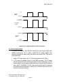
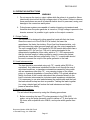
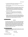
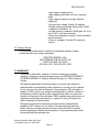
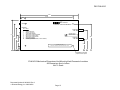
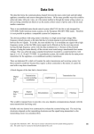
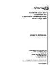
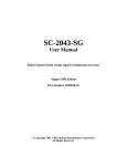
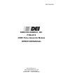
DEI PVM-4210 DIRECTED ENERGY, INC. PVM-4210 ±950V Pulse Generator Module OPERATION MANUAL Directed Energy, Inc. 2401 Research Blvd., Ste. 108 Fort Collins, Colorado 80526 970/493-1901 FAX 970/493-1903 DEI PVM-4210 DEI PVM-4210 Table Of Contents 1.0 Safety...........................................................................................................3 2.0 Overview .....................................................................................................3 3.0 Specifications..............................................................................................6 4.0 Connector Pin-Outs And User Adjustments................................................7 4.1 Polarity Reversal ...............................................................................7 4.2 Power Supply Enable ........................................................................9 5.0 OPERATING INSTRUCTIONS ....................................................................10 5.1 Output Cabling ..................................................................................10 5.2 Load Interconnection.........................................................................10 5.3 Power-Up Procedures .......................................................................10 6.0 TROUBLESHOOTING .................................................................................11 6.1 Troubleshooting Procedures .............................................................11 6.2 Factory Service .................................................................................12 7.0 WARRANTY ................................................................................................12 APPENDIX.........................................................................................................14 Mechanical Dimensions And Mounting Hole/Connector Location Drawing ...................................................................................................14 Document Number 9100-0201 Rev 8 Directed Energy, Inc. 2000-2002 Page 1 DEI PVM-4210 ********** WARNING ********** SAFE OPERATING PROCEDURES AND PROPER USE OF THE EQUIPMENT ARE THE RESPONSIBILITY OF THE USER OF THIS SYSTEM. Directed Energy, Inc (DEI) provides information on its products and associated hazards, but it assumes no responsibility for the after-sale operation and safety practices. ALL PERSONNEL WHO WORK WITH OR ARE EXPOSED TO THIS EQUIPMENT MUST TAKE PRECAUTIONS TO PROTECT THEMSELVES AGAINST POSSIBLE SERIOUS AND/OR FATAL BODILY INJURY. Document Number 9100-0201 Rev 8 Directed Energy, Inc. 2000-2002 Page 2 DEI PVM-4210 1.0 Safety The high voltage/high current nature of this device dictates the use of caution when operating or servicing this equipment. OBSERVE ALL SAFETY PRECAUTIONS LISTED BELOW. FAILURE TO DO SO COULD RESULT IN SERIOUS INJURY. Precautions: 1. The Pulser should be serviced only by personnel experienced in high voltage pulsed power systems. 2. Service personnel should be instructed to observe all safety precautions as stated in the operating instructions, and those safety precautions standard to the high voltage pulsed power community. Failure to do so could result in serious injury. 3. Do not handle the load or terminations, or remove the input or output cables, while the driver is in operation. Ensure that the high voltage power supplies have fully discharged before handling the load. Failure to observe these precautions can result in potential electric shock to personnel, arcing, and damage to the connectors and system. 4. The Pulser contains reference planes which are elevated to the potential of the output pulse. Extreme caution should be exercised when servicing the equipment. 5. Pulsed power systems are capable of random triggering via transients and therefore when the driver is turned on, or high voltage is present in the module, assume it is possible to get a pulse on the output cable. 2.0 Overview The PVM-4210 is a compact, OEM-style pulse generator module providing two simultaneous differential voltage pulses of up to ±950V (1,900V differential), with pulse rise and fall times <15 nanoseconds, and pulse widths continuously adjustable from <40 nanoseconds to DC. The pulser operates on +24VDC to +28VDC support power, and features integrated DC high voltage power supplies. The PVM-4210 is optimized for differential drive of deflection plates for electrostatic modulation of particle beams in time-of-flight mass spectrometers and accelerators. It will also drive any high impedance, capacitive load such as Pockels Cells and Q-Switches, electrodes, microchannel plates, acoustic transducers, image intensifiers and Document Number 9100-0201 Rev 8 Directed Energy, Inc. 2000-2002 Page 3 DEI PVM-4210 photomultiplier tubes. The exceptional pulse fidelity of the PVM-4210 will optimize the performance of any system in which it is used. The module provides two pulse output channels, controlled by a common control logic. When the control logic receives a gate signal, both channels pulse simultaneously. One channel pulses from ground to the positive high voltage, and the other channel pulses from ground to the negative high voltage. Therefore each output can be connected to the electrodes of a Pockels Cell or Q-Switch, or to a pair of deflection plates, providing a 1,900V differential pulse across the cell or plates. These outputs may also be inverted, to pulse from the high voltage potential to ground. The width and frequency of the output pulses follow the width and frequency of the TTL input gate. The amplitude of the output pulse voltage for each channel is independently adjustable from 0 to 950V using screwdriver-adjustable potentiometers readily accessible on the end panel of the pulser module. The PVM-4210 requires +24VDC to +28VDC support power and a TTL (into 50Ω) gate signal. For safety and control flexibility, a TTL level signal is used to enable and disable the DC power supplies. Each channel is a halfbridge (totem pole) design, offering equally fast pulse rise and fall times, low power dissipation, and virtually no over-shoot, under-shoot or ringing. The unit has over-current detection and shut-down circuitry to protect the pulse generator against potential damage due to arcs and shorts in the load or interconnect cables. The block diagram below shows the main functional blocks of the pulser: Document Number 9100-0201 Rev 8 Directed Energy, Inc. 2000-2002 Page 4 DEI PVM-4210 P1-9 +5VDC +5V P1-15 P1-6 +24V Gate Pulse +24V To Logic +75V Power Supply +15V Gate Inversion on/off Pulse Generation Over current inhibit +950V Power Supply Positive Pull Up Positive Output On Primary Drive Transformer Off Positive Pull Down O/C P1-14 HV Enable To HV Power Supplies Overcurrent Sense Output Current Sense +/- Negative Pull Down Negative Output Negative Pull Up +24V Document Number 9100-0201 Rev 8 Directed Energy, Inc. 2000-2002 Page 5 -950V Power Supply DEI PVM-4210 3.0 Specifications The pulser will meet or exceed the following specifications. All specifications are measured into a 50pF load connected to each of the two outputs with 12” (~30cm) of Belden 8218 (75Ω) coaxial cable : OUTPUT PULSE ELECTRICAL CHARACTERISTICS (Specifications Apply To Both Output Channels) Output Voltage Adjustments 0 to +950V ±5V (Channel 1), 0 to –950V ±5V (Channel 2) Screwdriver-adjustable potentiometers, End Panel Pulse Width <40ns to DC measured FWHM, controlled by input gate Pulse Rise And Fall Time ≤15ns, 10%-90% Pulse Recurrence Frequency Pulse Droop Single Shot to >20KHz continuous, 5MHz burst, controlled by input gate (1) <1% Over/Undershoot <5% Jitter <1ns Shot-to-Shot Output Voltage Throughput Delay (Delay from leading edge of input 93ns typical gate to leading edge of output pulse) Maximum Duty Cycle Continuous Maximum Average Power (Per Channel) 4W (1) Pulse Output Connectors SHV, End Panel Output Cables 12” (~30cm) Belden 8218 75Ω Coaxial Cable GATE Gate Source External Gate Input TTL into 50Ω Gate Rise Time <20ns Gate Connector DSUB, End Panel GENERAL Support Power 24VDC to 28VDC @ 600mA Maximum Current Dimensions (Excluding Connectors) 5.5”W x 11”L x 1.75”H (140mm W x 279.5mm L x 44.5mm H ) 41 Ounces (1.16 kilograms) Weight (Approximate) Specifications subject to change without notice (1) The power dissipated in each channel of the PVM-4210 when driving a capacitive load is defined by the formula CV2F, where C is the total load capacitance, including the capacitance of the load, interconnect cable, and the internal capacitance of the PVM-4210, V is the pulse voltage, and F is the pulse repetition frequency (or the total pulses per second). (For these calculations, the internal capacitance of the PVM-4210 is 125pF, and Belden 8218 cable is 21.5pf/foot.) Given the maximum power supply capability of 4W (4mA) per channel, the maximum load capacitance, frequency and/or voltage at which the PVM-4210 can operate can be approximated using this formula. At lower load capacitances and/or voltages less then 950V, the PVM-4210 can operate at Document Number 9100-0201 Rev 8 Directed Energy, Inc. 2000-2002 Page 6 DEI PVM-4210 continuous pulse recurrence frequencies greater than 20KHz. This formula is not applicable when driving non-capacitive (resistive or inductive) loads. Contact DEI for information or assistance in using the PVM-4210 with different load characteristics or impedances. 4.0 Connector Pin-Outs And User Adjustments Input And Output Connectors: DB-15 PIN Number P1 - 2 P1 - 3 Function Ground +5VDC Output For Enable Circuit (See text below) Gate TTL into 50Ω +24VDC Return (Ground) Non-inverted gate polarity select (When jumpered to pin 10) Gate/Output polarity select Inverted gate polarity select (When jumpered to pin 10) Gate Return (Ground) Power Supply Enable Input (TTL High) +24VDC to +28VDC P1 - 6 P1 - 7 P1 - 9 P1 - 10 P1 - 11 P1 - 12 P1 - 14 P1 - 15 + Pulse Out: Positive Pulse Output (SHV Connector, End Panel) - Pulse Out: Negative Pulse Output (SHV Connector, End Panel) Controls: +HV Adjust: +V Adjust, Full Counter-Clockwise = 0V -HV Adjust: -V Adjust, Full Counter-Clockwise = 0V 4.1 Polarity Reversal The output polarity can be easily selected through jumpers on pins 9, 10 and 11 of the DSUB connector. When pins 9 and 10 are jumpered together, the output is non-inverted. The output is held at ground when the pulser is not gated (i.e. the TTL gate is low). When the TTL gate is high, the output of the pulser is connected to the potential of the high voltage DC power supplies. This is shown in the figure below: Document Number 9100-0201 Rev 8 Directed Energy, Inc. 2000-2002 Page 7 DEI PVM-4210 +5V GATE INPUT GROUND + PULSE VOLTAGE OUT + PULSE OUT GROUND GROUND - PULSE OUT - PULSE VOLTAGE OUT Output Pulse Configuration With Non-Inverted Gate Selected The ouput polarity can be reversed (so that the output is held at high voltage when the gate is low, and pulsed ground when the gate is high) by jumpering pins 10 and 11 together. This is shown in the figure below: Document Number 9100-0201 Rev 8 Directed Energy, Inc. 2000-2002 Page 8 DEI PVM-4210 +5V GATE INPUT GROUND + PULSE VOLTAGE OUT + PULSE OUT GROUND GROUND - PULSE OUT - PULSE VOLTAGE OUT Output Pulse Configuration With Inverted Gate Selected 4.2 Power Supply Enable For safety and flexibility, the PVM-4210 features a power supply enable input (DSUB connector pin 14). In order to enable the DC power supplies (and therefore generate an output pulse), this input must be held HIGH. This can be done in two ways: 1. Apply a TTL high signal to pin 14. The input impedance is 5K Ohms. 2. A +5V output is available on pin 3 of the DSUB connector. This 5V output can be connected to pin 14 through a switch. In this configuration, the DC power supplies can be enabled and disabled by closing the switch between pins 3 and 14. WARNING: This 5V output should only be used for satisfying the enable signal requirements of the driver. It should not be used as a 5V source for any other purpose. Document Number 9100-0201 Rev 8 Directed Energy, Inc. 2000-2002 Page 9 DEI PVM-4210 5.0 OPERATING INSTRUCTIONS WARNING 1. Do not remove the input or output cables while the pulser is in operation. Never intentionally short-circuit the high voltage output of the pulser. Failure to observe these precautions can result in potential electric shock to personnel, arcing, and damage to the connectors and system. 4. Pulsed power systems are capable of random triggering via transients and therefore when the pulse generator is turned on, or high voltage is present in the chassis, assume it is possible to get a pulse on the output connector. 5.1 Output Cabling The PVM-4210 is designed to drive capacitive loads with fast rise times. Since the current out of the PVM-4210 is limited, the lower the capacitance, the faster the risetime. Given fixed load characteristics, only the interconnecting cable type and length will vary the output capacitance. The unit is supplied with 1 foot lengths of RG-59 coaxial cable which has a capacitance of 21.5pF per foot. The unit is series terminated in the characteristic impedance of this cable, which is 75Ω. DEI recommends that the shortest length of cable possible be used to ensure the fastest possible rise times and best pulse fidelity. Only 75Ω coaxial cable should be used to connect the output of the pulse generator to the load. 5.2 Load Interconnection The load should be connected using only 75Ω coaxial cable (RG-59 or equivalent). Any inductance introduced into the circuit through the use of wire interconnections, or impedance mismatches caused by using cable with an impedance other than 75Ω, may causing ringing on the output pulse, or a general degredation of waveform fidelity. For optimal waveform fidelity, the ends of the coaxial cable should be connected directly to the load to minimize interconnection inductance and impedance mismatches. If it is necessary to use wire leads between the coaxial cable and the load, the leads should be kept as short as possible. Twisting the leads together (i.e. using a twisted pair) will reduce the lead inductance and help to preserve waveform fidelity. 5.3 Power-Up Procedures The unit should be powered up using the following procedures: 1. Before connecting the input TTL pulse generator to the PVM-4210 pulser, set up the pulse generator output to deliver a TTL level pulse into 50 ohms, with a repetition rate <20KHz, and a pulse width greater than 45ns. Document Number 9100-0201 Rev 8 Directed Energy, Inc. 2000-2002 Page 10 DEI PVM-4210 2. Connect the input DSUB connector, and connect the output to an appropriate load, prior to applying +24VDC power. 3. Monitor the voltage across the load, utilizing an appropriate high voltage probe or attenuator. 4. Apply +24VDC to +28VDC power to the module, and apply a TTL level power supply enable signal (or close the switch to connect pin 3 to pin 14 as described above). The module should produce positive and negative output pulses with an amplitude equal to the power supply voltage, with a pulse width and pulse recurrence frequency following that of the incoming gate. 5. Adjust the output voltages using the power supply adjustment potentiometers. The voltage of each channel is independently controlled. If only one channel will be used, set the voltage of the unused channel to zero. 6. If there is no output from the module, disable the high voltage power supplies. Leave the module connected to the +24VDC input without high voltage and with all connectors in place for approximately one minute to bleed off the stored energy, then disconnect the +24VDC power to the unit and refer to the Troubleshooting Section of this manual. 6.0 TROUBLESHOOTING WARNING The module contains capacitors that are used as energy storage elements. When charged, these capacitors contain in excess of 0.02 joules of stored energy. This is sufficient energy to cause injury. Assure that the +24VDC power is disconnected from the pulser, and that the capacitor bank is fully discharged and a shorting strap installed before any repairs or adjustments are attempted. Verify with a voltmeter that all circuits are de-energized before servicing. Dangerous voltages, floating ground planes and energy storage exist at several locations in the module. Touching connections or components could result in serious injury. 6.1 Troubleshooting Procedures The table below summarizes potential problems and their solutions. If these recommendations do not resolve the problem, DEI customer service can be contacted for further assistance. SYMPTOM SOLUTIONS 1. No output pulse. -No input trigger. Document Number 9100-0201 Rev 8 Directed Energy, Inc. 2000-2002 Page 11 DEI PVM-4210 -Input trigger voltage too low. -Input trigger pulse width too short. Increase width. -Input trigger frequency too high. Reduce frequency. -No input high voltage. Check HV supplies. -Enable circuit not satisfied. Ensure that +5VDC is applied to DSUB pin 14. -No gate polarity is selected. DSUB pins 9 & 10 or pins 10 &11 must be connected. -Output not connected correctly. Check all cables and connections. -Pulser is damaged. Contact DEI customer service. 6.2 Factory Service If the procedures above fail to resolve an operational problem, please contact the factory for further assistance: DIRECTED ENERGY, INC. 2401 RESEARCH BLVD SUITE 108 FORT COLLINS, CO 80526 (970) 493-1901 FAX (970) 493-1903 7.0 WARRANTY There are no warranties, express or implied, including any implied warranty of fitness for a particular purpose nor any IMPLIED WARRANTY OF MERCHANTIBILITY made by Directed Energy, Inc. (DEI) except as follows: DEI warrants equipment manufactured by it to be free from defects in materials and/or workmanship under conditions of normal use for a period of one year from the date of shipment to the purchaser. DEI will repair or replace, at DEI's option, any product manufactured by it which is shown to be defective or fails to perform within specifications within one year from the date of shipment to the purchaser. OEM, modified and custom items of equipment are similarly warranted, for a period of ninety (90) days from date of shipment to the purchaser. Equipment claimed to be defective must be returned, transportation prepaid, to DEI's factory in Fort Collins, Colorado within the warranty period. Returns must be preauthorized by contact with DEI's customer service department. Written documentation of such preauthorization shall be included with the returned item. Document Number 9100-0201 Rev 8 Directed Energy, Inc. 2000-2002 Page 12 DEI PVM-4210 At DEI's discretion, DEI may elect to repair or replace the equipment claimed to be defective or refund the original purchase price, plus taxes and transportation charges incurred by the purchaser. This Warranty shall not apply to any product that has been: 1. Repaired, worked on, or altered by persons unauthorized by DEI; 2. Subjected to misuse, neglect, or damage by others; or 3. Connected, installed, adjusted, or used in a manner not authorized in the instructions or specifications furnished by DEI. This warranty is the purchaser's sole remedy for claimed defects in the equipment sold or manufactured by DEI. DEI's liability to the purchaser is limited to the repair or replacement of the claimed defective equipment or, at DEI's option, refund of the purchase price, taxes and transportation charges incurred by the purchaser. DEI will not be responsible for or liable to the purchaser for consequential losses or damages asserted to be attributable to a claimed defect in the equipment provided. Changes made by DEI in the design or manufacture of similar equipment which are effected subsequent to the date of shipment of the warranted equipment to the purchaser are reflective of DEI's program of constant product development and improvement and shall not be construed as an acknowledgement of deficiency in the product shipped to purchaser. DEI will be under no obligation to make any changes to product previously shipped. Document Number 9100-0201 Rev 8 Directed Energy, Inc. 2000-2002 Page 13 DEI PVM-4210 APPENDIX Mechanical Dimensions And Mounting Hole/Connector Location Drawing Document Number 9100-0201 Rev 8 Directed Energy, Inc. 2000-2002 Page 14 DEI PVM-4210 11.50 10.50 1.00 DEI + HV ADJUST PVM-4210 +/- 950V DUAL OUTPUT PULSER MODULE - HV ADJUST DB-15 PINOUT 2 3 6 7 9 10 11 12 14 15 5.80 5.00 4.30 + PULSE OUT + 950V MAX GROUND +5VDC @ 50mA OUTPUT GATE (TTL into 50 Ohms) +24VDC RETURN (GROUND) JUMPER TO PIN 10 FOR NON-INVERTING GATE / OUTPUT POLARITY SELECT JUMPER TO PIN 10 FOR INVERTING GATE RETURN (GROUND) POWER SUPPLY ENABLE/DISABLE (TTL HIGH = ENABLED) +24-28VDC @ 600mA MAX CAUTION, RISK OF ELECTRIC SHOCK 4.80 - PULSE OUT - 950V MAX 3.65 2.90 ELECTRONIC INSTRUMENT FOR USE ONLY BY QUALIFIED PERSONNEL. DO NOT REMOVE COVER DURING OPERATION. THERE ARE NO USER-SERVICABLE PARTS INSIDE. 2.15 1.00 TOP VIEW 8-32 PEM nut for mounting puposes far side. 4 places PVM-4210 Mechanical Dimensions And Mounting Hole/Connector Locations All Dimensions Are In Inches Not To Scale Document Number 9100-0201 Rev 8 Directed Energy, Inc. 2000-2002 Page 15