1
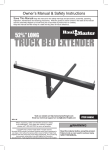
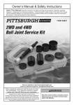
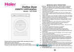
Important Safety Information
1. Assemble only according to these
instructions. Improper assembly
can create hazards.
9. Place stand on flat, level, sturdy
surface capable of supporting
stand, tool, and all workpieces.
2. Wear ANSI-approved
safety goggles and heavy-duty
work gloves during assembly.
10. Before use, secure the tool to the Tool
Stand using appropriate hardware (not
included). If tool does not bolt securely
to stand, do not use it with this stand.
3. Keep assembly area clean and well lit.
4. Keep bystanders out of the
area during assembly.
11. This product is not a toy. Do not allow
children to play with or near this item.
5. Do not assemble when tired
or when under the influence of
alcohol, drugs or medication.
12. Use as intended only.
13. Inspect before every use; do not use
if parts are loose or damaged.
6. Weight capacity and other product
capabilities apply to properly and
completely assembled product only.
14. Do not exceed listed weight capacity.
Be aware of dynamic loading!
Sudden load movement may
briefly create excess load
causing product failure.
7. Turn tool off and disconnect tool
power before attaching tool to stand.
8. Follow tool instructions for
mounting and operation.
Page 2
15. Maintain product labels and
nameplates. These carry
important safety information.
If unreadable or missing, contact
Harbor Freight Tools for a replacement.
For technical questions, please call 1-800-444-3353.
Item 69805
Specifications
Item 69805
Dimensions
18-3/8" x 20-1/2" (Top)
Up to 25.2" x 27.16" (Base – Leg Spread)
Maximum Weight Capacity
500 Lb.
Height Adjustment
3" Increments (26 –29 –32 inches)
Mounting Holes
8 Holes @ 0.310" Diameter
Leg Anchor Holes
4 Holes @ 0.310" Diameter
For technical questions, please call 1-800-444-3353.
Page 3
Assembly Instructions
Read the ENTIRE IMPORTANT SAFETY INFORMATION section at the
beginning of this document including all text under subheadings therein
before set up or use of this product.
Note: For additional information regarding the parts listed in the following
pages, refer to the Assembly Diagram near the end of this manual.
Assembling Tool Stand
1. Position the four Extension
Feet (6) on the bottom, outside
edges of the four Legs (4).
2. The height of the Tool Stand may
be adjusted to either 26, 29, or 32
inches. Slide the Extension Feet up
or down along the bottom, outside
edges of the Legs until the desired
height of the Tool Stand is reached.
Adjust the Feet to equal length.
4. Align the mounting hole located at
each end of a Bottom Long Brace (2)
with a mounting hole located on the
lower, inside edges of two Legs.
Leg (4)
Bottom Long
Brace (2)
Nut (8)
Leg (4)
Carriage
Bolt (7)
Carriage
Bolt (7)
Spring
Washer
(9)
Nut (8)
Extension
Foot
(6)
Figure 2
Figure 1
Spring Washer
(9)
3. Insert four Carriage Bolts (7) through
the four mounting holes in each
Extension Foot and Leg. Attach Spring
Washers (9), and Nuts (8) to the
Carriage Bolts and loosely tighten.
Page 4
5. Insert two Carriage Bolts through the
aligned mounting holes of the Bottom
Long Brace and two Legs. Attach
Spring Washers and Nuts to the
Carriage Bolts and loosely tighten.
6. Repeat Steps #4 and #5 above to
attach the remaining Bottom Long
Brace to the two remaining Legs.
For technical questions, please call 1-800-444-3353.
Item 69805
7. Position a Bottom Short Brace
(5) with each of its ends aligned
with the Bottom Long Braces.
8. Insert two Carriage Bolts through the
aligned mounting holes of the two
Legs and Bottom Short Brace. Attach
Spring Washers and Nuts to the
Carriage Bolts and loosely tighten.
Leg (4)
Nut (8)
Spring
Washer
(9)
Carriage
Bolt (7)
10. Align the mounting holes located at each
end of a Top Long Brace (1) with the
mounting holes located on the upper,
inside edges of two Legs. Position it
above one of the Bottom Long Braces.
11. Insert four Carriage Bolts (7) through
the aligned mounting holes of the Top
Long Brace (1) and two Legs (4). Attach
Spring Washers (9) and Nuts (8) to the
Carriage Bolts and loosely tighten.
Carriage
Bolt (7)
Top Long
Brace (1)
Nut (8)
Leg (4)
Spring
Washer
(9)
Leg (4)
Bottom Long
Brace (2)
Bottom Short
Brace (5)
Figure 3
9. Repeat Steps #7 and #8 above to
attach the remaining Bottom Short
Brace to the remaining two Legs.
Bottom Long
Brace (2)
Leg (4)
Figure 4
12. Repeat Steps #10 and #11 above
to attach the remaining Top Long
Brace to the two remaining Legs.
Item 69805
For technical questions, please call 1-800-444-3353.
Page 5
13. Position a Top Short Brace (3)
with each of its ends aligned
with the Top Long Braces.
14. Insert four Carriage Bolts through the
aligned mounting holes of the two
Legs and Top Short Brace. Attach
Spring Washers and Nuts to the
Carriage Bolts and loosely tighten.
Top Short
Brace (3)
Nut (8)
Top Long
Brace (1)
Spring
Washer
(9)
16. Place the Tool Stand at the location
where it will used. With the aid of
a corner square and a level, make
sure the top of the Tool Stand is level.
Then, wrench tighten all of the Nuts.
17. Install tool to the top of the stand,
bolting it in place in at least 4 places.
NOTE: A plywood top (not included)
may be needed as an adapter to mount
some tools. The diagram that follows
shows approximate dimensions. Also,
some tools may require a hole cut in the
plywood to allow proper ventilation or
sawdust removal — see tool instructions.
Carriage
Bolt (7)
5/8" OR 3/4" THICK PLYWOOD
13/16"
Leg (4)
7/8"
3/8" DIA.
HOLE
Bottom Long
Brace (2)
Bottom Short
Brace (5)
Figure 5
15. Repeat Steps #13 and #14 above
to attach the remaining Top Short
Brace to the remaining two Legs.
Page 6
18-3/4"
3-1/8"
4-7/32"
20-7/8"
Figure 6
For technical questions, please call 1-800-444-3353.
Item 69805
Maintenance and Servicing
TO PREVENT SERIOUS INJURY:
Disconnect the power tool(s) mounted on the Tool Stand from their
electrical or compressed air power sources before performing any
inspection, maintenance, or cleaning on the Tool Stand.
Do not use damaged equipment. If abnormal noise or vibration occurs,
turn off the tool that is mounted on the Tool Stand immediately
and have the problem corrected before further use.
Inspection, Maintenance, and Cleaning
1. BEFORE EACH USE, inspect
the general condition of the
Tool Stand. Check for:
2. To clean, wipe off stand with
slightly moist cloth.
• loose hardware
• misalignment or binding of parts
• loose or improper mounting of a tool
• cracked or broken parts
• any other condition that may
affect its safe operation.
Item 69805
For technical questions, please call 1-800-444-3353.
Page 7
Record Serial Number Here:
Note: If product has no serial number, record month and year of purchase instead.
Note: Some parts are listed and shown for illustration purposes only,
and are not available individually as replacement parts.
Page 8
For technical questions, please call 1-800-444-3353.
Item 69805
PLEASE READ THE FOLLOWING CAREFULLY
THE MANUFACTURER AND/OR DISTRIBUTOR HAS PROVIDED THE PARTS LIST AND ASSEMBLY
DIAGRAM IN THIS DOCUMENT AS A REFERENCE TOOL ONLY. NEITHER THE MANUFACTURER
OR DISTRIBUTOR MAKES ANY REPRESENTATION OR WARRANTY OF ANY KIND TO THE
BUYER THAT HE OR SHE IS QUALIFIED TO MAKE ANY REPAIRS TO THE PRODUCT, OR
THAT HE OR SHE IS QUALIFIED TO REPLACE ANY PARTS OF THE PRODUCT. IN FACT, THE
MANUFACTURER AND/OR DISTRIBUTOR EXPRESSLY STATES THAT ALL REPAIRS AND PARTS
REPLACEMENTS SHOULD BE UNDERTAKEN BY CERTIFIED AND LICENSED TECHNICIANS,
AND NOT BY THE BUYER. THE BUYER ASSUMES ALL RISK AND LIABILITY ARISING OUT OF
HIS OR HER REPAIRS TO THE ORIGINAL PRODUCT OR REPLACEMENT PARTS THERETO,
OR ARISING OUT OF HIS OR HER INSTALLATION OF REPLACEMENT PARTS THERETO.
Item 69805
For technical questions, please call 1-800-444-3353.
Page 9
Parts List
Part
1
2
3
4
5
6
7
8
9
Page 10
Description
Top Long Brace 19.69" (500mm)
Bottom Long Brace 23.74" (603mm)
Top Short Brace 17.71" (450mm)
Leg 26.38" (670mm)
Bottom Short Brace 21.77" (553mm)
Extension Foot 9.76" (248mm)
Carriage Bolt M6
Nut M6
Spring Washer Ø6
Qty.
2
2
2
4
2
4
40
40
40
For technical questions, please call 1-800-444-3353.
Item 69805
Assembly Diagram
8
9
7
3
1
4
5
2
6
Item 69805
For technical questions, please call 1-800-444-3353.
Page 11
Limited 90 Day Warranty
Harbor Freight Tools Co. makes every effort to assure that its products meet high quality
and durability standards, and warrants to the original purchaser that this product is free from
defects in materials and workmanship for the period of 90 days from the date of purchase.
This warranty does not apply to damage due directly or indirectly, to misuse, abuse, negligence
or accidents, repairs or alterations outside our facilities, criminal activity, improper installation,
normal wear and tear, or to lack of maintenance. We shall in no event be liable for death,
injuries to persons or property, or for incidental, contingent, special or consequential damages
arising from the use of our product. Some states do not allow the exclusion or limitation of
incidental or consequential damages, so the above limitation of exclusion may not apply to you.
THIS WARRANTY IS EXPRESSLY IN LIEU OF ALL OTHER WARRANTIES, EXPRESS OR
IMPLIED, INCLUDING THE WARRANTIES OF MERCHANTABILITY AND FITNESS.
To take advantage of this warranty, the product or part must be returned to us with transportation
charges prepaid. Proof of purchase date and an explanation of the complaint must accompany
the merchandise. If our inspection verifies the defect, we will either repair or replace
the product at our election or we may elect to refund the purchase price if we cannot readily
and quickly provide you with a replacement. We will return repaired products at our expense,
but if we determine there is no defect, or that the defect resulted from causes not within
the scope of our warranty, then you must bear the cost of returning the product.
This warranty gives you specific legal rights and you may also
have other rights which vary from state to state.
3491 Mission Oaks Blvd. • PO Box 6009 • Camarillo, CA 93011 • (800) 444-3353