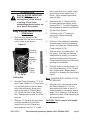
1
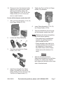
Multi-purpose electric
sharpener
Model 99823
Set up and Operating Instructions
Visit our website at: http://www.harborfreight.com
Read this material before using this product.
Failure to do so can result in serious injury.
Save this manual.
Copyright© 2008 by Harbor Freight Tools®. All rights reserved. No portion of this manual or any artwork
contained herein may be reproduced in any shape or form without the express written consent of Harbor
Freight Tools. Diagrams within this manual may not be drawn proportionally. Due to continuing improvements, actual product may differ slightly from the product described herein. Tools required for assembly
and service may not be included.
For technical questions or replacement parts, please call 1-800-444-3353.
Manual Revised 10e
Save This Manual
CAUTION, used
with the safety
alert symbol, indicates a
hazardous situation which, if
not avoided, could result in
minor or moderate injury.
Keep this manual for the safety
warnings and precautions, assembly,
operating, inspection, maintenance and
cleaning procedures. Write the product’s
serial number in the back of the manual
near the assembly diagram (or month
and year of purchase if product has no
number). Keep this manual and the
receipt in a safe and dry place for future
reference.
NOTICE is used to
address practices
not related to personal injury.
CAUTION, without
the safety alert
symbol, is used to address
practices not related to
personal injury.
Important Safety
Instructions
Read and understand all
instructions
In this manual, on the labeling,
and all other information
provided with this product:
This is the safety alert
symbol. It is used to alert
you to potential personal
injury hazards. Obey all
safety messages that
follow this symbol to avoid
possible injury or death.
DANGER indicates
a hazardous
situation which, if not
avoided, will result in death or
serious injury.
WARNING
indicates a
hazardous situation which, if
not avoided, could result in
death or serious injury.
When using electrical tools,
safety precautions should
always be followed including the
following:
Work Area Safety
1.
Do not use outdoors.
2.
Close supervision is necessary when
any tool is used by or near children.
3.
Do not let cord hang over edge
of table or counter, or touch hot
surfaces.
4.
Do not place on or near a hot gas or
electric burner, or in a heated oven.
5.
Extreme caution must be used when
moving an tool.
6.
Keep the work area well lit. Make
sure there is adequate surrounding
workspace. Keep the work area free
of obstructions and other debris.
SKU 99823
For technical questions, please call 1-800-444-3353.
Page 2
tripping over a longer cord.
Electrical Safety
1.
To protect against
electrical shock do not
immerse cord, plugs, or
the main unit in water or
other liquid. Only the
non-electrical parts of the unit may be
immersed for cleaning. Thoroughly
clean and dry these parts prior to first
use and before every subsequent
use.
2.
Unplug from outlet when not in use
and before maintenance or cleaning.
3.
Do not operate any tool with a
damaged cord or plug or after the tool
malfunctions or has been damaged
in any manner. Return tool to the
nearest authorized service facility for
examination, repair, or adjustment.
4.
This Electric Sharpener has a
polarized plug (one blade is wider
than the other). To reduce the risk of
electric shock, this plug is intended
to fit into a polarized outlet only one
way. If the plug does not fit fully
in the outlet, reverse the plug. If it
still does not fit, contact a qualified
electrician. Do not change the plug in
any way.
5.
Do not use this product in a damp or
wet location.
6.
Do not clean with metal scouring
pads. Metal pieces can break off
the pads and touch electrical parts
involving risk of shock.
Power Cord Safety
1.
A short power supply cord is to be
provided to reduce risks resulting
from becoming entangled in or
SKU 99823
2.
Longer extension cords are available
and may be used if care is exercised
in their use.
3.
If a long extension cord is used,
a.the marked electrical rating of the
(detachable power supply cord or)
extension cord should be at least as
great as the electrical rating of the
tool,
b.if the tool is of the grounded type,
the extension cord should be a
grounding type 3-wire cord, and
c. the longer cord should be arranged
so that it will not drape over the
counter top or tabletop where it can
be pulled on by children or tripped
over.
General Safety
1.
The use of accessory attachments
not recommended by the tool
manufacturer may cause injuries.
2.
To disconnect, turn any control to
“off”, then remove plug from wall
outlet.
3.
Do not use tool for other than
intended use.
4.
Maintain labels and nameplates on
the tool. These carry important safety
information. If unreadable or missing,
contact Harbor Freight Tools for a
replacement.
5.
Do not store anything other than
the manufacturer’s recommended
accessories in this unit when not in
use.
For technical questions, please call 1-800-444-3353.
Page 3
6.
This product is not a toy. Keep it out
of reach of children when children are
not being closely supervised.
3.
Knives with serrated edges are a
good example of blades that may not
be suited for this Electric Sharpener.
7.
People with pacemakers should
consult their physician(s) before
use. Electromagnetic fields in close
proximity to heart pacemaker could
cause pacemaker interference or
pacemaker failure.
4.
This Multi-purpose Electric Sharpener
is not recommended for professional
applications.
8.
9.
WARNING: The brass components
of this product contain lead, a
chemical known to the State of
California to cause birth defects (or
other reproductive harm). (California
Health & Safety code § 25249.5, et
seq.)
WARNING: Handling the cord on
this product will expose you to lead,
a chemical known to the State of
California to cause cancer, and
birth defects or other reproductive
harm. Wash hands after handling.
(California Health & Safety Code §
25249.5, et seq.)
10. The warnings, precautions, and
instructions discussed in this
instruction manual cannot cover all
possible conditions and situations
that may occur. It must be understood
by the operator that common sense
and caution are factors which cannot
be built into this product, but must be
supplied by the operator.
Save these
instructions.
Specifications
Electrical
Requirements
120 V~ / 60 Hz / 70 W
Cord Length
6’ L
Speed
4800 RPM
Switch
Rocker Type ON/OFF
Applications
Drill Bits: 1/8” ~ 3/8”
(3~10mm)
Chisels/Planer Blades:
1/4” ~ 2” W
Most Knives and Scissors.
Minimum size drill bit 1/8”
Unpacking
When unpacking, check to make sure
that the item is intact and undamaged. If
any parts are missing or broken, please
call Harbor Freight Tools at the number
shown on the cover of this manual as soon
as possible.
Specific Safety Rules
1.
Grinding wheel MUST BE rated to
at least 4800 RPM.
2.
Wear ANSI-approved safety
goggles and heavy-duty work
gloves during set up and use.
REV 08k
SKU 99823
For technical questions, please call 1-800-444-3353.
Page 4
Assembly
Figure 2
Read the entire Important
Safeguards section at
the beginning of this manual
including all text under
subheadings therein before set
up or use of this product.
To prevent
serious injury
from accidental
operation or electric
shock:
Before tool assembly or
adjustment, make sure the
tool’s switch is turned off, and
the cord is unplugged.
b.High speed Drill Bit Attachment.
Figure 3
Note: For additional information regarding
the parts listed in the following pages,
refer to the Assembly Diagram near
the end of this manual.
Assembling the Sharpening
Attachments
1.
There are three sharpening
Attachments for this Multi-purpose
Electric Sharpener:
c.Straight Edge Chisel and Plane
Blade Attachment.
2.
All three Attachments can be easily
snapped on and off the front of
the Electric Sharpener. Slide the
Attachment into or out of the grooved
channels on each side of the Motor
Housing. All three snap in place.
Figure 1
a.Standard Knife and Scissor
Attachment.
SKU 99823
For technical questions, please call 1-800-444-3353.
Page 5
the bit so that all four corners of the
bit would touch the walls of the “V”
Guide. (Only sharpen Right Hand
twist drill bits)
Operation
Read the entire Important
Safeguards section at
the beginning of this manual
including all text under
subheadings therein before set
up or use of this product.
1.
4.
Using the High Speed Drill Bit
Attachment
Ease back the “V” Guide until the
bit rests against the stopper at the
center of the “V”. Turn the Clamping
Nut clockwise to securely hold the bit
(Do Not Over-tighten).
5.
Slide the High Speed Drill Bit
Attachment onto the Motor Housing
until it snaps at the bottom.
Pull back on the “V” Guide and
remove the Clamp Assembly
(17,18,19).
6.
Push top of the sharpener assembly
forward (away from the sharpening
stone), and insert the Clamp into the
Clamp Holder (15,16).
7.
Start the motor by pushing the “I” on
the switch. Wait until the grindingwheel picks up speed. In a uniform,
slow and steady motion swing the
Clamp Assembly back and forth until
grinding noise subsides.
8.
Turn the switch to its off position. Lift
the Clamp Assembly (17,18,19) and
flip it upside down. Repeat steps 6
through 8 to sharpen the other face of
the bit.
Figure 4
Grinding
Wheel (6)
Clamp
Assembly
(17, 18,
19)
“V” Guide
Setting Slot
Clamp
Holder
(15,16)
2.
Remove Clamp Assembly (17,18,19)
from Clamp Holder (15,16) and insert
it in the Setting Slot at the left hand
side of the module by aligning the
slots at the sides of Clamp Holder
(15,16) with the tabs of the Setting
Slot. Clamping nut should be on the
top side.
3.
Slide the “V” Guide all the way down
and hold in place with one hand.
Insert the bit into the Clamp and
while pushing it into the “V”, rotate
SKU 99823
Note: SHARPEN BOTH FACES OF THE
BIT EQUALLY.
9.
Stop the motor, remove the bit with
the Clamp Assembly (17,18,19)
and inspect both faces of the bit. If
further grinding is necessary, repeat
steps 3 to 8. However, if the result is
satisfactory, back off the clamping nut
and remove the bit.
CAUTION: The bit may be hot. Handle
with care.
For technical questions, please call 1-800-444-3353.
Page 6
10. Disconnect from the electrical outlet,
wipe the unit to remove dust, metal
shavings and debris. Return the
Clamp Assembly (17,18,19) into the
Clamp Holder (15,16). Cover and
store in a safe location.
5.
Tighten the Top Lock Nut for Clamp
Holder (19) clockwise;
6.
Insert Clamp Assembly (17,18,19)
into Clamp Holder (15,16);
7.
Then the attachment can be for the
drill bit diameter smaller than 9/64”.
For the drill bit diameter smaller than 9/64”
1.
Take out Clamp Assembly (17,18,19)
from Clamp Holder (15,16);
NOTE: Mastering the setup and grinding
the bit will require practice.
2.
3.
Loosen the Clamp Assembly;
• The module may be pulled back
towards the grinding wheel for
faster material removal,
• Clamp assembly may need to be
inserted partially and as the faces
are sharpened, it may need to
be pushed down until the Clamp
Holder rests at the bottom of its
cavity.
Turn the Locking Nut for Clamp
Holder (18) in 180°;
Knives
1.
4.
Slide the Scissors and KnifeSharpening attachment into the Motor
Housing (1), making sure that the
latch snaps into the catch at the lower
side of the attachment.
Insert the Locking Nut for Clamp
Holder (18) with Top Lock Nut for
Clamp Holder (19) into the slot of the
Turn Nut for Clamp Holder (17);
SKU 99823
For technical questions, please call 1-800-444-3353.
Page 7
2.
Switch the Motor on.
latch snaps into the catch at the lower
side of the attachment.
Figure 5
Guide
Slots
3.
Hold the knife handle towards you
and insert the heel end of the blade
into the Guide Slot. See Figure 5 for
all directions in this section.
4.
As soon as the blade touches the
Grinding Wheel (6), slide it with light,
even pressure across the Grinding
Wheel (6) surface to the knife tip,
then remove it. Do not use excess
pressure.
5.
Insert the other side of the knife into
the opposite guide slot and repeat
the same procedure as in number 3
above.
6.
Continue this procedure alternating
sides of the knife blade until a sharp
edge is attained.
7.
Turn off the power to the Motor
Housing with Switch (3).
3.
Turn on the Power Switch (3) and
allow the motor speed to stabilize.
4.
Open the scissors fully. Note: This
tool can only sharpen those scissors
which spread fully (past 90°).
5.
Keeping the idle blade to the right
hand side of the Motor Housing (1),
position the underside of the blade
to be sharpened in the slot across
the face of the Attachment. Position
the blade edge parallel to the right
hand side of the grinding wheel and
with very light pressure slide the
entire length of the blade across the
grinding wheel.
6.
Repeat Step 4 above to sharpen
the other blade. Alternate between
blades until a keen edge is formed
across the edges. Remove scissors
from the sharpener
7.
Turn off the Power Switch (3).
Using Scissors Attachment
1.
Slide the Scissors and KnifeSharpening attachment into the Motor
Housing (1), making sure that the
latch snaps into the catch at the lower
side of the attachment.
2.
Attach the Scissors and Knife
Sharpening Attachment to the
grinding wheel side of the Motor
Housing (1), making sure that the
SKU 99823
For technical questions, please call 1-800-444-3353.
Page 8
Using the Chisel and Plane
Attachment
Figure 6
Support Plate with
Magnets (29)
4.
Turn on the Power Switch (3) and
allow the motor speed to stabilize.
5.
Slide the Support Plate, making sure
that blade edge touches the wheel.
Note: Do not force the blade onto the
Grinding Wheel.
Motor Housing (1)
6.
Stop the motor and remove the
blade to inspect for proper and
uniform bevel angle and sharp edge.
If necessary, bevel angle may be
slightly re-adjusted.
7.
When sharpening cold chisels, stop
the Motor, turn the blade upside
down, repeat steps 4 through 6 to
sharpen the other face.
8.
To prevent accidents, after each use
turn off the tool and disconnect it for
its power supply. Clean, then store
indoors out of children’s reach.
Base with Mounting
Holes (2)
1.
2.
Slide the Chisel and Plane
sharpening attachment into the Motor
Housing (1), making sure that the
latch snaps into the catch at the lower
side of the attachment.
Determine the existing blade bevel
angle, back off the thumb screw and
slide the guide platform to the desired
angle, using the scale and indicator
on the face of the attachment.
Tighten the thumb screw.
NOTE: For extra fine edge, use of whet
stone and honing oil is recommended
after completion of sharpening with
this tool.
Note: To redress the edge to an alternative
angle, use of a heavy-duty grinding
set-up is recommended.
3.
Position the chisel against the side
lip of the Support Plate (29) and slide
the chisel edge down to reach the
grinding wheel.
Note: The chisel should be perpendicular
to the grinding wheel. The magnet
on the Support Plate will support the
blade in position during set up, but
the blade must be held firmly by hand
during actual grinding.
SKU 99823
For technical questions, please call 1-800-444-3353.
Page 9
To prevent serious
injury from failure:
Do not use if damaged. If
abnormal noise or vibration
occurs, have the problem
corrected before further use.
INSPECTION and
MAINTENANCE
To prevent
serious injury
from accidental
operation or electric
shock:
Before inspection or
maintenance, make sure the
switch is turned off, and the
cord is unplugged.
BEFORE EACH USE, inspect the
general condition of the Electric
Sharpener. Check for loose screws,
misalignment or binding of moving
parts, cracked or broken parts,
damaged electrical wiring, and any
other condition that may affect its
safe operation.
Troubleshooting
Problem
Possible Causes
Likely Solutions
Electric Sharpener will 1. No power at outlet.
1. Check power at outlet.
not start
2. Cord not connected.
2. Check that cord is plugged in.
Grinding Wheel not
3. Grinding Wheel may not be true due 4. Check Grinding Wheel for smooth,
running smoothly
to wear during use.
straight edge and replace if
necessary.
Follow all safety precautions whenever diagnosing or servicing the
tool. Disconnect power supply before service.
PLEASE READ THE FOLLOWING CAREFULLY
The manufacturer and/or distributor has provided the parts list and assembly
diagram in this manual as a reference tool only. Neither the manufacturer or
distributor makes any representation or warranty of any kind to the buyer that
he or she is qualified to make any repairs to the product, or that he or she is
qualified to replace any parts of the product. In fact, the manufacturer and/
or distributor expressly states that all repairs and parts replacements should
be undertaken by certified and licensed technicians, and not by the buyer. The
buyer assumes all risk and liability arising out of his or her repairs to the
original product or replacement parts thereto, or arising out of his or her
installation of replacement parts thereto.
Record Product’s Serial Number Here:
Note: If product has no serial number, record month and year of purchase instead.
Note: Some parts are listed and shown for illustration purposes only, and are not
available individually as replacement parts.
SKU 99823
For technical questions, please call 1-800-444-3353.
Page 10
PARTS LIST
Part
1
2
3
4
5
6
7
8
9
10
11
12
13
14
15
16
17
18
Description
Motor Housing
Base (with mounting holes)
Switch (Rocker type ON/OFF)
Motor
Wheel Valve
Grinding Wheel
Sign for Rotational Direction
Nut
Power Cord
Cable Jacket
Screw
PCB
Rubber Foot
Screw
Clamp Holder
Clamp
Turn Nut for Clamp Holder
Locking Nut for Clamp Holder
PARTS LIST
Q’ty
1
1
1
1
1
1
1
1
1
1
2
1
4
4
1
1
1
1
Part
19
21
22
23
24
25
26
27
28
29
30
31
32
33
34
Description
Top Lock Nut for Clamp Holder
Located Block
Screw
Back Plate for “V” Guide
High Speed Drill Bit Attachment
Standard Knife and Scissors
Attachment
Straight Edge Chisel and Plane
Blade Attachment
Lock Nut
Angle Plate
Blade Support Shelf
Move Plate
Protective Guard
Magnet Guard
Magnet
Screw
Q’ty
1
1
1
1
1
1
1
1
1
1
1
1
2
1
1
ASSEMBLY DIAGRAM
SKU 99823
For technical questions, please call 1-800-444-3353.
Page 11
LIMITED 90 DAY WARRANTY
Harbor Freight Tools Co. makes every
effort to assure that its products meet
high quality and durability standards, and
warrants to the original purchaser that this
product is free from defects in materials
and workmanship for the period of 90 days
from the date of purchase. This warranty
does not apply to damage due directly or
indirectly, to misuse, abuse, negligence or
accidents, repairs or alterations outside
our facilities, criminal activity, improper
installation, normal wear and tear, or to
lack of maintenance. We shall in no event
be liable for death, injuries to persons
or property, or for incidental, contingent,
special or consequential damages arising
from the use of our product. Some states
do not allow the exclusion or limitation
of incidental or consequential damages,
so the above limitation of exclusion may
not apply to you. This warranty is
expressly in lieu of all other
warranties, express or implied,
including the warranties of
merchantability and fitness.
SKU 99823
To take advantage of this warranty,
the product or part must be returned to
us with transportation charges prepaid.
Proof of purchase date and an explanation
of the complaint must accompany the
merchandise. If our inspection verifies
the defect, we will either repair or replace
the product at our election or we may
elect to refund the purchase price if
we cannot readily and quickly provide
you with a replacement. We will return
repaired products at our expense, but if we
determine there is no defect, or that the
defect resulted from causes not within the
scope of our warranty, then you must bear
the cost of returning the product.
This warranty gives you specific legal
rights and you may also have other rights
which vary from state to state.
3491 Mission Oaks Blvd. • PO Box 6009
Camarillo, CA 93011 • (800) 444-3353
For technical questions, please call 1-800-444-3353.
Page 12