1
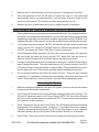
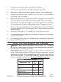
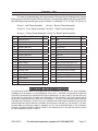
Auto A/C Recovery /
Recharge Machine
Model 95951
Set up And Operating Instructions
Diagrams within this manual may not be drawn proportionally.
Due to continuing improvements, actual product may differ slightly from the product described herein.
Distributed exclusively by Harbor Freight Tools®.
3491 Mission Oaks Blvd., Camarillo, CA 93011
Visit our website at: http://www.harborfreight.com
Read this material before using this product.
Failure to do so can result in serious injury.
Save this manual.
Copyright© 2007 by Harbor Freight Tools®. All rights reserved. No portion of this
manual or any artwork contained herein may be reproduced in any shape or form
without the express written consent of Harbor Freight Tools.
For technical questions or replacement parts, please call 1-800-444-3353.
Specifications
Construction
Sheet Steel Housing, Reinforced Braided Rubber
Hoses with Brass Fittings, Polypropylene Valves,
Copper Tubing, Thermoplastic Oil Bottle and
Carbon Steel Hardware
Electrical Requirements
110 V~, 60 Hz
Compressor
1/3 HP Input Power
Vacuum Maximum Capacity
60 Liters per Minute (15.9 Gallons per minute)
Suitable for
R134A Refrigerant
Refrigerant Tank Capacity
14 kg (30.8 lb)
Maximum Scale Weight
30 kg (66 lb)
Recovery Speed
250 Grams/Min (8.82 Ounces per Minute)
Refilling Speed
800 G/Min (28 Ounces per Minute)
Overall Dimensions
18-1/8” W x 22” D x 43-1/8” H
Net Weight
160.8 lb.
Save This Manual
You will need this manual for the safety warnings and precautions, assembly, operating, inspection, maintenance and cleaning procedures, parts list and assembly diagram.
Keep your invoice with this manual. Write the invoice number on the inside of the front
cover. Write the product’s serial number in the back of the manual near the assembly
diagram, or write month and year of purchase if product has no number. Keep this manual
and invoice in a safe and dry place for future reference.
GENERAL SAFETY RULES
WARNING!
READ AND UNDERSTAND ALL INSTRUCTIONS
Failure to follow all instructions listed below may result in
electric shock, fire, and/or serious injury.
SAVE THESE INSTRUCTIONS
Work Area
1.
Keep your work area clean and well lit. Cluttered benches and dark areas invite
accidents.
2.
Do not operate powered machines in explosive atmospheres, such as in the
presence of flammable liquids, gases, or dust. Power machines create sparks
which may ignite the dust or fumes.
SKU 95951
For technical questions, please call 1-800-444-3353.
Page 2
3.
Keep bystanders, children, and visitors away while operating a powered machine. Distractions can cause you to lose control. Protect others in the work area
from debris fumes and oil. Provide barriers or shields as needed.
Electrical Safety
1.
Grounded machines must be plugged into an outlet properly installed and
grounded in accordance with all codes and ordinances. Never remove the
grounding prong or modify the plug in any way. Do not use any adapter plugs.
Check with a qualified electrician if you are in doubt as to whether the outlet is
properly grounded. If the machines should electrically malfunction or break down,
grounding provides a low resistance path to carry electricity away from the user.
2.
Double insulated machines are equipped with a polarized plug (one blade is
wider than the other). This plug will fit in a polarized outlet only one way. If
the plug does not fit fully in the outlet, reverse the plug. If it still does not
fit, contact a qualified electrician to install a polarized outlet. Do not change
the plug in any way. Double insulation eliminates the need for the three wire
grounded power cord and grounded power supply system.
3.
Avoid body contact with grounded surfaces such as pipes, radiators, ranges,
and refrigerators. There is an increased risk of electric shock if your body is
grounded.
4.
Do not expose powered machines to rain or wet conditions. Water entering a
powered machine will increase the risk of electric shock.
5.
Do not abuse the Power Cord. Never use the Power Cord to carry the machines
or pull the Plug from an outlet. Keep the Power Cord away from heat, oil,
sharp edges, or moving parts. Replace damaged Power Cords immediately.
Damaged Power Cords increase the risk of electric shock.
6.
When operating a powered machine outside, use an outdoor extension cord
marked “W-A” or “W”. These extension cords are rated for outdoor use, and
reduce the risk of electric shock.
Personal Safety
1.
Stay alert. Watch what you are doing, and use common sense when operating a powered machine. Do not use a powered machine while tired or under
the influence of drugs, alcohol, or medication. A moment of inattention while
operating powered machines may result in serious personal injury.
2.
Dress properly. Do not wear loose clothing or jewelry. Contain long hair. Keep
your hair, clothing, and gloves away from moving parts in engine compartment.
Loose clothes, jewelry, or long hair can be caught in moving parts in the machine.
SKU 95951
For technical questions, please call 1-800-444-3353.
Page 3
3.
Avoid accidental starting. Be sure the Power Switch is off before plugging in.
Leaving the Power Switch on while the machine is unattended invites accidents.
4.
Remove adjusting keys or wrenches before turning the powered machine on.
A wrench or a key that is left attached to a rotating part of the powered machine
may result in personal injury.
5.
Do not overreach. Keep proper footing and balance at all times. Proper footing and balance enables better control of the powered machine in unexpected
situations.
6.
Use safety equipment. Always wear eye protection. Dust mask, nonskid safety
shoes, hard hat, or hearing protection must be used for appropriate conditions. Always wear ANSI-approved safety goggles and a dust mask/respirator when using
or performing maintenance on this machine. Keep the work area well ventilated.
Tool Use And Care
1.
Do not force the machine. Use the correct machine for your application. The
correct machine will do the job better and safer at the rate for which it is designed.
Do not force the machine and do not use the machine for a purpose for which it is
not intended.
2.
Do not use the powered machine if the Power Switch does not turn it on or
off. Any machine that cannot be controlled with the Power Switch is dangerous
and must be replaced.
3.
Disconnect the Power Cord Plug from the power source before making any
adjustments, changing accessories, or storing the machine. Such preventive
safety measures reduce the risk of starting the machine accidentally. Always unplug the machine from its electrical outlet before performing any inspection,
maintenance, or cleaning procedures.
4.
Store idle machines out of reach of children and other untrained persons.
Tools are dangerous in the hands of untrained users.
5.
Maintain machines with care. Properly maintained machines are less likely to fail
and are easier to control. Do not use a damaged machine. Tag damaged machines
“Do not use” until repaired.
6.
Check for misalignment or binding of moving parts, breakage of parts, and
any other condition that may affect the machine’s operation. If damaged,
have the machine serviced before using. Many accidents are caused by poorly
maintained machines.
7.
Use only accessories that are recommended by the manufacturer for your
model. Accessories that may be suitable for one machine may become hazardous
when used on another machine.
SKU 95951
For technical questions, please call 1-800-444-3353.
Page 4
Service
1.
Tool service must be performed only by qualified repair personnel. Service or
maintenance performed by unqualified personnel could result in a risk of injury.
2.
When servicing a machine, use only identical replacement parts. Follow
instructions in the “Inspection, Maintenance, And Cleaning” section of this
manual. Use of unauthorized parts or failure to follow maintenance instructions
may create a risk of electric shock or injury.
SPECIFIC SAFETY RULES
1.
Maintain labels and nameplates on the machine. These carry important information. If unreadable or missing, contact Harbor Freight Tools for a replacement.
2.
Maintain a safe working environment. Make sure there is adequate surrounding workspace. Do not use this product in a damp or wet location. Be sure there is
adequate ventilation. Do not operate machine or vehicle in enclosed space.
3.
When using a handheld powered machine, always maintain a firm grip on the
machine with both hands to resist starting torque.
4.
Avoid unintentional starting. Make sure you are prepared to begin work before
turning on the machine.
5.
Always keep the extension cord away from moving parts on the machine or
the vehicle.
6.
People with pacemakers should consult their physician(s) before using this
product. Electromagnetic fields in close proximity to a heart pacemaker could cause
interference to or failure of the pacemaker. In addition, people with pacemakers
should adhere to the following:
• Avoid operating powered machines alone.
• Don’t use a powered machine with the power switch locked on.
• If powered via a power cord be certain that the machine is properly grounded. A
ground fault interrupt (GFCI) system is also a good precaution. This inexpensive device is a good safety measure because it prevents a sustained electrical shock.
• Properly maintain and inspect all machines before use to avoid electrical
shock.
7.
Only use R134A refrigerant with this machine. Do not use other refrigerants.
Please see refrigerant discussion on page 12 of this manual for more information.
Before servicing, check vehicle owner’s manual to confirm that A/C system will
operate on R134A refrigerant.
8.
Before starting service, check to see that the recovery tank has space for additional coolant, there is replacement refrigerant in the coolant tank, and there
REV 08k
SKU 95951
For technical questions, please call 1-800-444-3353.
Page 5
is cooling oil in the cooling oil bottle. Check compressor oil level to determine
it is within safe limits before starting service.
9.
Do not expose this machine to direct sunlight or rain. Keep it in a well ventilated
sheltered area.
10.
The refrigerant tank may only be filled to 80% capacity during the recovery
operation. Check tank level before starting service to ensure that there is sufficient
recovery space.
11.
There must be at least 1 kg (2.2 lb) of refrigerant in the coolant tank to perform
the refilling operation. Do not attempt the refilling operation if there is less than 1
kg (2.2 lb) of refrigerant in the coolant tank.
12.
The HP and LP Valves on the Control Panel must be in the CLOSED position
when attaching the machine to the auto A/C system.
13.
When servicing, keep all hoses away from hot parts and moving components
of vehicle engine area to prevent hose damage.
14.
When running the vehicle, be sure it is in PARK or NEUTRAL with parking
brakes locked and wheels chocked.
15.
Never start the vehicle or operate the vehicle A/C system if the hose is connected to the HP system and the HP Valve on the Control Panel is open.
16.
WARNING: The brass components of this product contain lead, a chemical
known to the State of California to cause birth defects (or other reproductive
harm). (California Health & Safety code § 25249.5, et seq.)
GROUNDING
WARNING!
Improperly connecting the grounding wire can result in the risk of electric shock.
Check with a qualified electrician if you are in doubt as to whether the outlet is
properly grounded. Do not modify the power cord plug provided with the tool.
Never remove the grounding prong from the plug. Do not use the tool if the
power cord or plug is damaged. If damaged, have it repaired by a service facility before use. If the plug will not fit the outlet, have a proper outlet installed by
a qualified electrician.
Grounded Tools: Tools With Three Prong Plugs
1.
Tools marked with “Grounding Required” have a three wire cord and three prong
grounding plug. The plug must be connected to a properly grounded outlet. If the
machine should electrically malfunction or break down, grounding provides a low
REV 08a
SKU 95951
For technical questions, please call 1-800-444-3353.
Page 6
resistance path to carry electricity away from the user, reducing the risk of electric
shock. (See 3-Prong Plug and Outlet.)
2.
The grounding prong in the plug is connected through the green wire inside the
cord to the grounding system in the machine. The green wire in the cord must be
the only wire connected to the machine’s grounding system and must never be attached to an electrically “live” terminal. (See 3-Prong Plug and Outlet.)
3.
Your machine must be plugged into an appropriate outlet, properly installed and
grounded in accordance with all codes and ordinances. The plug and outlet should
look like those in the following illustration. (See 3-Prong Plug and Outlet.)
3-Prong Plug and Outlet
Outlets for 2-Prong Plug
Double Insulated Tools: Tools With Two Prong Plugs
1.
Tools marked “Double Insulated” do not require grounding. They have a special
double insulation system which satisfies OSHA requirements and complies with the
applicable standards of Underwriters Laboratories, Inc., the Canadian Standard
Association, and the National Electrical Code. (See Outlets for 2-Prong Plug.)
2.
Double insulated machines may be used in either of the 120 volt outlets shown in
the preceding illustration. (See Outlets for 2-Prong Plug.)
Extension Cords
1.
Grounded machines require a three wire extension cord. Double Insulated machines can use either a two or three wire extension cord.
2.
As the distance from the supply outlet increases, you must use a heavier gauge
extension cord. Using extension cords with inadequately sized wire causes a serious drop in voltage, resulting in loss of power and possible machine damage.
(See Table A.)
3.
The smaller the gauge number of the wire, the greater the capacity of the cord. For
example, a 14 gauge cord can carry a higher current than a 16 gauge cord.
(See Table A.)
4.
When using more than one extension cord to make up the total length, make sure
each cord contains at least the minimum wire size required. (See Table A.)
SKU 95951
For technical questions, please call 1-800-444-3353.
Page 7
5.
If you are using one extension cord for more than one machine, add the nameplate
amperes and use the sum to determine the required minimum cord size.
(See Table A.)
6.
If you are using an extension cord outdoors, make sure it is marked with the suffix
“W-A” (“W” in Canada) to indicate it is acceptable for outdoor use.
7.
Make sure your extension cord is properly wired and in good electrical condition.
Always replace a damaged extension cord or have it repaired by a qualified electrician before using it.
8.
Protect your extension cords from sharp objects, excessive heat, and damp or wet
areas.
RECOMMENDED MINIMUM WIRE GAUGE FOR EXTENSION CORDS*
(120 or 240 VOLT)
NAMEPLATE
AMPERES
EXTENSION CORD LENGTH
(at full load)
25 Feet
50 Feet
75 Feet
100 Feet
150 Feet
0 – 2.0
18
18
18
18
16
2.1 – 3.4
18
18
18
16
14
3.5 – 5.0
18
18
16
14
12
5.1 – 7.0
18
16
14
12
12
7.1 – 12.0
18
14
12
10
-
12.1 – 16.0
14
12
10
-
-
16.1 – 20.0
12
10
-
-
-
TABLE A
* Based on limiting the line voltage drop to five volts at 150% of the rated amperes.
Symbology
Double Insulated
Canadian Standards Association
Underwriters Laboratories, Inc.
V~
A
Volts Alternating Current
Amperes
n0 xxxx/min. No Load Revolutions per Minute (RPM)
SKU 95951
For technical questions, please call 1-800-444-3353.
Page 8
Unpacking
When unpacking, check to make sure that the item is intact and undamaged. If any
parts are missing or broken, please call Harbor Freight Tools at the number shown on the
cover of this manual as soon as possible.
Assembly Instructions
Note: For additional information regarding the parts listed in the following pages, refer to
the Assembly Diagrams near the end of this manual.
1.
WARNING! Make sure the Power Switch of the tool is in its “OFF” position and
that the tool is unplugged from the electrical outlet before making any adjustments
to the tool.
2.
Remove the (4) Protection Bolts from the Electronic Scale before using this machine
for the first time. The four Protection Bolts (see photo below) are fastened to the
bottom of the machine. To do this:
a. Use a 6mm wrench to remove the bolts. Turn them counterclockwise to loosen.
Store the bolts in a safe place for future use.
b. Use the Power ON/OFF Switch to turn on the machine.
c. Press the “Recovering” and “Circulate” keys at the same time to reset the scale.
The word “Good” will appear in the LED display if the scale is working properly.
Protection Bolts
3.
Prior to shipping this machine, replace the Protection Bolts to lock the scale in place
to prevent damage.
4.
Optional external coolant tank is discussed in this manual. This accessory is NOT
INCLUDED with this machine and must be purchased separately. It is discussed
here for your convenience.
REV 09h
SKU 95951
For technical questions, please call 1-800-444-3353.
Page 9
OPERATING INFORMATION
LP Gauge
HP Gauge
Indicators
Recovering
BP Gauge
LED Display
Circulate
+
Start/Stop
Refilling
Vacuumize
LP Valve
HP Valve
Control Panel Gauges
Please refer to the drawing on page 9 for Control Panel items.
1.
HP Gauge: Displays pressure of the high pressure end of the auto A/C system.
2.
LP Gauge: Displays pressure of the low pressure end of the auto A/C system.
3.
BP Gauge: Displays pressure of the refrigerant tank of this machine.
Indicator Lights
1.
Recovering: When lighted, indicates that the machine is performing the recovery
operation.
2.
Vacuumize: When lighted, indicates that the machine is generating vacuum.
3.
Refilling: When lighted, indicates that the machine is refilling the auto system. New
refrigerant is being added.
4.
Drain: When lighted, indicates that the machine is draining used cooling oil from
the auto A/C system.
5.
HP / Bottle Full: During the Recovery process when the light is on, it indicates either
that the HP pressure has reached or exceeded 240 PSI. The Recovery process
will halt until the pressure has automatically lowered to 180 PSI or less. If the pressure is within safe bounds and this light comes on, it indicates that the Refrigerant
Tank is full, weighing over 14 kg. The Refrigerant Tank must be partially emptied to
continue the recovery process.
REV 09h
SKU 95951
For technical questions, please call 1-800-444-3353.
Page 10
6.
Bottle Empty: During the Refilling Process, if the Refrigerant Tank contains less
than 1 kg of fluid, the process will stop and the indicator light will come on. The
bottle must be refilled before continuing the Refilling Process.
LCD Display
1.
When the “kg” indicator light is on, the value shown in the LCD Display is the recovered or refilled refrigerant weight.
2.
When the “MIN” indicator light is on the LCD Display shows the Vacuuming Time
in Minutes.
Valve Controls
1.
LP Valve: Low Pressure Control Valve.
2.
HP Valve: High Pressure Control Valve.
Function Keys
1.
“+” Key: Press this Key to adjust the setup value. Each press of the Key increases
the set value by 1.
2.
“Circulate”: Press this Key to lock in the value set using the + Key.
3.
“Recovering”: Press this Key to initiate the refrigerant recovery operation. During the Recovery operation, pressing this Key will toggle the LCD display between
“Setup Value” and “Actual Recovery Value.”
4.
“Vacuumize”: Press this Key to initiate the vacuum generation operation.
5.
“Refilling”: Press this Key to initiate the Refilling operation.
6.
“Start / Stop” : Press this Key to start or stop the current operation.
WARNING: Do not use any refrigerant other than factory specified R134A (also
identified as 134A, Forane 134a or HFC-134a) in an automotive A/C system.
Use of Freon or other Fluorocarbons is prohibited by US law.
WARNING: DO NOT INHALE or HANDLE REFRIGERANT. Inhalation of high concentrations of refrigerant is harmful and may cause heart irregularities, dizziness,
central nervous effects, unconsciousness or death. Intentional misuse or
deliberate inhalation may cause death without warning. Vapor reduces oxygen available for breathing and is heavier than air. Decomposition products
of refrigerant are also hazardous. Contact with liquid refrigerant can cause
injury including frostbite.
REV 09h
SKU 95951
For technical questions, please call 1-800-444-3353.
Page 11
Operation
Preparation
1.
Before operation, check the Vacuum Pump oil level. Do this by looking through
the opening on the lower right side of the back panel. You will be able to see the
vacuum pump oil reservoir. The level must be between the MIN and MAX markings. If the oil level is low, open the back of the machine, remove the cap of the oil
reservoir and fill to the MAX line with good quality compressor oil. Replace the oil
cap and back of machine before beginning operation. DO NOT OPERATE THIS
MACHINE WITHOUT ADEQUATE OIL IN THE VACUUM PUMP, SEVERE DAMAGE WILL RESULT.
2.
WARNING: The A/C (air conditioning) system is under high pressure. Do not loosen
any hose fittings or remove any components until after the system has been completely discharged and depressurized. Removal or loosening of a component while
the system is under pressure can cause severe personal and property damage or
injury.
Checking the Vehicle A/C System
1.
Check the vehicle compressor drive belt. If it is worn or cracked, it should be replaced before any other service is performed.
2.
Check the vehicle system hoses. Look for cracks, bubbles, hard spots and deterioration. Inspect all hoses and fittings for leaks and refrigerant seepage. If there
is any evidence of wear, replace the damaged parts before performing any other
service.
Note: Use of a leak detector kit (not included) is recommended.
3.
Inspect the compressor fins for debris that may be impeding heat dispersion of the
compressor. Clean between the fins with a tool or compressed air.
Attaching the Recovery / Recharge Machine
1.
Operate the vehicle A/C system on “High” for a few minutes to pressurize the system. Turn the vehicle OFF. WARNING: Opening the HP valve while the vehicle
is running with the A/C system on can cause the refrigerant tank to break or
explode.
2.
Close the LP and HP valves on the Control Panel of the machine.
WARNING: Check vehicle service manual to identify with certainty the correct system
connections.
3.
Connect the High Pressure hose to the high pressure connector of the machine and
high pressure connector of the vehicle A/C system, and the Low Pressure hose to
REV 09h
SKU 95951
For technical questions, please call 1-800-444-3353.
Page 12
the low pressure connector of the machine and the low pressure connector of the
vehicle A/C system.
4.
Turn the Power Switch to the ON position. The Power Switch is located on the upper left side of the machine.
5.
The “kg” Indicator light will come on, and the LCD Display will show the net weight
of refrigerant in the tank. If the tank is nearly full, (capacity 14 kg) you may not be
able to recover the refrigerant in the vehicle A/C system.
6.
Open the HP and LP Valves located on the Control Panel of the machine.
7.
Read pressure shown on the HP and LP Pressure Gauges on the Control Panel.
Note: If the pressure on either gauge is less than 22 PSI, it indicates that the system
needs repair. There is probably a leak which does not allow the automotive system
to maintain pressure.
Clearing the Hoses
1.
With the vehicle turned OFF, and the hoses connected, it is necessary to remove
air from the hoses and machine before beginning the recovery process. To do this,
run the Vacuuming process.
2.
Press the “Vacuumize” Key on the control panel. The LED Display will show the
default time setting for the Vacuuming process.
3.
Press “+” to set Vacuuming time. 3-5 minutes is recommended.
4.
Close the HP and LP Valves on the Control Panel.
5.
Press the “Start / Stop” Key to begin the vacuuming process.
Recovery
1.
Once the hoses have been cleared, you can run the “Recovery” process.
2.
Open the HP and LP valves on the Control Panel.
3.
Press the “Recovering” Key on the Control Panel.
4.
The LCD Display will show the default number of kilograms of refrigerant to be recovered. Check the vehicle specifications to determine the correct amount for that
vehicle. Press the “+” Key repeatedly to set the correct value.
5.
Press the “Start / Stop” Key to begin the recovery process.
6.
During the recovery process, you can monitor progress by pressing the “Recovering” Key. The LCD Display will toggle between the preset recovery target value and
the current recovery value.
REV 09h
SKU 95951
For technical questions, please call 1-800-444-3353.
Page 13
7.
Machine will run automatically until correct amount of refrigerant is removed.
8.
When the pressure of both the HP and LP system are near “0”, the system will
automatically reset to run approximately 1 minute longer. After that, there is a 20
second oil drain period. The machine will then automatically shut off.
9.
Machine will shut off and alarm will sound to signal process is completed.
Understanding and resolving problems during the recovery process
1.
If during the recovery process the pressure exceeds safe limits, the refrigerant bottle becomes full, or no refrigerant is recovered for a minute, the system will stop automatically.
Depending on the reason for shut down, an alarm may sound, and the “HP/Bottle Full”
indicator may light. If this happens, resolve the problem before restarting the process.
2.
If the system pressure exceeds 240 PSI, the machine will shut down an alarm will
sound, and the “HP / Bottle Full” light will come on. Reduce the pressure to below
180 PSI, then press the “Start / Stop” Key to restart the process.
3.
If the Refrigerant Bottle becomes full during the recovery process, the operation
will shut down, an alarm will sound, and the “HP / Bottle Full” light will come on.
Remove some refrigerant from the bottle before restarting the process.
4.
If weight of refrigerant tank does not increase for a minute, it indicates that no refrigerant is being recovered. This may mean the auto A/C system is empty, the HP or
LP valve is closed, a hose is blocked, or other problem. The process will shut down,
and an alarm will sound. Resolve the problem before restarting the process.
5.
Do not operate machine more than 10 times in an hour. Doing so may overheat
compressor. If overheated, machine will automatically shut down and alarm will
sound. Allow machine to rest for at least 5 minutes before attempting restart.
Vacuuming the System
1.
After recovering the refrigerant in the auto A/C system, you must vacuum the system
to remove all remaining contaminants.
2.
The LP and HP hoses are still connected from running the Recovery Process. The
HP and LP Valves are open on the Control Panel. NOTE: The Vacuuming Process
will not run if the system pressure is above 35 PSI. The recovery process must be
run to reduce system pressure.
3.
Press “Vacuumize” Key on the Control Panel. The LCD Display will show the default
time preset for the vacuum process. Using the “+” Key adjust the time as required.
Typically, vacuuming should proceed for 20-30 minutes. Newer or more regularly
serviced systems can run 20 minutes. Dirtier systems should run 30 minutes.
4.
Press “Start / Stop” Key on the Control Panel to begin the Vacuuming Process.
REV 09h
SKU 95951
For technical questions, please call 1-800-444-3353.
Page 14
5.
The LCD Display will count down the time remaining in the process. When the time
reaches “0” the process will automatically stop.
Refilling the Automotive System with Oil and Refrigerant
1.
Vehicle manufacturers design for and specify a specific amount of refrigerant for
best operation of your vehicle A/C system. This amount is specified in weight. Too
much or too little refrigerant will adversely effect the operation of the A/C system.
Some newer vehicles will shut down the A/C system if too much refrigerant is in
the system.
2.
After recovery, check the amount of used oil separated from the automotive system, and be sure there is at least 20 ml more new oil in the New Oil bottle than the
amount removed. If there is not enough oil in the bottle, close the Oil Charge Valve
(I-9) and add oil to the new oil bottle.
3.
Check to be sure the HP and LP valves on the Control Panel are open.
4.
Slowly open the Oil Charge Valve (I-9) allowing new oil to be sucked into the automotive A/C system. Do not open the valve all the way, rather, use it carefully to
control the flow of oil. Allow oil to flow into the system until 10 ml more than the
amount removed has been added back.
5.
When sufficient oil has flowed back into system, close Oil Charge Valve.
6.
Press the “Refilling” Key on the Control Panel. The machine will begin to replace
refrigerant in the vehicle A/C system. The Refilling Indicator light will be on.
7.
NOTE: If the refilling process is taking too long, you can speed the process by using
the vehicle A/C compressor. Turn off the HP valve on the machine Control Panel.
WARNING! Never turn the vehicle A/C system on if the HP valve is open. Turn the
vehicle A/C system on. The refilling process will go faster.
8.
After system has been completely refilled, the machine will stop automatically.
9.
Close both the HP and LP valves on the Control Panel. Move the Power Switch to
the OFF position. If the vehicle A/C system is running, turn it off.
10.
Slightly loosen the hose connector, allow a few seconds to stabilize any existing pressure in the hoses, and then back off the hose connectors and remove the hoses.
11.
Always test the vehicle A/C system before returning the vehicle to the customer.
Refilling Using an External Refrigerant Tank (Not Included)
Note: For more accurate refilling, use the internal tank process as discussed pages 15 - 16.
Note: Make sure the LP and HP Valves on the control panel on the machine are closed.
REV 09h
SKU 95951
For technical questions, please call 1-800-444-3353.
Page 15
1.
Connect the Low Pressure hose to the vehicle A/C system.
2.
Disconnect the High Pressure (HP) hose from the auto A/C system.
3.
Disconnect HP hose from the High Pressure Connector on the Left Side Panel.
4.
Using the High Pressure Hose, connect the Oil Drain Valve (I-13) to the valve of
the External Tank (not included).
5.
Open the HP and LP Valves on the Control Panel. If the gauges show more than 29
PSI, perform the recovery operation discussed on page 14 before proceeding.
6.
Close Oil Drain Valve and Tank Filling Valve. Run Vacuuming Process for the HP and
LP Hoses and auto A/C system as discussed on page 13 “Clearing the Hoses”.
7.
Add new cooling oil by opening the oil valve as discussed on page 15 “Refilling the
Automotive System with Oil and Refrigerant”. NOTE: Always add cooling oil before
adding refrigerant.
8.
Open the Oil Drain Valve (I-13). Gradually open the External Tank Valve.
9.
The new refrigerant will be drawn into the vehicle A/C system due to the vacuum
created in step 6 above.
10.
If the refilling process is slow, you may speed things up by starting the vehicle and
turning on the A/C system.
INSPECTION, MAINTENANCE, AND CLEANING
1.
WARNING! Make sure the Power Switch of the tool is in its “OFF” position and
that the tool is unplugged from the electrical outlet before performing any inspection, maintenance, or cleaning procedures.
2.
BEFORE EACH USE, inspect the general condition of the tool. Check for loose
screws, misalignment or binding of moving parts, cracked or broken parts, damaged
electrical wiring, leaking valves, damaged hoses, and any other condition that may
affect its safe operation. If abnormal noise, leaking or vibration occurs, have the
problem corrected before further use. Do not use damaged equipment.
Maintenance Chart
Before
Maintenance Type
Use
Inspect tool for damage
(see #2, above)
X
Wipe off with clean, moist
cloth
SKU 95951
After
Use
X
Check Refrigerant and
Cooling Oil level
X
Check Compressor Oil Level
X
For technical questions, please call 1-800-444-3353.
REV 09h
Page 16
PARTS LIST
For ease of understanding, the components of this machine are displayed in groups.
Each group is identified with a Roman Numeral. Components within each group are identified with the group numeral plus a part number. For example “IV-3” is Part 3 in Group IV.
Group I : Left Panel Assembly
Group II : Bottom Panel Assembly
Group III : Front Panel Assembly Group IV : Right Panel Assembly
Group V : Control Panel Assembly Group VI : Back Panel Assembly
Part
Description
Q’ty
Part
Description
Q’ty
I-1
Left Side Panel
1
II-6
Mat
1
I-2
Load Cell Controller
1
II-7
Scale Tray
1
I-3
Pressure Controller A
1
II-8
Refrigerant Cylinder
1
Front Panel
1
I-4
Mounting Bracket 1
1
III-1
I-5
Transformer
1
III-2
Dryer and Filter
1
I-6
Pressure Controller B
1
III-3
Separator
1
I-7
Mounting Bracket 2
1
III-4
Solenoid
1
I-8
Hose Connector
4
IV
Right Side Panel
1
I-9
Oil Charge Valve
1
V-1
Control Panel
1
I-10
Quick Coupler
1
V-2
Main Control Board with LCD
1
I-11
Oil Bottle
1
V-3
Key Pad
1
I-12
Separator
1
V-4
High Pressure (HP) Gauge
1
I-13
Oil Drain Valve
1
V-5
Low Pressure (LP) Gauge
1
II-1
Bottom Panel
1
V-6
Cylinder Gauge
1
Low Pressure (LP) Valve
1
II-2
Vacuum Pump
1
V-7
II-3
Caster Wheel
4
V-8
High Pressure (HP) Valve
1
II-4
Compressor
1
VI-1
Back Panel
1
II-5
Scale Weight Sensor
1
Please Read The Following Carefully
The manufacturer and/or distributor has provided the parts list and assembly
diagram in this manual as a reference tool only. Neither the manufacturer or
distributor makes any representation or warranty of any kind to the buyer that
he or she is qualified to make any repairs to the product, or that he or she is
qualified to replace any parts of the product. In fact, the manufacturer and/or
distributor expressly states that all repairs and parts replacements should be
undertaken by certified and licensed technicians, and not by the buyer. The buyer assumes all risk and liability arising out of his or her repairs to the original
product or replacement parts thereto, or arising out of his or her installation
of replacement parts thereto.
SKU 95951
For technical questions, please call 1-800-444-3353.
Page 17
Auto A/C Recovery / Recharge Machine Component Groups
SKU 95951
For technical questions, please call 1-800-444-3353.
Page 18
Group I Left Side Panel Assembly
SKU 95951
For technical questions, please call 1-800-444-3353.
Page 19
Group II Bottom Panel Assembly
SKU 95951
For technical questions, please call 1-800-444-3353.
Page 20
Group III Front Panel Assembly and Group V Control Panel Assembly
SKU 95951
For technical questions, please call 1-800-444-3353.
Page 21
LIMITED 90 DAY WARRANTY
Harbor Freight Tools Co. makes every effort to assure that its products meet high
quality and durability standards, and warrants to the original purchaser that this product
is free from defects in materials and workmanship for the period of 90 days from the date
of purchase. This warranty does not apply to damage due directly or indirectly, to misuse,
abuse, negligence or accidents, repairs or alterations outside our facilities, criminal activity,
improper installation, normal wear and tear, or to lack of maintenance. We shall in no event
be liable for death, injuries to persons or property, or for incidental, contingent, special
or consequential damages arising from the use of our product. Some states do not allow
the exclusion or limitation of incidental or consequential damages, so the above limitation
of exclusion may not apply to you. This warranty is expressly in lieu of all
other warranties, express or implied, including the warranties of
merchantability and fitness.
To take advantage of this warranty, the product or part must be returned to us with
transportation charges prepaid. Proof of purchase date and an explanation of the complaint must accompany the merchandise. If our inspection verifies the defect, we will either
repair or replace the product at our election or we may elect to refund the purchase price
if we cannot readily and quickly provide you with a replacement. We will return repaired
products at our expense, but if we determine there is no defect, or that the defect resulted
from causes not within the scope of our warranty, then you must bear the cost of returning
the product.
This warranty gives you specific legal rights and you may also have other rights
which vary from state to state.
3491 Mission Oaks Blvd. • PO Box 6009 • Camarillo, CA 93011 • (800) 444-3353
Record Product’s Serial Number Here:
Note: If product has no serial number, record month and year of purchase instead.
Note: Some parts are listed and shown for illustration purposes only, and are not available
individually as replacement parts.
SKU 95951
For technical questions, please call 1-800-444-3353.
Page 22