1
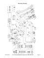
AIR FLOOR JACK
25 TON / 50 TON
Model 92840
ASSEMBLY and OPERATING
INSTRUCTIONS
®
3491 Mission Oaks Blvd., Camarillo, CA 93011
Visit our Web site at http://www.harborfreight.com
TO PREVENT SERIOUS INJURY OR DEATH,
READ AND UNDERSTAND ALL WARNINGS
AND INSTRUCTIONS BEFORE USE.
Copyright© 2005 by Harbor Freight Tools®. All rights reserved. No portion of this
manual or any artwork contained herein may be reproduced in any shape or form
without the express written consent of Harbor Freight Tools.
For technical questions and replacement parts, please call 1-800-444-3353
Specifications
Lift Capacity
Lifting Range
Air Inlet
Maximum Air Pressure
Minimum Air Pressure
Air Requirements
Overall Dimensions
Ram (2) Diameter
Weight
25 Tons (Stage 2) to 50 Tons (Stage 1)
8-5/8” to 13-1/4” (Stage 1)
13-1/4” to 19-1/8” (Stage 2)
1/4”-18 NPT
200 PSI
150 PSI
9.5 CFM
40” L x 10-1/2” W x 60-1/4”
2-3/4”
174 Lbs.
Save This Manual
You will need the manual for the safety warnings and precautions, assembly instructions,
operating and maintenance procedures, parts list and diagram. Keep your invoice with this
manual. Write the invoice number on the inside of the front cover. Keep the manual and
invoice in a safe and dry place for future reference.
Safety Warnings and Precautions
WARNING: When using tool, basic safety precautions should always be followed to
reduce the risk of personal injury and damage to equipment.
Read all instructions before using this tool!
1.
Keep work area clean. Cluttered areas invite injuries.
2.
Observe work area conditions. Do not use machines or equipment in damp or wet
locations. Don’t expose to rain. Keep work area well lit. Do not use electrically
powered compressors in the presence of flammable gases or liquids.
3.
Keep children away. Children must never be allowed in the work area. Do not let
them handle machines, tools, extension cords, or air hoses.
4.
Store idle equipment. When not in use, tools must be stored in a dry location to
inhibit rust. Always lock up tools and keep out of reach of children.
5.
Use the right tool for the job. Do not attempt to force a small tool or attachment to
do the work of a larger industrial tool. There are certain applications for which this tool
was designed. It will do the job better and more safely at the rate for which it was
intended. Do not modify this tool and do not use this tool for a purpose for which it
was not intended.
6.
Dress properly. Do not wear loose clothing or jewelry as they can be caught in
moving parts. Protective, electrically non-conductive clothes and non-skid footwear
are recommended when working. Wear restrictive hair covering to contain long hair.
7.
Use eye protection. Always wear ANSI approved impact safety goggles. Wear
heavy work gloves.
SKU 92840
For technical questions, please call 1-800-444-3353
Page 2
8.
Do not overreach. Keep proper footing and balance at all times. Do not reach over or
across Jack or Jack Stands under a load.
9.
Maintain tools with care. Keep tools clean for better and safer performance. Follow
instructions for lubricating and changing accessories. Inspect tool cords and air hoses
periodically and, if damaged, have them repaired by an authorized technician. The
handle must be kept clean, dry, and free from oil and grease at all times.
10.
Disconnect air supply. Disconnect air hose when not in use.
11.
Avoid unintentional starting. Be sure the controls are in the neutral position when
not in use and before plugging in. Do not move any tool while touching the controls,
whether it is connected to the air or not.
12.
Stay alert. Watch what you are doing, use common sense. Do not operate any tool
when you are tired.
13.
Check for damaged parts. Before using any tool, any part that appears damaged
should be carefully checked to determine that it will operate properly and perform its
intended function. Check for alignment and binding of moving parts; any broken parts
or mounting fixtures; and any other condition that may affect proper operation. Any
part that is damaged should be properly repaired or replaced by a qualified technician.
Do not use the tool if the controls do not operate properly.
14.
Guard against electric shock. Prevent body contact with grounded surfaces such as
pipes, radiators, ranges, and refrigerator enclosures.
15.
Replacement parts and accessories. When servicing, use only identical
replacement parts. Use of any other parts will void the warranty. Only use accessories
intended for use with this tool. Approved accessories are available from Harbor Freight
Tools.
16.
Do not operate tool if under the influence of alcohol or drugs. Read warning
labels if taking prescription medicine to determine if your judgement or reflexes are
impaired while taking drugs. If there is any doubt, do not operate the tool.
17.
Use proper size and type extension cord. If an extension cord is required for the air
compressor, it must be of the proper size and type to supply the correct current to the
compressor without heating up. Otherwise, the extension cord could melt and catch
fire, or cause electrical damage to the compressor. Check your air compressor’s
manual for the appropriate size cord.
18.
Maintenance. For your safety, maintenance should be performed regularly by a
qualified technician.
19.
Compressed air only. Never use combustible gas as a power source.
Note: Performance of the compressor (if powered by line voltage) may vary depending on
variations in local line voltage. Extension cord usage may also affect tool performance.
Warning: The warnings, cautions, and instructions discussed in this instruction manual
cannot cover all possible conditions and situations that may occur. It must be understood by the operator that common sense and caution are factors which cannot be
built into this product, but must be supplied by the operator.
SKU 92840
For technical questions, please call 1-800-444-3353
Page 3
Specific Jack Safety Instructions
Warning!! Stand clear of the Jack when raising or lowering a vehicle.
1.
Jack Capacity. Never exceed the Jack’s capacity of 25 Tons (Stage 2) or 50 Tons
(Stage 1). Check the vehicle’s owner’s manual to determine the actual gross weight of
your vehicle before attempting to lift it. Never attempt to lift a load greater than 25 Tons
above the Stage 1 level.
2.
Never ride on the Jack. Never ride on the Jack, and never have people or pets in the
vehicle you are raising.
3.
Only use Jack to raise/lower vehicle. After raising the vehicle, use jack stands to keep
the vehicle suspended for any period of time. Do not work on, around, or under the
vehicle while it is supported by the Jack.
4.
Place Jack on correct surface. Only use this Jack on a stable, smooth, level,
clean, and dry surface that is capable of sustaining the load (ie. thick cured concrete
or thick steel). This Jack has exposed hoses in its undercarriage.
5.
Stabilize the load. Ensure that the load remains stable at all times.
6.
Vehicle lifting. When lifting a vehicle, apply the emergency brake and block all of the
wheels that will remain on the ground.
7.
Center load. Center the load on the Jack Ram (2). Off-center loads can damage seals,
causing Jack failure.
8.
Lift only using correct vehicle lift points. Read the vehicle manual to find the proper
lifting points for the vehicle.
9.
Never use the Jack unless it is filled with hydraulic fluid. Filling with hydraulic fluid
is covered in the maintenance section of this manual.
10.
NEVER USE THIS JACK FOR AIRCRAFT PURPOSES.
11.
Industrial applications must follow OSHA requirements.
12.
Never move jack when under load. The wheels are intended for NO LOAD movement
only.
Unpacking
When unpacking, check to make sure that the product is intact and undamaged. If any parts
are missing or broken, please call Harbor Freight Tools at the number on the cover of this
manual as soon as possible.
Assembly
Before use, the Shipping Plug (99) must be removed and replaced with the Oil Plug (26).
The Oil Plug (26) is hanging from the Shipping Plug. Changing these plugs must be done
prior to running the unit. See FIGURE 4 under Maintenance, on page 7. Save the Shipping
Plug (99) for any further transport.
SKU 92840
For technical questions, please call 1-800-444-3353
Page 4
Air Connection
Two Stage
Jack
For best service you should incorporate an oiler, regulator, and inline filter, as shown in the
diagram above. Hoses, couplers, oilers, regulators, and filters are all available at Harbor
Freight Tools.
1.
You will need to prepare a 1/4” air connector (not included) to connect to the Air Inlet
(29) on the Handle (40) of the Jack. First, wrap the 1/4” air connector with pipe thread
seal tape before threading it into the Air Inlet (29). Connect the 3/8” ID air source hose
to a quick connect coupler, and then to the Impact Wrench. See FIGURE 1.
Note: If you are not using an automatic oiler system, before operation, add a few drops
of Pneumatic Tool Oil to the airline connection. Add a few drops more after each hour
of continual use.
2.
Set the air pressure on the regulator to 150-200 PSI. Do not exceed the recommended air pressure of 200 PSI.
3.
Check the air connection for leaks. Disconnect from the air source.
FIGURE 1
Lever (27)
Air Inlet (29)
Controls
Explanation
Handle (40)
Handle Position Lever
SKU 92840
For technical questions, please call 1-800-444-3353
Page 5
Operation
Raising the Vehicle
Note: This Two Stage Jack comes with two Adapters (1). The two Adapters (1) are stored by
the wheels of the Jack (see FIGURES 2 and 3).
FIGURE 2
Both Adapter (1) extensions on.
Note: The Handle is adjustable. You can position it into any of the slots shown in FIGURE 3
below by pulling the Handle Position Lever, and moving the Handle until the lever drops
into place (see FIGURE 1 on page 5).
FIGURE 3
Adapter (1)
Adapter (1)
Warning! The Jack and vehicle being lifted must be stable when lifted so they do not
fall and cause personal injury. Keep spectators away from the work area. Read
the vehicle manual to find the proper lifting points for the vehicle.
1.
Position the Jack under the vehicle to be lifted is at one of the recommended lifting
points. Connect to the air source and turn on the compressor. Turn the Lever (27) to
the right toward the UP arrow on the Controls (see FIGURE 1 on page 5). Lift the load
slightly and check that the load is stable on the jack. If not, lower the load and check
that the vehicle has no load on it and that the jack is in the proper position. Allow the
Jack to rise to the desired level, and then move the Lever (27) into the neutral position
between the UP and DOWN positions (shown in FIGURE 1).
2.
Place jack stands (not included) under the vehicle before attempting to do any
work on, in, under, or around the vehicle.
SKU 92840
For technical questions, please call 1-800-444-3353
Page 6
Operation (continued)
Lowering the Vehicle
1.
First, clear any tools or equipment from under the vehicle. Make sure there are no
obstructions and that people are at a safe distance from the vehicle.
Note: Position yourself safely so that your body is not under any part of the
vehicle before lowering the Jack or removing the jack stands.
2.
Position the Jack so that the Ram (2) is at one of the recommended lifting points.
Turn the Lever (27) to the right toward the UP arrow on the Controls (see FIGURE 1 on
page 5). Raise the Jack just enough so that you can remove the jack stands. Then,
turn back the Lever (27) to the neutral position and remove the jack stands.
3.
Lower the load slowly in a controlled fashion: Turn the Lever (27) slightly to the left
toward the DOWN arrow on the Controls (see FIGURE 1 on page 5), and allow the load
to lower slowly.
4.
Remove the Jack from under the vehicle. Disconnect the air supply.
Maintenance
1.
Keep the Jack clean and dry. When not in use, store in a dry location to inhibit rust.
Always lock up equipment and keep out of reach of children.
2.
Have a qualified service technician periodically dismantle and lubricate the handle
assembly and all lift arm linkages.
3.
Before each use, check the oil level through the oil plug hole shown in FIGURE 4 below.
Make sure it is full before each use. Fill oil if necessary by removing the Oil Plug (26).
Watch for hydraulic oil leaks. If leaks are present, contact a qualified service technician. Have a qualified service technician change the oil and lubricate the Jack annually.
FIGURE 4
Replace Shipping Plug (99)
with Oil Plug (26)
SKU 92840
For technical questions, please call 1-800-444-3353
Page 7
Parts List
Part No.
1
2
3
4
5
6
7
8
9
10
11
12
13
14
15
16
17
18
19
20
21
22
23
24
25
26
27
28
29
30
31
32
33
34
Description
Adapter
Ram
Dust Ring
0-ring
Piston Rod
0-ring
y-ring
Bushing
Sp. Washer
Plate
0-ring
Ring
0-ring
y-ring
Ring
0-ring
Bushing
Union
Hand Ring
Ring
Screw
Wheel
Sp. Washer
Rod
Sp. Washer
Oil Plug
Lever
Ring
Air Inlet
Sp. Base
Valve Block
0-ring
Valve Body
Union
Qty.
2
1
1
1
1
1
1
1
1
1
1
1
1
1
1
1
1
1
1
2
2
2
2
1
2
1
1
1
1
1
1
1
1
2
Part No.
35
36
37
38
39
40
41
42
43
44
45
46
47
48
49
50
51
52
53
54
55
56
57
58
59
60
61
62
63
64
65
66
67
68
Description
Rod
Pin
0-ring
Bolt
Spring Washer
Handle
Bolt
Union
Ring
Tube
Union
Screw
Bolt
Switch Case
0-ring
Union
Tube
Air Pipe Assy.
Union
Tube
Union
Oil Box
Bolt
Sp. Washer
Union
0-ring
Cover
Spring
Rel. Rod
Spring
Bearing
Sp. Seat
Spring
Screw
Qty.
1
1
3
2
4
1
2
1
4
2
1
1
4
1
2
1
1
1
1
1
2
1
4
2
1
5
1
1
1
4
5
1
1
1
Part No.
69
70
71
72
73
74
75
76
77
78
79
80
81
82
83
84
85
86
87
88
89
90
91
92
93
94
95
96
97
98
99
100
Description
Washer
Screw
Spring
Spring
Spring
0-ring
Union
Box
Spg. Washer
Bolt
Bolt
Spg. Washer
Valve Base
0-ring
Bushing
Ring
y-ring
Bolt
Piston Rod
Plate
Big Piston
Pro. Ring
0-ring
Pump Body
Bushing
Seal Washer
Small Piston
Cover
Ball
Cyl. Base
Ship. Plug
0-ring
Qty.
5
5
1
1
1
1
1
1
4
4
1
1
1
2
1
1
1
1
1
1
1
1
1
1
1
1
1
1
1
1
1
1
PLEASE READ THE FOLLOWING CAREFULLY
THE MANUFACTURER AND/OR DISTRIBUTOR HAS PROVIDED THE PARTS DIAGRAM IN THIS
MANUAL AS A REFERENCE TOOL ONLY. NEITHER THE MANUFACTURER NOR DISTRIBUTOR MAKES ANY REPRESENTATION OR WARRANTY OF ANY KIND TO THE BUYER THAT HE
OR SHE IS QUALIFIED TO MAKE ANY REPAIRS TO THE PRODUCT OR THAT HE OR SHE IS
QUALIFIED TO REPLACE ANY PARTS OF THE PRODUCT. IN FACT, THE MANUFACTURER
AND/OR DISTRIBUTOR EXPRESSLY STATES THAT ALL REPAIRS AND PARTS REPLACEMENTS
SHOULD BE UNDERTAKEN BY CERTIFIED AND LICENSED TECHNICIANS AND NOT BY THE
BUYER. THE BUYER ASSUMES ALL RISK AND LIABILITY ARISING OUT OF HIS OR HER
REPAIRS TO THE ORIGINAL PRODUCT OR REPLACEMENT PARTS THERETO, OR ARISING
OUT OF HIS OR HER INSTALLATION OF REPLACEMENT PARTS THERETO.
NOTE: Some parts are listed and shown for illustration purposes only and are not available
individually as replacement parts.
SKU 92840
For technical questions, please call 1-800-444-3353
Page 8
Assembly Drawing
SKU 92840
For technical questions, please call 1-800-444-3353
Page 9