1
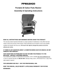
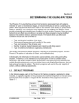
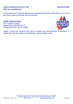
MOUNTABLE WALL SINK
90326
ASSEMBLY AND OPERATING INSTRUCTIONS
3491 Mission Oaks Blvd., Camarillo, CA 93011
Visit our Web site at http://www.harborfreight.com
Copyright © 2003 by Harbor Freight Tools®. All rights reserved. No portion of
this manual or any artwork contained herein may be reproduced in any shape
or form without the express written consent of Harbor Freight Tools.
For technical questions and replacement parts, please call 1-800-444-3353
Specifications
Overall Dimensions
Sink Capacity
Spout
Weight
Hose Fitting
34-1/4” W x 17-/58” Deep x 17” H
10.5 Gallons
10” H - 8” Overhang
11.2 Lbs.
3/4”
Save This Manual
You will need the manual for the safety warnings and precautions, assembly instructions,
operating and maintenance procedures, parts list and diagram. Keep your invoice with this
manual. Write the invoice number on the inside of the front cover. Keep the manual and
invoice in a safe and dry place for future reference.
Safety Warnings and Precautions
WARNING: When using product, basic safety precautions should always be followed
to reduce the risk of personal injury and damage to equipment.
Read all instructions before using this product!
1.
Keep work area clean. Cluttered areas invite injuries.
2.
Observe work area conditions. Keep work area well lighted.
3.
Keep children away. Children must never be allowed in the work area during
assembly. Do not let them play in the sink as it will not support their weight.
4.
Store idle equipment. Always keep sink accessories out of reach of children.
5.
Use the right tool for the job. Do not attempt to force a small product or attachment
to do the work of a larger industrial product. There are certain applications for which
this product was designed. It will do the job better and more safely at the rate for
which it was intended. Do not modify this product and do not use this product for a
purpose for which it was not intended.
6.
Dress properly. Do not wear loose clothing or jewelry as they can be caught in
moving parts. Protective, electrically non-conductive clothes and non-skid footwear
are recommended when working. Wear restrictive hair covering to contain long hair.
7.
Use eye protection. Always wear ANSI approved impact safety goggles during
assembly.
8.
Do not overreach. Keep proper footing and balance at all times.
9.
Maintain tools with care. Keep the sink and fixtures clean for better and safer
performance. Follow instructions for changing accessories. Inspect hoses periodically,
and if damaged, have them repaired by an authorized technician. The handles must
be kept clean, dry, and free from oil and grease at all times.
SKU 90326
Page 2
10.
Stay alert. Watch what you are doing, use common sense. Do not operate or
assemble the Sink when you are tired.
11.
Check for damaged parts. Before using any product, any part that appears
damaged should be carefully checked to determine that it will operate properly and
perform its intended function. Check for alignment and binding of moving parts; any
broken parts or mounting fixtures; and any other condition that may affect proper
operation. Any part that is damaged should be properly repaired or replaced by a
qualified technician.
12.
Replacement parts and accessories. When servicing, use only identical
replacement parts. Use of any other parts will void the warranty. Only use accessories
intended for use with this product. Approved accessories are available from Harbor
Freight Tools.
13.
Do not operate the Sink if under the influence of alcohol or drugs. Read warning
labels if taking prescription medicine to determine if your judgment or reflexes are
impaired while taking drugs. If there is any doubt, do not operate the product.
14.
Maintenance. For your safety, service and maintenance should be performed
regularly by a qualified technician.
Warning: The chrome covered copper tubing on the Faucet (Spout (#6)) is very delicate and
should be handled with care. Do not lift or pull on the Faucet (Spout (#6)).
Warning: The warnings, cautions, and instructions discussed in this instruction manual
cannot cover all possible conditions and situations that may occur. It must be understood by the operator that common sense and caution are factors which cannot be
built into this product, but must be supplied by the operator.
Unpacking
When unpacking, check to make sure the parts listed on page 7 are included. If any parts
are missing or broken, please call Harbor Freight Tools at the number on the cover of this
manual as soon as possible.
WARNING: The brass components of this product contain lead, a chemical known to the
State of California to cause birth defects (or other reproductive harm). (California Health &
Safety code 25249.5, et seq.)
SKU 90326
Page 3
Assembly
FIGURE 1
(Overall view)
FIGURE 2
Upper Drain
Connection
Pin Holes
Water Inlet
(Attach 3/4” Hose)
(not included)
Pipe (#8)
Water Outlet
(Attach 3/4” Hose)
(not included)
Elbow (#9)
Elbow (#9) connects to
Drain Set (#11)
SKU 90326
Page 4
Assembly (continued)
Note: When deciding where to mount the
sink, make sure the wall can handle the
weight of the sink and at least the weight of
10.5 gallons of water (8 Lbs. per gallon). We
recommend mounting into wall studs. Plan
the Sink to be located near the water source.
FIGURE 3
Refer to FIGURES 1,2,3,4,5.
1. Attach the two Wall Supports (#3) to the
Sink by meshing together the Pins on the
Wall Supports (#3) next to the Pin Holes on
underside of each side of the Sink.See
FIGURE 2. Once the Sink is fully attached
to the Wall Supports (#3), fit the four
Mounting Brackets (#1) onto the
Rectangular Support Ends on each Wall Support (#3). The Mounting Brackets (#1) will
fit into the gap between the Rectangular Support End and the vertical bar of the Wall
Support (#3). Hold the Sink, with the
FIGURE 4
Rectangular
supports and brackets, up against the
Support Ends
wall. Use a level to make sure the Sink
is perpendicular to the ground, and mark
where each screw hole on the
Mounting Brackets (#1) should go.
After marking your mounting spots,
detach the Sink from the
Wall Supports (#3), and remove the
Mounting Brackets (#1) from the
Wall Supports (#3)
Wall Supports (#3).
Mounting Bracket (#1)
2. Screw the Mounting Brackets (#1) to
the wall (screws not included). See
FIGURE 3.
FIGURE 5
3. Fit the four Rectangular Support
Ends on each Wall Support (#3) into
the gap between the Rectangular
Support End and the vertical bar of the Wall
Support (#3). See FIGURE 4.
Pins
4. Fit the three Pins on each Wall
Support (#3) to the Sink by meshing
together the Pins on the Wall
Supports (#3) with the corresponding
Pin Holes on underside of each side of
the Sink.
SKU 90326
Page 5
Assembly (continued)
5. To install the Drain Set (#11):Set the Drain
Ring into the hole in the Sink. Hold the
Gasket and the Funnel under the Sink in
positionunder the hole. Attach them with the
screw. See FIGURES 2 and 6.
6. Attach the Elbow (#9) to the Funnel with
the Connector (#10). See FIGURE 6.
7. Attach the Pipe (#8) into the Elbow (#9)
in the bottom, and the piece of pipe coming
from the upper drain on the top.
See FIGURES 2 and 6.
FIGURE 6
Screw
Drain Ring
Gasket
Funnel
FIGURE 7
8. Set the Spout (#6) into the hole next
to the upper drain and connect it under
the Sink with the Spout Connector (#6).
Attach the Intake Coupler (#12) to the
Spout Connector (#6).
9. Attach a 3/4” hose (not included) to the
threaded Water Inlet. See FIGURE 2.
Attach a 3/4” hose using hose clamps
(not included) to the Water Outlet. Route
hose to your planned location for waste
water exit.
10. Check the Sink and all the fittings for
leaks and that it properly drains. Once
you’re sure that everything is satisfactory,
the Sink is ready for use.
FIGURE 8
Note: The small tray and the washboard
tray easily set in the top of the Sink when
needed. See the cover photo.
Maintenance
1. Periodically check that all of the
connections are tight.
2. Keep the drain clear of all obstructions.
SKU 90326
Page 6
Parts List and Assembly Drawing
1
7
8
2
Part No.
1
2
3
4
5
6
7
8
9
10
11
12
Description
Mounting Bracket
Sink
Wall Support
Washboard
Tray
Spout/Spout Connector
Hose Coupler
Pipe
Elbow
Connector
Drain Set
Inlet Coupler
Qty.
4
1
2
1
1
1 each
1
1
1
1
1
1
9
3
10
11
4
5
6
12
6
PLEASE READ THE FOLLOWING CAREFULLY
THE MANUFACTURER AND/OR DISTRIBUTOR HAS PROVIDED THE PARTS DIAGRAM IN THIS
MANUAL AS A REFERENCE TOOL ONLY. NEITHER THE MANUFACTURER NOR DISTRIBUTOR MAKES ANY REPRESENTATION OR WARRANTY OF ANY KIND TO THE BUYER THAT HE
OR SHE IS QUALIFIED TO MAKE ANY REPAIRS TO THE PRODUCT OR THAT HE OR SHE IS
QUALIFIED TO REPLACE ANY PARTS OF THE PRODUCT. IN FACT, THE MANUFACTURER
AND/OR DISTRIBUTOR EXPRESSLY STATES THAT ALL REPAIRS AND PARTS REPLACEMENTS
SHOULD BE UNDERTAKEN BY CERTIFIED AND LICENSED TECHNICIANS AND NOT BY THE
BUYER. THE BUYER ASSUMES ALL RISK AND LIABILITY ARISING OUT OF HIS OR HER
REPAIRS TO THE ORIGINAL PRODUCT OR REPLACEMENT PARTS THERETO, OR ARISING
OUT OF HIS OR HER INSTALLATION OF REPLACEMENT PARTS THERETO.
NOTE: Some parts are listed and shown for illustration purposes only and are not available
individually as replacement parts.
SKU 90326
Page 7