1
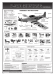
Heavy Duty
French Fry
Cutter
66473
Instructions and precautions
Visit our website at: http://www.harborfreight.com
Save these instructions. Read all
precautions and instructions.
Copyright© 2009 by Harbor Freight Tools®. All rights reserved. No portion of this document or any artwork contained
herein may be reproduced in any shape or form without the express written consent of Harbor Freight Tools. Diagrams
within this document may not be drawn proportionally. Due to continuing improvements, actual product may differ
slightly from the product described herein. Tools required for assembly and service may not be included.
For technical questions or replacement parts, please call 1-800-444-3353.
Specifications
Two sizes of Cutters and Pushing Blocks are
included in this set. This tool may be wall or table
top mounted. This tool may be disassembled for
cleaning.
missing or broken, please call Harbor Freight Tools
at the number shown on the cover of this document
as soon as possible.
Important SAFETY
Information
Cutter Frame Size: 4-5/8”W x 4-5/8”H x 11/16”T
Unpacking
When unpacking, check to make sure that
the item is intact and undamaged. If any parts are
Revised Manual 09j
1.
This is a cutting device. Do not place hand
near Pushing Block and Cutter.
2.
Do not hold vegetable or any object in place
during cutting operation.
3.
To prevent pinch injury, keep hands clear of
Lever (1) and Push Rods (9) at all times.
4.
Assemble and use according to these
instructions only. Improper assembly or use
can create hazards.
5.
Wear ANSI-approved safety goggles and
heavy-duty work gloves during assembly.
6.
Keep assembly and use area clean and well lit.
7.
Keep bystanders out of the area during
assembly and use.
8.
Do not assemble or use when tired or when
under the influence of drugs or medication.
9.
This product is not a toy. Do not allow
children to play with or near this item.
10.
Use for intended purpose(s) only.
11.
Inspect before use; do not use if parts are
loose or damaged.
12.
Maintain product labels and nameplates.
These carry important safety information.
If unreadable or missing, contact Harbor
Freight Tools for a replacement.
Foodborne Illness Safety
1.
Before every use, thoroughly clean the
appliance (see “Cleaning” section for
instructions) and wash your hands.
2.
Follow Food and Drug Administration (FDA)
food safety recommendations for cooking
and food handling (www.fda.gov). Also, refer
to the following safety information, taken from
FDA’s website:
a. Keep hot food hot (above 140° F) and
cold food cold (below 40° F). Do not let
perishable food sit out longer than 2 hours
(1 hour in temperatures above 90° F).
Read the entire Important
Safety Information section
at the beginning of this document
including all text under subheadings
therein before set up or use of this
product.
Assembly
1.
Position the Cutting Frame (10 or 12) against
the End Support (2).
2.
Insert the longer threaded end of each of
the three Support Rods (7) into the openings
of the End Support (2) and Cutting Frame.
Secure in place using three Wing Nuts (15).
3.
Insert the Cutting Frame Bolt (16) into the
opening at the top of the End Support (2) and
Cutting Frame (10 or 12). Secure using one
of the Wing Nuts (19).
4.
Place the Food Tray (6) in position.
5.
Place Lever Support (3) onto the ends of the
Support Rods (7) and fix in place using Wing
Nuts (15).
6.
Place appropriate sized Push Block (11 or
13) on the Block Plate A (4) and fix in place
by turning the Toggles.
7.
Attach the Lever Assembly (1 and 8) to the
Lever Support (3) using the Axle Bolt and Nut
(17). Tighten the Nut still allowing the Lever
to move freely.
8.
Attach the Push Rods (9) to the Lever (1)
using the Push Rod Bolt and Nut (18).
Tighten the Nut still allowing the Lever to
move freely.
Mounting the Tool
1.
The tool is to be mounted to a wall or table.
2.
The mounting surface must be flat or level
and sturdy enough to support the weight
of the tool, products placed on the tool and
forces exerted when using the tool.
3.
Remove the Lever Support (3).
4.
Hold the tool in position and mark the four
mounting hole positions. Set the tool aside.
5.
Check to be sure that you will not drill into
any concealed wires, pipes, hoses or ducts
at the points marked. Drill holes at each of
the four marked points.
6.
Reposition the tool and attach it using
suitable fasteners (not included).
Changing Push Block
and Cutting Frame
1.
This item is supplied with two sets of Cutting
Frames and Push Blocks for making different
sized french fries.
2.
To change size of french fry produced,
change Push Blocks and Cutting Frames.
3.
To remove Push Block (11 or 13), rotate the
two swivel latches outward. The Block can be
lifted out.
REV 09c; 09j
SKU 66473
For technical questions, please call 1-800-444-3353.
Page 2
Block and Cutting Frame will damage the
tool.
Operation
1.
Pull the Lever (1) back, which will pull the
Push Block back from the Cutting Frame.
2.
Place a bowl beneath the End Support (2)
to catch the cut french fries as they are
produced.
3.
Place the potato or vegetable to be cut in the
Food Tray (6). Align the vegetable roughly
with the center of the Cutting Frame.
4.
Press the Lever (1) forward. The Push Block
will press the vegetable through the Cutting
Frame. Stop pressing the Lever forward once
the vegetable has been cut.
Push Block Latches
4.
To remove the Cutting Frame (10 or 12),
remove the four wing nuts holding it in place.
WARNING: Handle the Cutting Frame by the
outer edge only. The blades are sharp and
can cause injury if handled. The blades are
not removable from the Cutting Frame.
Cleaning
1.
Remove both the Cutting Frame (10 or 12)
and Push Block (11 or 13).
5.
To replace the Push Block, place it against
Block Plate A (4) with hooks protruding
through holes in Block Plate A. Then fix it in
place with the two swivel latches.
2.
Lift Food Tray (6) out of tool.
3.
Wash Cutting Frame, Push Block and Food
Tray in dishwasher, or by hand using hot
water and detergent.
6.
To replace the Cutting Frame, position it on
the end of the End Support (2) and attach it
with the Wing Nuts.
4.
Wipe off the rest of the tool using a clean
damp cloth with light detergent. Wipe it dry
after cleaning.
Wing Nut (19)
Wing Nuts(15)
NOTE: Always use the Push Blocks and Cutting
Frames in matched pairs. Using mismatched
SKU 66473
For technical questions, please call 1-800-444-3353.
Page 3
1
Record Serial Number Here:
8
11
16
10
19
7
2
4
Note:If product has no serial number, record
month and year of purchase instead.
5
3
Note:Some parts are listed and shown for
illustration purposes only, and are not
available individually as replacement parts.
9
6
18
17
15
Parts List & assembly
diagram
Part
Description
Qty.
1
Lever
1
2
End Support (Stand A)
1
3
Lever Support (Stand B)
1
4
Block Plate A
1
5
Block Plate B
1
6
Food Tray
1
7
Support Rods with Wing Nuts
D12 x L27.4 cm
3
8
Lever Rods D7 x L37 cm
2
9
Push Rods D7 x L22 cm
2
10
Cutting Frame 64 Holes
1
11
Push Block 64 Holes
1
12
Cutting Frame 36 Holes(not shown)
1
13
Push Block 36 Holes(not shown)
1
15
Wing Nuts 5/16”
3
16
Cutting Frame Bolt
1
17
Axle Bolt and Nut set
1
18
Push Rod Bolt and Nut set
1
19
Wing Nut M5
1
PLEASE READ THE FOLLOWING
CAREFULLY
The manufacturer and/or distributor has
provided the parts list and assembly diagram in
this document as a reference tool only. Neither
the manufacturer or distributor makes any
representation or warranty of any kind to the
buyer that he or she is qualified to make any
repairs to the product, or that he or she is
qualified to replace any parts of the product.
In fact, the manufacturer and/or distributor
expressly states that all repairs and parts
replacements should be undertaken by certified
and licensed technicians, and not by the buyer.
The buyer assumes all risk and liability arising
out of his or her repairs to the original product
or replacement parts thereto, or arising out
of his or her installation of replacement parts
thereto.
REV 09c, 09h, 09j
SKU 66473
For technical questions, please call 1-800-444-3353.
Page 4